
Service Repair Manual Models 924G and 924Gz Wheel Loader
Shutdown SIS Previous Screen Product: WHEEL LOADER Model: 924G WHEEL LOADER AAN Configuration: 924G and 924Gz Wheel Loader AAN00001-UP (MACHINE) POWERED BY 3056 Engine Disassembly and Assembly 924G and 924GZ Wheel Loaders Power Train Media Number -RENR3506-05 Publication Date -01/05/2004 Date Updated -09/10/2017 i02055589 Power Shift Transmission - Assemble SMCS - 3030-016 Assembly Procedure Table 1 Required Tools Tool Part Number Part Description Qty A 1P-2420 Transmission Repair Stand 1 B 1U-9759 Jack Stand 1 C 6V-2156 Link Bracket 2 D 4C-6136 Lifting Bracket 1 E 4C-6399 Spring Compressor 1 F FT-2343 Plexiglass Cover 1 G 4C-6143 Clutch Piston Installer 1 H 4C-3652 Spring Compressor 1 J 4C-6137 Bearing Installer 1 4C-6142 Spacer 1 1P-531 Handle 1 K 4C-6402 Plug Installer 1 L 5P-3413 Pipe Sealant 1 M 9S-3263 Thread Lock Compound 1 N 1U-8846 Gasket Sealant 1

Note: Cleanliness is an important factor. Before assembly, all parts should be thoroughly cleaned in cleaning fluid. Allow the parts to air dry. Wiping cloths or rags should not be used to dry parts Lint may be deposited on the parts which may cause later trouble. Inspect all parts. If any parts are worn or damaged, use new parts for replacement. Illustration 1 g00655451 1. Install gear (152) and ring (151). Heat bearing (150) to a temperature of 135 °C (275 °F). Install bearing (150). Illustration 2 g00655464 2. Heat bearing (149) to a temperature of 135 °C (275 °F). Install bearing (149).


Illustration 3 g00890761 3. ApplyTooling (L) to the seal bore. 4. Install lip seal (148). Lubricate the sealing lip with the lubricant that is being used. 5. Lower the temperature of bearing cup (146). Install bearing cup (146). 6. Use bolts (145) in order to install shield assembly (147). The torque for bolts (145) is 55 ± 10 N·m (40 ± 10 lb ft). Illustration 4 g00655439 7. Install the output shaft and gear (144). Illustration 5 g00890760 8. Use nuts (142) in order to install cover (143). The torque for nuts (142) is 9 ± 1 N·m (6 ± 1 lb ft).


Illustration 6 g00890759 9. Install lip type seal (141). Lubricate the sealing lip with the lubricant that is being used. 10. Lower the temperature of bearing cup (140). Install bearing cup (140). 11. Install seal (139). Illustration 7 g00655206 12. Install shims (138). Use the shims in order to get 0.06 mm (0.002 inch) to 0.13 mm (0.005 inch) end play on the output shaft. Note: Lubricate the bore of the housing with the lubricant that is being used.


Illustration 8 g00655180 13. Use bolts (135) in order to install the cage. The torque for bolts (135) is 70 ± 10 N·m (50 ± 10 lb ft). Illustration 9 g00890758 14. Install parking brake assembly (133) and lever (134). 15. Use bolts (131) in order to install plate (132). The torque for bolts (131) is 120 ± 20 N·m (90 ± 15 lb ft). Illustration 10 g00890622 16. Install brake drum (130) and yoke (129) together. Install seal (128).


Illustration 11 g00685060 17. Install the bolt and washer (127). The torque for bolt (127) is 120 ± 20 N·m (90 ± 15 lb ft). Illustration 12 g00655120 18. Use washer (125), and bolt (124) in order to install yoke (126) . The torque for bolt (124) is 120 ± 20 N·m (90 ± 15 lb ft). Illustration 13 g00655110 19. Lower the temperature of bearing cups (123). Install bearing cups (123). Use Tooling (J) to install bearing (122).


Illustration 14 g00890621 20. Install gear (119). Heat bearing (118) to a temperature of 135 °C (275 °F). Install bearing (118). 21. Install gear (120). Heat bearing (121) to a temperature of 135 °C (275 °F). Install bearing (121). 22. Install seal (116) on carrier (117), and install carrier (117). Illustration 15 g00655016 23. Install the input shaft assembly (115). Illustration 16 g00654969


24. Install seals (112), (113), and (114). Illustration 17 g00654966 Note: Lubricate the piston, and the bore with clean transmission oil. 25. Use Tooling (G) in order to install piston (111). Illustration 18 g00654842 26. Install spring (110). Illustration 19 g00654837


27. Install the retainer and seal assembly (109). Illustration 20 g00654833 28. Put the clutch pack in a suitable press. Use Tooling (H) in order to install ring (108). Illustration 21 g00654824 29. Lower the temperature of bearing assembly (107). Install bearing assembly (107). Illustration 22 g00654818 30. Install ring (106).
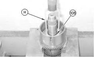


Illustration 23 g00890619 Note: Refer to Specifications, SENR3504, "Power Shift Transmission" for the specifications of the clutch discs. 31. Install plates and discs (105). Install ring (103). Install washers (104) and (102). Illustration 24 g00654724 32. Install hub assembly (101). Illustration 25 g00654719 33. Install gear (100) and ring (99). Install washer (98).


Illustration 26 g00656434 34. Install gear (95) and washer (96). Heat bearing (97) to a temperature of 135 °C (275 °F). Install bearing (97). Note: This completes the assembly of the first gear clutch pack. Note: Refer to Specifications, SENR3504, "Power Shift Transmission" for the procedure to measure running clearance. Illustration 27 g00654638 35. Install seals (94) and (93).


Illustration 28 g00890838 Note: Lubricate the piston, and the bore with clean transmission oil. 36. Use Tooling (G) in order to install piston (90). 37. Install seals (92) on shaft (91). Illustration 29 g00654534 38. Install spring (89), and retainer (88). Illustration 30 g00654525 39. Put the third gear clutch pack in a suitable press. Use Tooling (H) in order to install ring (87).


Illustration 31 g00654519 Note: Refer to Specifications, SENR3504, "Power Shift Transmission" for the specifications of the clutch discs. 40. Install plates and discs (86). Install ring (85). 41. Install washer (84). Illustration 32 g00654517 42. Use a suitable press in order to install bearing (83). Install ring (82). Illustration 33 g00654512


43. Install hub assembly (81). Illustration 34 g00654507 44. Install gear (80) and ring (79). Illustration 35 g00654497 45. Install washer (78) and ring (77). Note: This completes the assembly of the third gear clutch pack. Note: Refer to Specifications, SENR3504, "Power Shift Transmission" for the procedure to measure running clearance .


Illustration 36 g00654494 46. Use Tooling (D) in order to install third gear clutch pack (76). The weight of the clutch pack is approximately 50 kg (110 lb). Illustration 37 g00890612 Note: Use steps 47 through 50 for the assembly of the clutch of the second gear clutch pack. Use Tooling (E) in step 50 instead of Tooling (H). 47. Install washers (75) and (74). Install spacer (73). 48. Install gear (72), spacer (70), and bearing (71). Illustration 38 g00654403 49. Install seals (69) and (68).


Illustration 39 g00890841 Illustration 40 g00654372 Note: Lubricate the piston and the bore with clean transmission oil. 50. Use Tooling (G) in order to install piston (65). Install seals (66) on shaft (67). Illustration 41 g00654364 51. Install spring (64) and retainer (63).


Illustration 42 g00654360 52. Put the reverse clutch pack in a suitable press. Use Tooling (H) in order to install ring (62). Illustration 43 g00890611 53. Use a suitable press in order to install bearing (61). Install ring (60). Illustration 44 g00890610 Note: Refer to Specifications, SENR3504, "Power Shift Transmission" for the specifications of the clutch discs. 54. Install plates and discs (59). Install ring (57).


55. Install washer (58). Illustration 45 g00654347 56. Install hub assembly (56). Illustration 46 g00654328 57. Install gear (55) and ring (54). Illustration 47 g00654339 58. Install washer (53) and ring (52).


Note: This completes the assembly of the reverse second gear clutch pack. Note: Refer to Specifications, SENR3504, "Power Shift Transmission" for the procedure to measure running clearance. Illustration 48 g00654301 59. Use Tooling (D) in order to install reverse second gear clutch pack (51). The weight of the clutch pack is approximately 32 kg (70 lb). Illustration 49 g00654292 60. Install seals (49) and (50).


Illustration 50 g00654280 Note: Lubricate the piston, and the bore with clean transmission oil. 61. Use Tooling (G) in order to install piston (47). 62. Install spring (46), and retainer (45). Illustration 51 g00654276 63. Put the forward high clutch pack in a suitable press. Use Tooling (H) in order to install ring (44). Illustration 52 g00654274 Note: Refer to Specifications, SENR3504, "Power Shift Transmission" for specifications of the clutch discs. 64. Install plates and discs (43). Install ring (42). Install washer (41).


Illustration 53 g00654263 65. Use a suitable press in order to install bearing (40). Install ring (39). Illustration 54 g00654261 66. Install hub (38). Illustration 55 g00654253 67. Heat gear (37) to a temperature of 135 °C (275 °F). Install gear (37). Install ring (36).


Illustration 56 g00654078 68. Install washer (35) and ring (34). Note: This completes the assembly of the forward high gear clutch pack. Note: Refer to Specifications, SENR3504, "Power Shift Transmission" for the procedure to measure running clearance. Illustration 57 g00654063 69. Install O-ring seals (33). Illustration 58 g00890845


Note: Lubricate the piston, and the bore with clean transmission oil. 70. Use Tooling (G) in order to install piston (31). Install seals (32) on shaft (30). Illustration 59 g00654029 71. Install spring (29) and retainer (28). Illustration 60 g00654018 72. Put the forward low clutch pack in a press. Use Tooling (H) in order to compress the spring. Install ring (27). Illustration 61 g00890608


73. Use a suitable press in order to install bearing (25). Install ring (26) in hub (22). Illustration 62 g00653959 74. Install washer (24). Illustration 63 g00890607 Note: Refer to Specifications, SENR3504, "Power Shift Transmission" for specifications of clutch discs. 75. Install plates and discs (23). Install hub (21). Install ring (22). Illustration 64 g00653932


76. Heat gear (20) to a temperature of 135 °C (275 °F). Install gear (20). Install ring (19). Illustration 65 g00653893 77. Install washer (18) and ring (17). Note: This completes the assembly of the forward low gear clutch pack. Note: Refer to Specifications, SENR3504, "Power Shift Transmission" for the procedure to measure running clearance. Illustration 66 g00653858 78. Use Tooling (D) in order to install the forward low and the forward high clutch pack (15). The weight of the clutch pack is approximately 27 kg (60 lb). Note: Use Tooling (K) in order to install plugs (16).


Illustration 67 g00653848 79. Lower the temperature of bearings and race (14). Use Tooling (J) in order to install bearings and race (14). Illustration 68 g00653825 80. Use bolts (12) in order to install gear (13). The torque for bolts (12) is 12 ± 3 N·m (10 ± 2 lb ft). Illustration 69 g00653808 81. Install gear assembly (10).


82. Install O-ring seals (11). Illustration 70 g00653806 83. Install bolts (9). The torque for bolts (9) is 55 ± 10 N·m (40 ± 10 lb ft). Illustration 71 g00653801 84. Apply Tooling (L) to the seal bore. 85. Install lip type seal (7). Lubricate the sealing lip with the lubricant that is being used. 86. Install seal (8).


87.
Illustration 73 g00671890
Illustration 72 g00653775
Note: Lubricate the bore with the lubricant that is being used. Use bolts (5) in order to install plate (6). The torque for bolts (5) is 55 ± 10 N·m (40 ± 10 lb ft).
89.
Illustration 74
Note: Apply Tooling (M) to the threads of bolts (3). Use bolts (3) in order to install flex plate (4) on torque converter (1). The torque for bolts (151) is 60 ± 7 N·m (45 ± 5 lb ft). g00657224 Clean both mating surfaces of the transmission housing. Apply a continuous bead of Tooling (N) to the mating surface of the transmission housing.
88.


Thank you very much for your reading. Please Click Here. Then Get COMPLETE IfNOTE:MANUAL.NOWAITINGthereisnoresponse to click on the link above, please download the PDF document first and then clickonit. GET MORE OTHER MANUALS https://www.aservicemanualpdf.com/ GET MORE OTHER MANUALS https://www.aservicemanualpdf.com/

Illustration 75 g00653680 90. Use Tooling (C) and a suitable lifting device in order to install the top transmission case. Install bolts (2). The torque for bolts (2) is 55 ± 10 N·m (40 ± 10 lb ft). The weight of the top transmission case is approximately 163 kg (360 lb). Note: Install the selector and pressure control valve. Remove Tooling (F). Refer to Disassembly and Assembly, "Selector And Pressure Control Valve (Transmission)Remove And Install". 91. Install torque converter (1). 92. Remove the transmission from Tooling (A) and (B). The weight of the transmission is approximately 500 kg (1100 lb). End By: a. Connect the engine, and the transmission. Refer to Disassembly and Assembly, RENR3503, "Engine to Torque Converter and Transmission - Connect". Copyright 1993 - 2021 Caterpillar Inc. All Rights Reserved. Private Network For SIS Licensees. Mon Jan 25 22:44:03 UTC+0800 2021

Shutdown SIS Previous Screen Product: WHEEL LOADER Model: 924G WHEEL LOADER AAN Configuration: 924G and 924Gz Wheel Loader AAN00001-UP (MACHINE) POWERED BY 3056 Engine Disassembly and Assembly 924G and 924GZ Wheel Loaders Power Train Media Number -RENR3506-05 Publication Date -01/05/2004 Date Updated -09/10/2017 i01740177 Flow Control Valve - Remove and Install SMCS - 5137-010-T3 Removal Procedure Start By: a. Connect the steering frame lock. Refer to Disassembly and Assembly, "Steering Frame Lock - Separate and TableConnect".1 Required Tools Tool Part Number Part Description Qty A 1P-1853 Retaining Pliers 1 Hot oil and hot components can cause personal injury. Do not allow hot oil or hot components to contact skin. At operating temperature, the engine coolant is hot and under pressure. Steam can cause personal injury. Check the coolant level only after the engine has been stopped and the cooling system pressure cap is cool enough to touch with your bare Removehand. the cooling system pressure cap slowly to relieve pressure.
Cooling system conditioner contains alkali. Avoid contact with the skin and eyes to prevent personal injury. NOTICE Care must be taken to ensure that fluids are contained during performance of inspection, maintenance, testing, adjusting, and repair of the product. Be prepared to collect the fluid with suitable containers before opening any compartment or disassembling any component containing fluids. Refer to Special Publication, NENG2500, "Dealer Service Tool Catalog" for tools and supplies suitable to collect and contain fluids on Cat Disposeproducts.ofallfluids according to local regulations and mandates. 1. Drain the transmission oil. Illustration 1 g00664008 2. Remove hose assembly (1).

