
Previous Screen
Product: WHEEL LOADER
Model: 950H WHEEL LOADER M1G
Configuration: 950H Wheel Loader M1G00001-UP (MACHINE) POWERED BY C7 Engine
Disassembly and Assembly
IT62H Integrated Toolcarrier and 950H and 962H Wheel Loaders Power Train
Torque Converter from Transmission, Output Transfer Gears - Separate
SMCS - 3003-076
Separation Procedure
Start By:
A. Remove the torque converter, the transmission, and the output transfer gears. Refer to Disassembly and Assembly, "Torque Converter, Transmission and Output Transfer GearsRemove".
Note: Cleanliness is an important factor. Before the disassembly procedure, the exterior of the component should be thoroughly cleaned. This will help to prevent dirt from entering the internal mechanism.
NOTICE
Care must be taken to ensure that fluids are contained during performance of inspection, maintenance, testing, adjusting and repair of the product. Be prepared to collect the fluid with suitable containers
before opening any compartment or disassembling any component containing fluids.
Refer to Special Publication, NENG2500, "Caterpillar Tools and Shop Products Guide" for tools and supplies suitable to collect and contain fluids on Caterpillar products.
Dispose of all fluids according to local regulations and mandates.
Illustration 1
1. Disconnect harness assemblies (2) and (5) .
2. Remove tube assembly (4) .
3. Remove bolts (3) and transmission oil pump (1) .
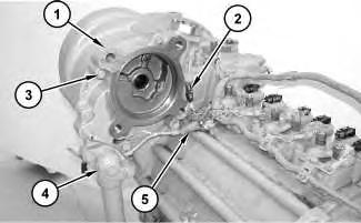
Illustration 2
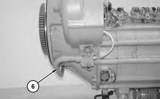
4. Remove tube assembly (6) .
 g01173182
g01173184
g01173182
g01173184


 Illustration 3
7. Reposition torque converter (8), transmission (9), and output transfer gears (10). The combined weight of torque converter (8), transmission (9), and output transfer gears (10) is approximately 816 kg (1800 lb).
8. Remove Tooling (A) .
9. Attach Tooling (B) and a suitable lifting device to torque converter (8). The weight of torque converter (8) is approximately 170 kg (375 lb).
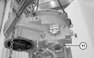
10. Remove bolts (11) .
 Illustration 6
g01173189
Illustration 7
g01173190
Illustration 6
g01173189
Illustration 7
g01173190


Shutdown SIS
Previous Screen
Product: WHEEL LOADER
Model: 950H WHEEL LOADER M1G
Configuration: 950H Wheel Loader M1G00001-UP (MACHINE) POWERED BY C7 Engine
Disassembly and Assembly
IT62H Integrated Toolcarrier and 950H and 962H Wheel Loaders Power Train
Torque Converter (Freewheel Stator) - Disassemble
SMCS - 3101-015
Disassembly Procedure
Table 1
Required Tools
Start By:
A. Separate the torque converter from the transmission and from the output transfer gears. Refer to Disassembly and Assembly, "Torque Converter from Transmission, Output Transfer Gears - Separate".
Note: Cleanliness is an important factor. Before the disassembly procedure, the exterior of the component should be thoroughly cleaned. This will help to prevent dirt from entering the internal mechanism.
1. Remove bolts (2) and transmission hydraulic control relief valve (3) from torque converter housing (1) .


2. Remove torque converter inlet relief valve (4) and the O-ring seal.
 Illustration 1
g01173843
Illustration 2
g01173844
Illustration 3
g01173845
Illustration 1
g01173843
Illustration 2
g01173844
Illustration 3
g01173845
3. Remove bolt (5) and washer (6) .

4. Remove bolts (7) .
5. Remove torque converter speed sensor (8)
6. Remove bolts (9) and pump drive flange (10) .
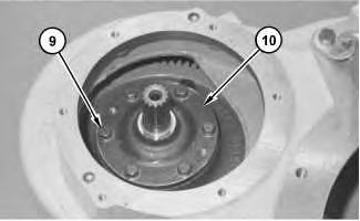 Illustration 4 g01173847
.
Illustration 5 g03835375
Illustration 4 g01173847
.
Illustration 5 g03835375
8. Install Tooling (B) in pump drive gear (13) .


9. Lift pump drive gear (13) and drive gear shaft (12) out of the housing bore.
10. Remove drive gear shaft (12) and bearing (14) from pump drive gear (13) .
11. Use Tooling (A) and a suitable lifting device to remove the torque converter housing assembly. The weight of the torque converter housing assembly is approximately 113 kg (250 lb).
Illustration 6 g01173853 7. Remove bolt (11) from drive gear shaft (12) . Illustration 7 g03835382

 Illustration 8 g01173861
12. Remove drive gear (15) .
Illustration 9 g01173862
13. Remove retaining ring (16) .
14. Use a soft faced hammer in order to free the bearing from the carrier assembly. Remove output shaft (17) from the carrier assembly.
Illustration 8 g01173861
12. Remove drive gear (15) .
Illustration 9 g01173862
13. Remove retaining ring (16) .
14. Use a soft faced hammer in order to free the bearing from the carrier assembly. Remove output shaft (17) from the carrier assembly.
Illustration 10
15. Remove seal ring (18) from output shaft (17) .
16. Use a suitable press to remove bearing (19) .
Illustration 11
17. Remove bolts (20) and impeller (21) .


Illustration 12
18. Reposition impeller (21) .
19. Remove retaining ring (22) and spacer (24) from carrier shaft (23) .
20. Remove stator (25) .
g03835392 g01173864 g0117386621. Remove retaining ring (26) and washer (27) from stator (25) . Repeat this Step for the other side of stator (25) .
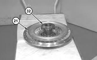

 Illustration 13
g01173867
Illustration 14
g01173868
22. Remove race (28) , rollers (29) , springs (30) , and cam (31) from stator (25) .
Illustration 15
g01173870
Illustration 13
g01173867
Illustration 14
g01173868
22. Remove race (28) , rollers (29) , springs (30) , and cam (31) from stator (25) .
Illustration 15
g01173870
23. Remove spacer (32) from impeller (21) .
24. Use a suitable press to remove carrier shaft (24) from impeller (21) .


Illustration 17
25. Remove bolts (33) and drive gear (34) .
Illustration 16 g01173872 g01173917Illustration 18 g01173920
26. Remove bearing (35) from impeller (21) .


Illustration 19 g01173923
27. Remove seal ring (36) from carrier shaft (23) .
28. If necessary, remove locating dowel (37) .
Illustration 20 g01173921
29. Remove ring (40) , retaining ring (38) , and cover (39) from housing (41) .
Illustration 21
30. Use Tooling (C) in order to remove retaining ring (42) .


Illustration 22
31. Remove spacer (43) and O-ring seal (44) .
Illustration 23
32. Turn the housing onto the opposite side and remove turbine assembly (45) .
Illustration 24
33. Remove bolts (46) in order to separate turbine (47) from hub (48) .


34. If necessary, remove locating dowel (49) .
Illustration 25
35. Remove roller bearing (50) .
Copyright 1993 - 2020 Caterpillar Inc. All Rights Reserved. Private Network For SIS Licensees.
Shutdown SIS
Previous Screen
Product: WHEEL LOADER
Model: 950H WHEEL LOADER M1G
Configuration: 950H Wheel Loader M1G00001-UP (MACHINE) POWERED BY C7 Engine
Disassembly and Assembly
IT62H Integrated Toolcarrier and 950H and 962H Wheel Loaders Power Train
Torque Converter (Freewheel Stator) - Assemble
SMCS - 3101-016
Assembly Procedure Table
1
Required Tools
Note: Cleanliness is an important factor. Before assembly, all parts should be thoroughly cleaned in cleaning fluid. Allow the parts to air dry. Wiping cloths or rags should not be used to dry parts. Lint may be deposited on the parts which may cause later trouble. Inspect all parts. If any parts are worn or damaged, use new parts for replacement.
1. If necessary, install locating dowel (49) .
2. Install bearing (50) so that the notch in bearing (50) is in alignment with locating dowel (49) .
3. Install turbine (47) to hub (48) and install bolts (46) . Tighten bolts (46) to a torque of 60 ± 7 N·m (44 ± 5 lb ft).
Illustration 4
g01173925
5. Install spacer (43) and O-ring seal (44) .
Illustration 5
g01173924
6. Use Tooling (C) to install retaining ring (42) .
Illustration 6
g01173921
7. Install cover (39) , retaining ring (38) , and ring (40) on housing (41) .
Illustration 7
g01173923
8. If necessary, install locating dowel (37) .
9. Install seal ring (36) on carrier shaft (23) .
Illustration 8
g01173920
10. Install bearing (35) in impeller (21) .
Illustration 9 g01173917
11. Install drive gear (34) and bolts (33) . Tighten bolts (33) to a torque of 105 ± 15 N·m (77 ± 11 lb ft).
Illustration 10 g01173872
12. Use a suitable press to install carrier shaft (23) in impeller (21) .
Illustration 11
13. Install spacer (32) on impeller (21) .
g01173870Thank you very much for your reading. Please Click Here. Then Get COMPLETE MANUAL.NOWAITING

NOTE:
If there is no response to click on the link above, please download the PDF document first and then clickonit.
Illustration 12
g01173868
Note: If necessary, raise the temperature of stator (25) in order to install cam (31) .
14. Install cam (31) , springs (30) , rollers (29) , and race (28) in stator (25) .
Note: Install springs (30) with the maximum number of loops toward the outside diameter of cam (31) .
Illustration 13
15. Install washer (27) and retaining ring (26) in stator (25) . Repeat this step for the other side of stator (25) .
g01173867
16. Install stator (25) on impeller (21) .
17. Install spacer (24) and retaining ring (22) over carrier shaft (23) .
18. Install impeller (21) and bolts (20) . Tighten bolts (20) to a torque of 60 ± 7 N·m (44 ± 5 lb ft).
Illustration 14
g01173866
Illustration 15
g01173864
Illustration 16 g03835392
19. Install bearing (19) on output shaft (17) .
20. Install seal ring (18) .
Illustration 17 g01173862
21. Install output shaft (17) and retaining ring (16) .
Illustration 18
22. Install drive gear (15) .
g01173861