
2005 STEERING
Steering Wheel and Column - XLR
SPECIFICATIONS
FASTENER TIGHTENING SPECIFICATIONS
Fastener Tightening Specifications
SCHEMATIC AND ROUTING DIAGRAMS
COLUMN/IGNITION LOCK SCHEMATICS
GENERAL MOTORS CORP.
TILT/TELESCOPING STEERING COLUMN SCHEMATICS
 Fig. 1: Column/Ignition Lock Schematics Courtesy of
of GENERAL MOTORS CORP.
COMPONENT LOCATOR
STEERING COLUMN DISASSEMBLED VIEW
 Fig. 2: Tilt/Telescoping Steering Column Schematics Courtesy
Callouts For Fig. 3
Callout
1 Upper Trim Cover (Kit)
2 Lower Trim Cover (Kit)
Component Name

3 Steering Column Closeout Shroud
4 Flanged Prevailing Torque Nut
5 Retaining Ring
6 SIR Coil
7 Wave Washer
8 Shaft Lock Shield Assembly (Export)
9 Cam Orientation Plate
Fig. 3: Steering Column Disassembled View Courtesy of GENERAL MOTORS CORP.53 Jacket Screw Telescoping Actuator Assembly
54 Pan Head Tapping Screw
55 Pan Head Tapping Screw
56 Telescoping Jacket Assembly
57 Retaining Ring
58 Steering Wheel Position Sensor
59 Sensor Retainer
60 Steering Shaft Seal
61 Intermediate Steering Shaft Assembly
STEERING WHEEL AND COLUMN COMPONENT VIEWS
Callouts For Fig. 4
 Fig. 4: Lower Left of the I/P Component View Courtesy of GENERAL MOTORS CORP.
1 Fuel Door Release Switch
2 Rear Compartment Lid Release Switch - Inside

3 Tilt/Telescope Switch
4 Noise Compensation Microphone
of GENERAL MOTORS CORP.
Callouts For Fig. 5
Callout Component Name
1 Steering Wheel Theft Deterrent Lock (Export)
Fig. 5: Identifying Steering Wheel Theft Deterrent Lock & Tilt Actuator At LR of Steering Column CourtesyCallout Component Name
 Fig. 6: Steering Column Lock Control Module & Telescoping Drive Motor
Courtesy of GENERAL MOTORS CORP.
Callouts For Fig. 6
Fig. 6: Steering Column Lock Control Module & Telescoping Drive Motor
Courtesy of GENERAL MOTORS CORP.
Callouts For Fig. 6

STEERING

Connector Part Information
OEM: 12064760
Service: 12085208
4-Way F Metri-Pack 150 Series (BK) Pin Wire Color Circuit No. Function
A L-GN 1601 Steering Column Lock Signal
B BK 150 Ground
C PU 1604 Steering Column Unlock
D OG 1603 Steering Column Lock
Telescoping Drive Motor Connector End View

Connector Part Information

OEM: 12045688
Service: 12101827
8-Way M Metri-Pack 150 Series (BK)

Connector Part Information
OEM: 12064763
Service: 12101876
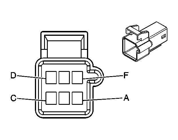
6-Way M Metri-Pack 150 Series (GY)
DIAGNOSTIC INFORMATION AND PROCEDURES
DIAGNOSTIC STARTING POINT - STEERING COLUMN
Begin the system diagnosis with the Diagnostic System Check - Vehicle in Vehicle DTC Information. The Diagnostic System Check will provide the following information:
The identification of the control module which commands the system
The ability of the control module to communicate through the serial data circuit
The identification of any stored diagnostic trouble codes (DTCs) and their status
The use of the diagnostic system check will identify the correct procedure for diagnosing the system and where the procedure is located.
Scan Tool Output Controls
Scan
Tool Output Control
Column Lock Relay On/Off
Default Position Recall/Cancel
Memory 1 Exit Position Recall/Cancel
Memory 1 Position Recall/Cancel
Memory 2 Exit Position Recall/Cancel
Memory 2 Position Recall/Cancel
The DPM can be commanded by using the scan tool to calibrate the tilt/telescope steering wheel. This must be done every time the DPM or the tilt/telescope actuators are replaced.
The BCM can be commanded by using the scan tool to energize the column lock enable circuit.
The DPM can be commanded by using the scan tool to command the tilt/telescope steering wheel to the default position.
The DPM can be commanded by using the scan tool to command the tilt/telescope steering wheel to the number 1 exit position in the DPM memory.
The DPM can be commanded by using the scan tool to command the tilt/telescope steering wheel to the number 1 position in the DPM memory.
The DPM can be commanded by using the scan tool to command the tilt/telescope steering wheel to the number 2 exit position in the DPM memory.
The DPM can be commanded by using the scan tool to command the tilt/telescope steering wheel to the number 2 position in the DPM memory.
SCLCM Setup -
The SCLCM can be commanded by the scan tool to be programmed to the installed vehicle. The module will then only work on the vehicle that it was programmed. This procedure is only necessary when installing a new module.
Telescope Motor Forward/Rearward
Tilt Motor Up/Down
SCAN TOOL DATA LIST
The DPM can be commanded by using the scan tool to command the tilt/telescope steering wheel forward or rearward.
Scan Tool Parameter Data List Units Displayed Typical Data Value Turn the Ignition ON, with the Engine OFF Battery Voltage Signal SCLCM Volts 12.6 V Column Feedback Signal SCLCM Volts 11.9 V Column Lock Enable Signal SCLCM Enabled/Disabled Enabled Column Lock Module Status SCLCM Enabled/Disabled Enabled Column Lock Motor Command SCLCM Lock/Unlock/Idle/Invalid Unlock 2005 STEERING Steering Wheel and Column - XLR
DPM Scan Tool Data List
BCM Scan Tool Data List
SCAN TOOL DATA DEFINITIONS
SCLCM Scan Tool Data Definitions
The steering column lock control module (SCLCM) Scan Tool Data Definitions contains a brief description of all steering column related SCLCM parameters available on the scan tool.
Battery Voltage Signal
The scan tool displays 0-20 volts. The scan tool displays the voltage as received on the battery positive voltage circuit of the module.
Column Feedback Signal
The scan tool displays 0-5 volts. This data represents the signal received on the column lock motor signal circuit.
Column Lock Enable Signal
The scan tool displays Enabled or Disabled. This signal determines whether or not the body control module (BCM) is allowing the SCLCM to function.
Column Lock Module Status
The scan tool displays Enabled or Disabled, whether or not the SCLCM is functioning.
Column Lock Motor Command
The scan tool displays Lock, Unlock, or No Action. This data shows what the SCLCM is commanding the column lock motor.
Column Lock Motor Status
The scan tool displays Lock, Unlock, No Action, or Undefined. This data shows what the column lock motor is doing.
Column Lock Status
The scan tool displays the current column lock state. This data represents what column lock functional mode the SCLCM is in. The SCLCM enters different column lock states based upon information received from various inputs associated with the column lock system.
Ignition Voltage Signal
The scan tool displays ON or OFF. When the SCLCM detects ignition is present, the scan tool will display On. When the SCLCM does not detect ignition, the scan tool will display OFF. This ignition switch information is hard wired into the SCLCM.
Park Switch
The scan tool displays On or Off. When the transmission is placed in PARK the scan tool displays On and when the transmission is out of PARK the scan tool displays Off.
Password Status
The scan tool displays Valid, Invalid, or Not Programmed. The SCLCM compares the password it has to the password in the remote control door lock receiver (RCDLR) via class 2. When the password is the same then the scan tool displays Valid and when the password is different then the scan tool displays Invalid. When the SCLCM is has not been programmed the seed and key procedure to program the module has not been performed.
DPM Scan Tool Data Definitions
The driver position module (DPM) Scan Tool Data Definitions contains a brief description of all steering column related DPM parameters available on the scan tool.
Default Telescope Exit Position
The scan tool displays the default voltage value for the telescope operation in the exit position.
Default Tilt Exit Position
The scan tool displays the default voltage value for the tilt operation in the exit position.
Memory 1 Telescope Exit Position
The scan tool displays 0-5 volts. The value displayed is the telescope sensor voltage stored by the DPM and is used to recall the telescope exit position for driver 1.
Memory 1 Telescope Position
The scan tool displays 0-5 volts. The value displayed is the telescope sensor voltage stored by the DPM and is used to recall the telescope position for driver 1.
Memory 1 Tilt Exit Position
The scan tool display 0-5 volts. The value displayed is the tilt sensor voltage stored by the DPM and is used to recall the tilt exit position for driver 1.
Memory 1 Tilt Position
The scan tool displays 0-5 volts. The value displayed is the tilt sensor voltage stored by the DPM and is used to recall the tilt position for driver 1.
Memory 2 Telescope Exit Position
The scan tool displays 0-5 volts. The value displayed is the telescope sensor voltage stored by the DPM and is used to recall the telescope exit position for driver 2.
Memory 2 Telescope Position
The scan tool displays 0-5 volts. The value displayed is the telescope sensor voltage stored by the DPM and is used to recall the telescope position for driver 2.
Memory 2 Tilt Exit Position
The scan tool display 0-5 volts. The value displayed is the tilt sensor voltage stored by the DPM and is used to recall the tilt exit position for driver 2.
Memory 2 Tilt Position
The scan tool displays 0-5 volts. The value displayed is the tilt sensor voltage stored by the DPM and is used to recall the tilt position for driver 2.
Telescope Forward Command
The scan displays On or Off. The scan tool displays On when the DPM commands the telescope actuator forward.
Telescope Forward Switch
The scan tool displays Active or Inactive. When the switch is pressed to the forward position the scan tool displays Active. When the switch is not depressed forward the scan tool displays Inactive.
Telescope Rearward Command
The scan displays On or Off. The scan tool displays On when the DPM commands the telescope actuator rearward.
Telescope Rearward Switch
The scan tool displays Active or Inactive. When the switch is pressed to the rearward position the scan tool displays Active. When the switch is not depressed rearward the scan tool displays Inactive.
Telescope Sensor
The scan tool displays 0-5 volts. The value displayed is the telescope sensor signal voltage. This voltage varies when the steering column is moved forward or rearward and is used by the DPM to determine the steering column position when memory settings are stored and recalled.
Tilt Down Command
The scan displays On or Off. The scan tool displays On when the DPM commands the tilt actuator down.
Tilt Down Switch
The scan tool displays Active or Inactive. When the switch is pressed to the down position the scan tool
displays Active. When the switch is not depressed down the scan tool displays Inactive.
Tilt Sensor
The scan tool displays 0-5 volts. The value displayed is the tilt sensor signal voltage. This voltage varies when the steering column is moved up or down and is used by the DPM to determine the steering column position when memory settings are stored and recalled.
Tilt Up Switch
The scan tool displays Active or Inactive. When the switch is pressed to the up position the scan tool displays Active. When the switch is not depressed up the scan tool displays Inactive.
BCM Scan Tool Data Definitions
The Body control module (BCM) Scan Tool Data Definitions contains a brief description of all steering column related BCM parameters available on the scan tool.
Column Lock Relay Command
The scan tool displays On/Off. The state displayed is the command state of the lock enable relay. This function is controlled by the BCM with data from the remote control door lock receiver (RCDLR).
Column Lock Relay Signal
The scan tool displays On/Off. The state displayed is the actual state of the lock enable relay. This function is controlled by the BCM with data from the RCDLR.
DTC B0005
Circuit Description
The steering column lock control module (SCLCM) receives a discrete input from the automatic transmission shift lever and a serial data input from the body control module (BCM). When the shift lever is in the park position, the switch internal to the automatic transmission shift lever closes sending a high input to the SCLCM. The SCLCM compares the serial data input to the discrete input. If the SCLCM receives a column lock enable command from the BCM and the transmission shift select switch park signal circuit is low, DTC B0005 will set.
DTC Descriptor
This diagnostic supports the following DTC:
DTC B0005 In Park Switch
Conditions for Running the DTC
DTCs B1327 or B1328 are not set as current.
The condition must be present for 300 ms.
The condition must be present for 5 consecutive ignition cycles.
Conditions for Setting the DTC
DTC B0005 will set when the SCLCM receives a column lock enable command from the BCM and the transmission shift select switch park signal circuit is low.
There is a short to ground, or an open in the transmission shift select switch park signal circuit.
Action Taken When the DTC Sets
DTC B0005 is stored in the SCLCM memory.
The SCLCM will command the driver information center (DIC) to display the Service Column Lock Now message.
Conditions for Clearing the MIL/DTC
The SCLCM no longer detects a malfunction in the transmission shift select park signal circuit.
A history DTC will clear after 50 consecutive ignition cycles if the condition for the malfunction is no longer present.
DTC B0005
Did you perform the Diagnostic System CheckVehicle?
2
1.Turn ON the ignition, with the engine OFF.
2.Observe the Park Switch parameter in the SCLCM data list with a scan tool.
Go to Step 3 System OK 3
Does the scan tool display OFF?
Test the transmission shift select switch park signal circuit for an open or short to ground. Refer to Circuit Testing and Wiring Repairs in Wiring Systems.
Did you find and correct the condition?
Inspect for poor connections at the harness connector of the steering column lock control module (SCLCM).
Go to Step 6 Go to Step 4 4
Refer to Testing for Intermittent Conditions and Poor Connections and Connector Repairs in Wiring Systems.
Did you find and correct the condition?
Go to Step 6 Go to Step 5