
GENERAL SPECIFICATION

Manual & Power Rack & Pinion - Rio
SPECIAL SERVICE TOOLS
2: Steering System Special Service Tools

TROUBLESHOOTING GUIDE
MANUAL STEERING
Fig.
 Fig. 3: Manual Steering Troubleshooting Guide (1 Of 2)
Fig. 4: Manual Steering Troubleshooting Guide (2 Of 2)
POWER STEERING
 Fig. 5: Power Steering Troubleshooting Guide (1 Of 2)
MANUAL STEERING SYSTEM
DESCRIPTION
The manual rack-and-pinion steering gear is sealed against the entry of water or foreign material by rubber boots enclosing the tie rod inboard ends at each end of the housing and by a third boot surrounding the pinion shaft and steering column intermediate shaft. The steering gear is lubricated at assembly and must be removed and disassembled if lubrication becomes necessary.

The rack is positioned and guided in the housing by a bushing at the right end and a support yoke holding it in engagement with the pinion at the left end. The support yoke is spring-loaded against the rack. A yoke plug and lock nut keeps the rack fully engaged with the pinion under load.
Rubber insulating mounts at each end of the housing cushion the steering gear mounting points and minimize vibration. Looseness or deterioration of the mounts can cause noise and vibration problems. These should be checked when investigating for such concerns.
Fig. 6: Power Steering Troubleshooting Guide (2 Of 2)SERVICE ADJUSTMENT PROCEDURE

FREE PLAY INSPECTION
With the ignition OFF and the wheels in the straight ahead position, turn the steering wheel left and right until wheel resistance is felt. Free play should not exceed 1.18 inches (30 mm) at the wheel rim.
Fig. 7: Identifying Manual Steering System ComponentsFig. 8: Testing Wheel Free Play
Excessive free play indicates wear in the steering column intermediate shaft universal joints, worn tie rod ends or ball joints, or improper steering gear preload.
To check the steering column joints, grip or feel the lower joint at the floorboard and repeat the free play check. Any free play between the steering wheel and the lower joint at the floorboard, which is clamped to the pinion shaft, is in the steering column assembly.
Check the tie rods by raising both wheels off the floor. Check each wheel for wobble. First, check the wheels vertically to verify that front wheel bearings are correctly adjusted; then, check the wheels horizontally while an assistant grips the steering column lower joint from inside the vehicle. If horizontal wobble is present, check the tie rod ends for free play or loose attachment to the steering knuckles. If no free play is detected at the tie rod ends, any horizontal wheel wobble must be the result of worn tie rods, ball joints, or excessive gear free play between steering gear rack and pinion. In either case the steering gear must be removed, and adjusted, repaired

STEERING WHEEL EFFORT
1.Raise the road wheels clear of the floor and position jack stands under the lower control arms, as close to the wheels as possible without interfering with steering travel.
2.Turn the steering wheel lock-to-lock at least five times to free up any stickiness resulting from front suspension components being out of their normal riding positions, then place the wheels in the straight ahead position.
3.Attach spring scale to the steering wheel rim and measure the steering effort through one full turn of the wheel.
NOTE:For accurate readings, always pull the scale in the direction the point of scale attachment is moving (tangential to the wheel rim) through the full circle.
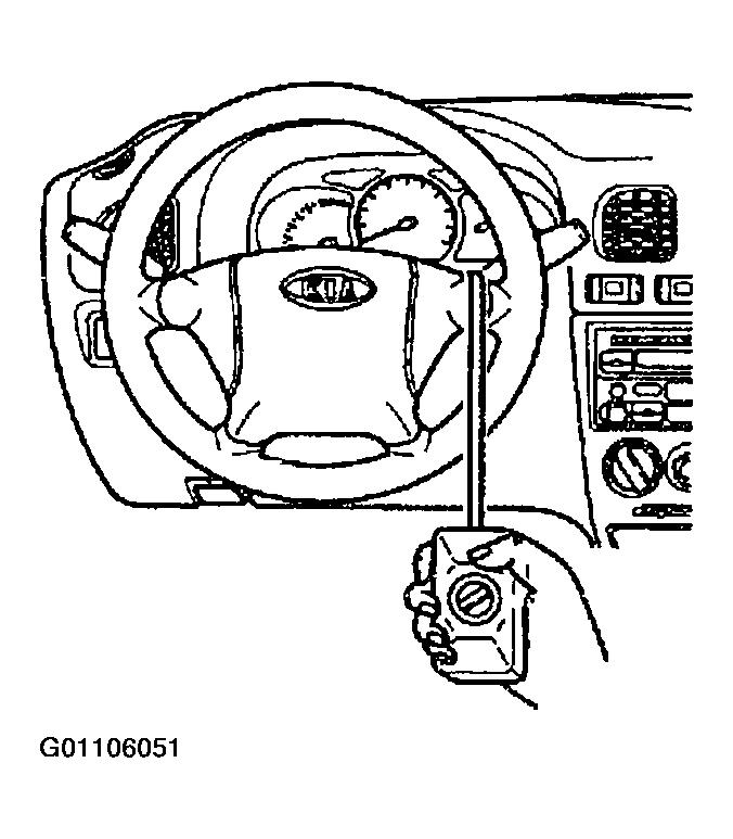
4.Steering effort should be approximately 5~20 N (0.5~2.0 kg, 1~4.5 lb) through a full revolution in either direction from the straight ahead position.
5.If excessive, check for binding or damage in the front suspension and the steering linkage components. Check for excessive steering gear preload.
Fig. 9: Measuring Steering Effort