Shutdown SIS
Previous Screen
Product: COMPACT WHEEL LOADER
Model: 904B COMPACT WHEEL LOADER B4L
Configuration: 904B Compact Wheel Loader B4L00001-UP (MACHINE) POWERED BY S4Q2T Engine
Disassembly and Assembly
904B Wheel LoaderPower Train
Piston Pump (Hydrostatic) - Remove
SMCS - 3203-011
Removal Procedure
Start By:
A. Remove the seat. Refer to Disassembly and Assembly, "Seat - Remove".
B. Remove the gear pump. Refer to Disassembly and Assembly, "Gear Pump - Remove".
Personal injury can result from hydraulic oil pressure and hot oil.
Hydraulic oil pressure can remain in the hydraulic system after the engine has been stopped. Serious injury can be caused if this pressure is not released before any service is done on the hydraulic system.
Make sure all of the attachments have been lowered, oil is cool before removing any components or lines. Remove the oil filler cap only when the engine is stopped, and the filler cap is cool enough to touch with your bare hand.
NOTICE
Care must be taken to ensure that fluids are contained during performance of inspection, maintenance, testing, adjusting and repair of the machine. Be prepared to collect the fluid with suitable containers before opening any compartment or disassembling any component containing fluids.
Refer to Special Publication, NENG2500, "Caterpillar Tools and Shop Products Guide", for tools and supplies suitable to collect and contain fluids in Caterpillar machines.
Dispose of all fluids according to local regulations and mandates.
Note: Put identification marks on all lines, on all hoses, on all wires, and on all tubes for installation purposes. Plug all lines, all hoses and all tubes. This helps to prevent fluid loss and this helps to keep contaminants from entering the system.
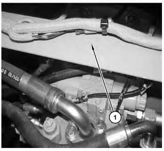 Illustration 1
g01167299
1. Remove plate (1) .
Illustration 1
g01167299
1. Remove plate (1) .
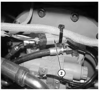
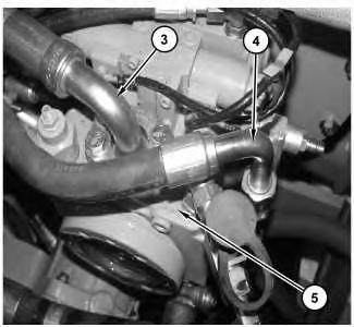 Illustration 2 g01167332
2. Disconnect harness assembly (2) .
Illustration 3 g01167334
3. Disconnect hose assemblies (3) and (4) from piston pump (5) .
Illustration 2 g01167332
2. Disconnect harness assembly (2) .
Illustration 3 g01167334
3. Disconnect hose assemblies (3) and (4) from piston pump (5) .
Illustration 4 g01167336
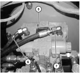 4. Disconnect hose assemblies (6) and (7) from piston pump (5) .
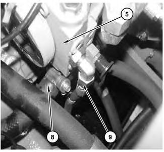
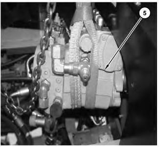
Illustration 5 g01167337
5. Disconnect hose assemblies (8) and (9) from piston pump (5) .
4. Disconnect hose assemblies (6) and (7) from piston pump (5) .
Illustration 5 g01167337
5. Disconnect hose assemblies (8) and (9) from piston pump (5) .
Illustration 6
g01167341
6. Disconnect cable assembly (10) from piston pump (5). Disconnect hose assembly (11) from piston pump (5) .
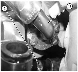
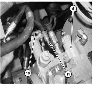
Illustration 7
g01167425
7. Disconnect hose assembly (12) from the bottom of piston pump (5) .
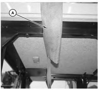
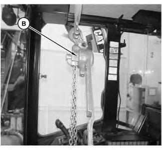 Illustration 8 g01167342
Illustration 9 g01167431
8. Attach Tooling (A) and Tooling (B) to the cab.
Illustration 8 g01167342
Illustration 9 g01167431
8. Attach Tooling (A) and Tooling (B) to the cab.
Illustration 10 g01167343
9. Attach Tooling (B) and a suitable lifting device to piston pump (5) .
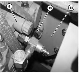
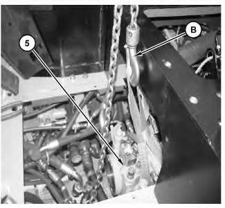
Illustration 11 g01167344
10. Use Tooling (C) in order to remove mounting bolts (13) from piston pump (5) and mounting flange (14) .
Illustration 12
g01167346
11. Raise piston pump (5) in order to remove the pump from the machine. The weight of piston pump (5) is approximately 45 kg (100 lb).
Copyright 1993 - 2019 Caterpillar Inc. All Rights Reserved. Private Network For SIS Licensees.
Sat
Shutdown SIS
Previous Screen
Product: COMPACT WHEEL LOADER
Model: 904B COMPACT WHEEL LOADER B4L
Configuration: 904B Compact Wheel Loader B4L00001-UP (MACHINE) POWERED BY S4Q2T Engine
Disassembly and Assembly
904B Wheel LoaderPower Train
Piston Pump (Hydrostatic) - Disassemble
SMCS - 3203-015
Disassembly Procedure Table 1
Required Tools
Start By:
A. Remove the hydraulic drive pump. Refer to Disassembly and Assembly, "Hydraulic Drive Pump - Remove".
Personal injury can result from hydraulic oil pressure and hot oil.
Hydraulic oil pressure can remain in the hydraulic system after the engine has been stopped. Serious injury can be caused if this pressure is not released before any service is done on the hydraulic system.
Make sure all of the work tools have been lowered to the ground, and the oil is cool before removing any components or lines. Remove the oil filler cap only when the engine is stopped, and the filler cap is cool enough to touch with your bare hand.
Note: Cleanliness is an important factor. Before the disassembly procedure, the exterior of the component should be thoroughly cleaned. This will help to prevent dirt from entering the internal mechanism. Dirt and contaminants can damage the components of the pump or the motor. All disassembly and assembly procedures must be performed on a clean work surface. Clean all the interior components in clean solvent. Dry all the interior components with compressed air. Plug ports and plug hoses on the machine during repair.
NOTICE
Care must be taken to ensure that fluids are contained during performance of inspection, maintenance, testing, adjusting and repair of the product. Be prepared to collect the fluid with suitable containers before opening any compartment or disassembling any component containing fluids.
Refer to Special Publication, NENG2500, "Caterpillar Tools and Shop Products Guide" for tools and supplies suitable to collect and contain fluids on Caterpillar products.
Dispose of all fluids according to local regulations and mandates.
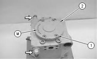
Illustration 1 g00775547 1. Remove bolts (1) and remove charge pump (2) .Illustration 2
g00716074
Note: Mark the location of the charge pump on the head assembly. Crescent (M) of gear set (4) must face toward the valves for installation purposes. The valves are indicated by arrows.
2. Remove O-ring seal (3). Remove gear set (4). Keep the gear set together in order to ensure proper installation of the gear set.
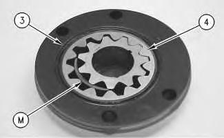
Illustration 3
g00580966
3. Remove bushing (5). Note the orientation of the bushing. The bushing must be installed in the original location.
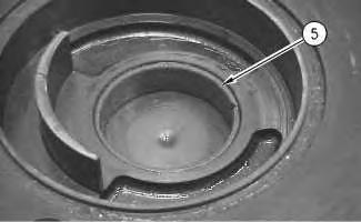
Illustration 4
Illustration 5
Illustration 6
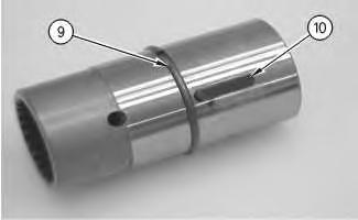
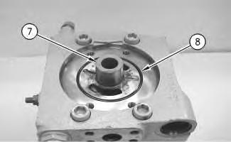
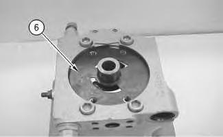
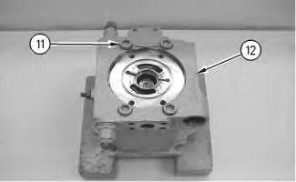
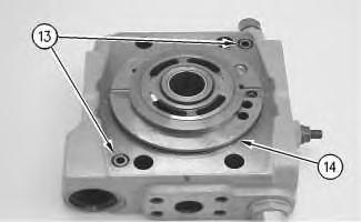
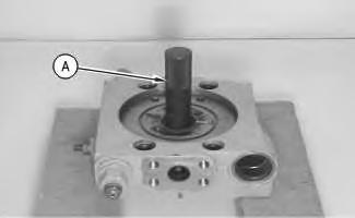 Illustration 7 g00581009
7. Remove bolts (11) and head assembly (12) .
Illustration 8 g00581016
8. Remove O-ring seals (13) and (14) from the head.
Illustration 7 g00581009
7. Remove bolts (11) and head assembly (12) .
Illustration 8 g00581016
8. Remove O-ring seals (13) and (14) from the head.
Illustration 9 g00581023
Illustration 10 g00581022
9. Use Tooling (A) in order to remove bushing (15) .
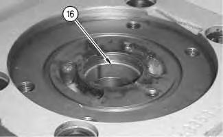
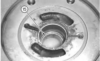
Illustration 11 g00581027
10. Remove bushing (16) .
Note: Mark orientation of groove in bushing (16) for later installation of new bushing into the original location.
Note: Mark the position of the port plate for installation purposes. The groove in the port plate must face the two valves on the head assembly.
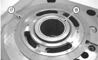
11. Remove port plate (17) and bearing (18), if necessary.
Note: Perform Steps 12 and 13, if equipped.
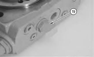 Illustration 12
g00794209
Illustration 13 g00794067
12. Remove plug assembly (19) from the head.
Illustration 12
g00794209
Illustration 13 g00794067
12. Remove plug assembly (19) from the head.
Illustration 14 g00794187
13. Disassemble the plug assembly, as follows: O-ring seal (20), O-ring seal (21) and locking plug (22) .
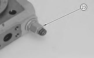
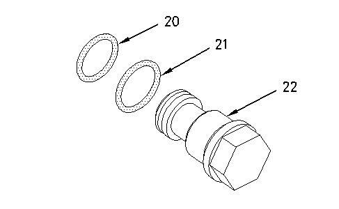
Illustration 15
14. Remove valve (23) from the head.
g00722813
Illustration 16 g00581200
15. Disassemble the valve, as follows: O-ring seal (26), backup ring (25) and O-ring seal (24) .
Illustration 17 g00581207
16. Remove valve (27) from the head. Refer to Step 15 for the disassembly procedure.
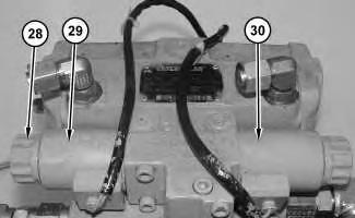
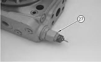
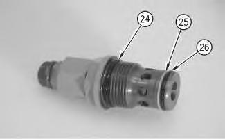 Illustration 18 g01162895
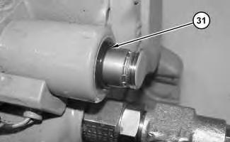
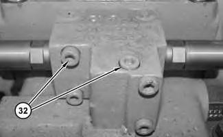
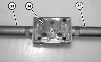 Illustration 19 g01162947
17. Remove caps (28), O-ring seals (31), coil (29), and coil (30) .
Illustration 20 g01162896
18. Remove five bolts (32) .
Illustration 21 g01162948
Illustration 19 g01162947
17. Remove caps (28), O-ring seals (31), coil (29), and coil (30) .
Illustration 20 g01162896
18. Remove five bolts (32) .
Illustration 21 g01162948
Personal injury can result from being struck by parts propelled by a released spring force.
Make sure to wear all necessary protective equipment. Follow the recommended procedure and use all recommended tooling to release the spring force.
19. Remove cartridge (33), cartridge (35), and gasket (34) .
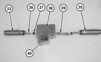
20. Remove springs (36), retainers (37), and spool (39) from housing (38) .
21. Remove O-ring seal (40) .
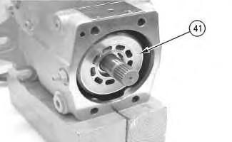
Illustration 22 g01162976 Illustration 23 g00581734 22. Remove barrel assembly (41) from the pump housing. Keep the barrel assembly together with the pistons.Illustration 24
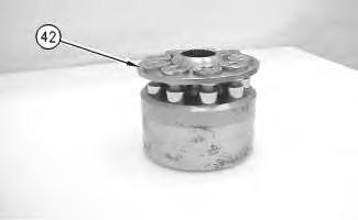
23. Mark the location of the pistons in the barrel assembly. Remove pistons and plate (42) from the barrel assembly.
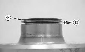
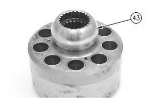
Illustration 25
24. Remove spring retainer (43) .
 g00581740
g00581773
g00581740
g00581773
Personal injury can result from being struck by parts propelled by a released spring force.
Make sure to wear all necessary protective equipment.
Follow the recommended procedure and use all recommended tooling to release the spring force.
Personal injury can result from being struck by parts propelled by a released spring force.
Make sure to wear all necessary protective equipment.
Follow the recommended procedure and use all recommended tooling to release the spring force.
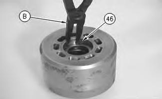
Illustration 28 g00581786
27. Remove washer (47), spring (48), and washer (47) from the barrel assembly.
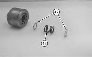
Illustration 29 g00581792
28. Use Tooling (C) in order to remove retaining ring (49) .
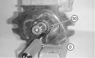
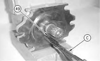
Illustration 30
g00581821
29. Use Tooling (D) in order to remove seal (50) .
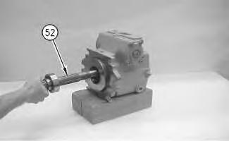
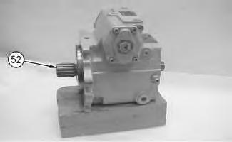
Illustration 31
30. Use Tooling (C) in order to remove retaining ring (51) .
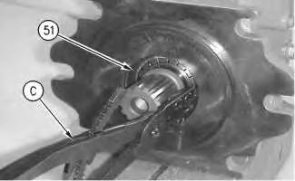
Illustration 32 g00581848
Illustration 33 g00581850
g0058183031. Remove shaft (52). It may be necessary to use a soft faced hammer in order to remove the shaft.
Illustration 34
g00581928
32. Use Tooling (E) in order to remove retaining ring (53) .
Illustration 35
g00581934
33. Use a suitable press in order to remove shaft (52) from bearing (54) .
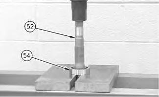
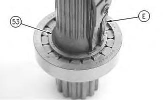
Illustration 36 g00581942
34. Remove swashplate assembly (55) .
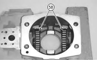
Illustration 37 g00581947
35. Remove plate (56) from the swashplate. Remove rods (57) from the swashplate.
Illustration 38 g00582435
36. Remove bearings (58) .
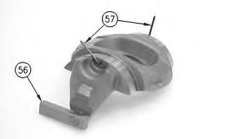
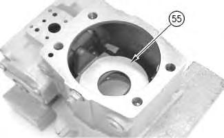
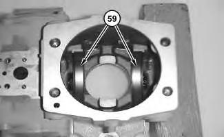
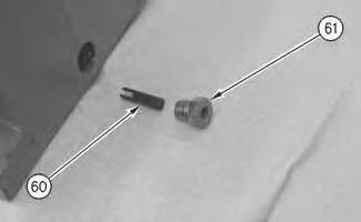
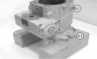 Illustration 39 g01164798
37. Remove bearing cradles (59) .
Illustration 40 g00720021
38. Remove plug (61) and retainer (60) on both sides of the pump housing.
Illustration 39 g01164798
37. Remove bearing cradles (59) .
Illustration 40 g00720021
38. Remove plug (61) and retainer (60) on both sides of the pump housing.
Illustration 41
g00582463
Illustration 42 g00582491
39. Remove bolts (62). Remove cover (63) with valve assembly (64) .
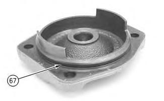
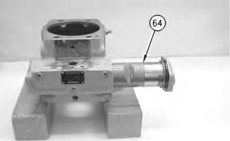
Illustration 43
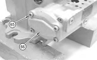
40. Remove bolts (65) and cover (66) .
 g00582495
Illustration 44 g00582504
41. Remove O-ring seal (67) from the cover.
Illustration 45 g00794220
42. Remove nut (68). Unscrew the cover from the valve assembly.
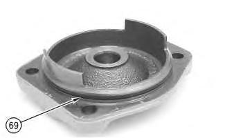
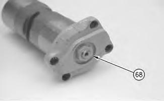
Illustration 46 g00794221
43. Remove O-ring seal (69) .
Suggest:
If the above button click is invalid.
Please download this document first, and then click the above link to download the complete manual.
Thank you so much for reading

Ring (71) is on the opposite end.
Personal injury can result from parts and/or covers under spring pressure.
Spring force will be released when covers are removed. Be prepared to hold spring loaded covers as the bolts are loosened.
45. Use a suitable press to relieve the pressure on the spring. Use Tooling (F) in order to remove retaining ring (73) .
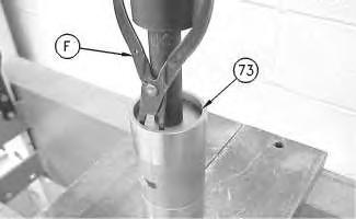
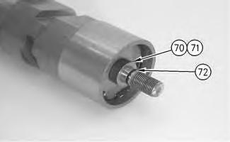 Illustration 47
g00794223
44. Remove O-ring seal (72), and rings (70) and (71) from each side.
Illustration 48
g00582619
Illustration 47
g00794223
44. Remove O-ring seal (72), and rings (70) and (71) from each side.
Illustration 48
g00582619