Service Repair Manual Model 235 EXCAVATOR
Previous Screen
Product: EXCAVATOR
Model: 235 EXCAVATOR 32K
Configuration: 235 EXCAVATOR 32K02679-UP (MACHINE) POWERED BY 3306 ENGINE
Disassembly and Assembly
3304B and 3306B Engines for Caterpillar Built Machines
Governor - Assemble
SMCS - 1264-016
Assembly Procedure
Table 1
Required Tools
Note: Put clean engine oil on all parts before assembly. Ensure that all of the oil passages are clear.
Note: Check the condition of the gaskets and the O-ring seals. If the gaskets, the seals, or any parts are worn or damaged, use new parts for replacement.
NOTICE
Keep all parts clean from contaminants.
Contaminants may cause rapid wear and shortened component life.
1. Install one race (1), bearing (2) and the other race (1) on the camshaft in the fuel injection pump housing.
2. Put flyweights (4) in position on carrier (3) and install the dowels in order to hold the flyweights in place. The flyweights must move freely on the dowels.
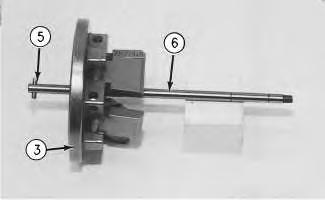
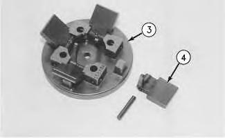
 Illustration 1
g00453799
Illustration 2
g00453801
Illustration 3
g00453802
Illustration 1
g00453799
Illustration 2
g00453801
Illustration 3
g00453802
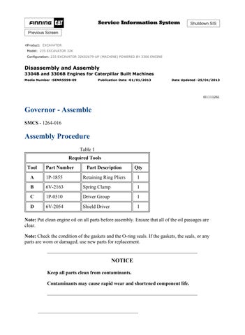
3. Install dowel (5) in governor shaft (6) and install the governor shaft in the carrier (3) .

4. Put carrier (3) in position and install bolts (7) .
5. Install race (9), bearing (10) and race (9). Use Tool (A) in order to install ring (8) on riser (11) .
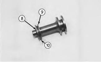 Illustration 4 g00459340
Illustration 5
g00459410
Illustration 4 g00459340
Illustration 5
g00459410
g00459411
6. Install riser (11) .
g00459414
7. Assemble the dashpot, as follows:
a. Install spring (13) on seat (12) and install seat (14) in spring (13) .
b. Put spool (15) and ring (16) in position on seat (14) and use Tool (A) in order to install snap ring (17) .
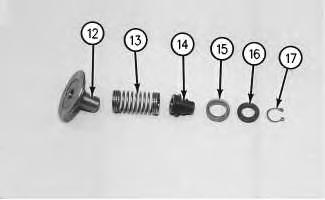
 Illustration 6
Illustration 7
Illustration 6
Illustration 7
Illustration 8
g00459416
8. Install dashpot assembly (19). Install ring (18) in the lower groove in the governor shaft.
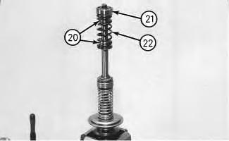
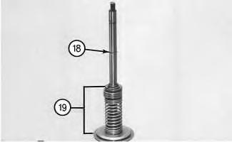
Illustration 9
g00459419
9. Install sleeve (20), spring (22), sleeve (20) and bearing (21) .
Note: Spring (22) is used in order to put a preload on the thrust bearing on the camshaft in the fuel injection pump housing.
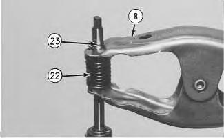
Illustration 10
g00459421
10. Use Tool (B) in order to hold spring (22) compressed and install ring (23) in the groove in the governor shaft. Remove Tool (B) .
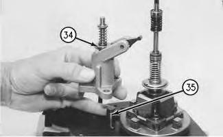
Illustration 11
g00459423
11. Put lever (33) in position on the governor servo and install pin (32) in order to hold the lever in place. Use a hammer and a chisel in order to move the metal (stake) at four places that are spread apart 90 degrees. Perform this procedure on the outside surface on both legs of the governor servo. This helps to hold pin (32) in place.
12. Install the O-ring seal on sleeve (25). Install piston (26) and sleeve (25) .
13. Install valve (24) .
14. Install one lockring (27) in the groove near the center of valve (24). Put sleeve (28), link spring (29) and seat (30) in position on valve (24) and install second lockring (31) .
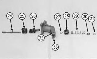
Illustration 12
g00454273
15. Put the governor servo in position on the fuel injection pump housing with piston (34) that is engaged over rack control sleeve (35) and install the bolts that hold the rack control sleeve in place.
Note: The 3304B engine has one stop screw (36) and one locknut (38).
Illustration 14
16. If the stop screws were removed, install two stop screws (36) in collar (37), as shown. Install locknuts (38) .
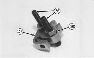
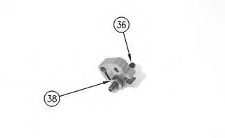 Illustration 13
g00591527
3304B engine
g00454274
3306B
Illustration 13
g00591527
3304B engine
g00454274
3306B
17. Install bolt (41) in block (42), as shown. Install spring (40) on bolt (41), as shown. Put collar (37) in position on bolt (41) with the hole in the collar in alignment with the notch in bolt (41) and install bolt (39) in order to hold the collar in place.

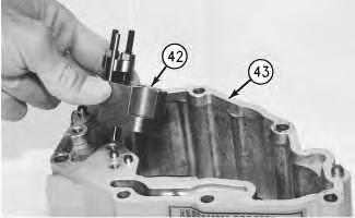
 Illustration 15
g00454275
Illustration 16
g00454428
Illustration 17
g00459548
Illustration 15
g00454275
Illustration 16
g00454428
Illustration 17
g00459548
18. Put block (42) in position on housing (43). Align the holes in block (42) with the dowels. Tighten two bolts (44) .
Illustration 18
3304B torque control
g00590080
19. Assemble the torque control on the 3304B engine. Install retainer (51), two bars (49), spacer (50), contact (46), and insulator (45) in position on bolts (52) .
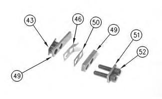
20. Assemble the torque control on the 3306B, as follows:
a. Install spring (48), spacer (47), contact (46) and spacer (50) on insulator (45), as shown.
b. Install retainer (51) and bar (49) on bolts (52) .
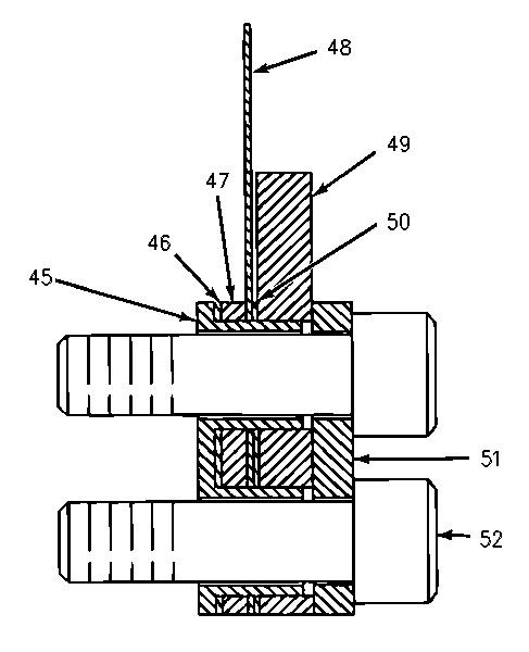
Illustration 20
g00459552
21. Put torque control (53) in position on block (40). Install bolts (54) .
Illustration 21
g00454442
Note: When housing (43) is installed on the fuel injection pump housing, the flange on bolt (38) must be behind the dashpot. If housing (43) is installed with the flange on bolt (38) on the wrong side of the dashpot, the riser in the governor will be held in the maximum fuel delivery position.
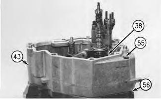
22. Install gasket (56) on the fuel injection pump housing. Put housing (43) in position on the fuel injection pump housing with bolt (38) behind the dashpot, as shown. Install bolts (55) that hold housing (43) in place.
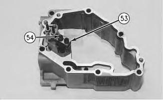
Illustration 22
g00459558
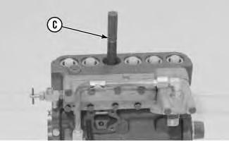
23. Use Tool (C) in order to install lip type seal (57) in the outer governor housing with the lip inward.
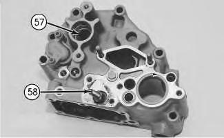
24. Install adjustment screw (58) and the locknut for the high idle adjustment.
Illustration 23
25. Install check valve (59) .
g00459560
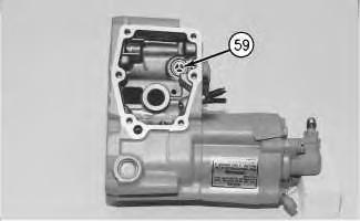
Illustration 24
g00459562
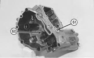
26. Put lever (60) in position, as shown. Install shaft (61) .
Illustration 25
g00459564
27. Put the gasket and shutoff solenoid (62) in position and install two bolts (63) .
28. Put the gasket and cover (64) in position and install two bolts (65) .
29. Install body (66) and contact (67) .
30. Put the O-ring seal on adapter (68) and put the coupling and adapter (68) in position. Install two bolts (69) .
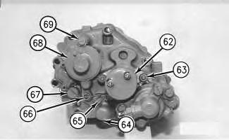
Illustration 26
g00459590
31. Install spring (70) in shaft assembly (71). Install pin (72) in shaft assembly (71). The tip of pin (72) should be engaged in the hole in spring (70). Install pin (73) in shaft assembly (71) in order to hold pin (72) in place.
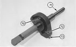
32. Put stop (76) and plates (74) in position on shaft assembly (71) and install pins (75). Install snap rings (77) .
33. Put levers (79) and (78) in position in the housing, as shown. Install shaft assembly (71) .
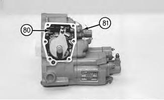
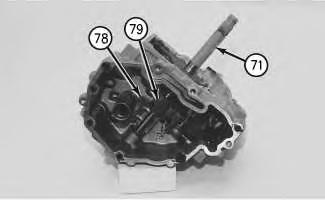
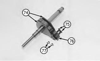 Illustration 27 g00459593
Illustration 28 g00459595
Illustration 29 g00459596
Illustration 27 g00459593
Illustration 28 g00459595
Illustration 29 g00459596
34. Install low idle adjustment screw (81) and the locknut. Install spring (80) in the hole in the shaft assembly and in the housing.
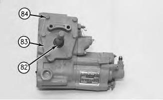
Illustration 30
g00454486
35. Use Tool (C) in order to install lip type seal (82) in cover (83) with the lip, as shown. Install the seal so that the seal is 2.0 ± 1.5 mm (.08 ± .06 inch) below the surface of the cover.
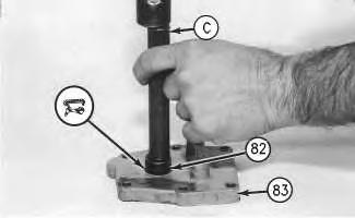
Illustration 31
36. Put the gasket and cover (83) in position on the housing and install six bolts (84) .
g00459597Illustration 32
g00459598
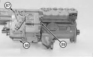
Note: Ensure that seat (85) and spring (86) are on top of lever (79). These parts must be kept in this position when housing (87) is put in position on the inner governor housing.
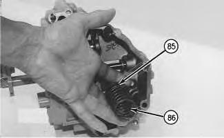
37. Install seat (85) and spring (86) on the guide in the housing.
Illustration 33
g00459600
38. Put the gasket and housing (88) in position on the inner governor housing and install six bolts (87) and two bolts (89) .

Illustration 34
g00459667
39. Install fuel ratio control (90) onto governor (91) .
40. Make the governor adjustments. Refer to the Testing and Adjusting, "Fuel System" topic for more information on governor adjustments.
End By: Install the fuel injection pump housing and the governor. Refer to the Disassembly and Assembly, "Fuel Injection Pump Housing and Governor - Install".
Previous Screen
Product: EXCAVATOR
Model: 235 EXCAVATOR 32K
Configuration: 235 EXCAVATOR 32K02679-UP (MACHINE) POWERED BY 3306 ENGINE
Disassembly and Assembly
3304B and 3306B Engines for Caterpillar Built Machines Media
Fuel Injection Pump - Remove
SMCS - 1251-011
Removal Procedure Table 1
Required Tools
NOTICE
Keep all parts clean from contaminants.
Contaminants may cause rapid wear and shortened component life.
Shutdown SIS
NOTICE
Care must be taken to ensure that fluids are contained during performance of inspection, maintenance, testing, adjusting and repair of the machine. Be prepared to collect the fluid with suitable containers before opening any compartment or disassembling any component containing fluids.
Refer to Special Publication, NENG2500, "Caterpillar Tools and Shop Products Guide", for tools and supplies suitable to collect and contain fluids in Caterpillar machines.
Dispose of all fluids according to local regulations and mandates.
1. Remove the bolts and the plate from the side of the fuel injection pump housing.
2. Install Tool (B) in the fuel injection pump housing. Move the fuel rack until Tool (B) can be installed in order to hold the fuel rack in the center position for removing the fuel injection pumps.
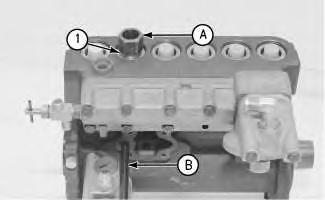
3. Use Tool (A) in order to remove bushing (1) .
4. Remove the O-ring seal from the fuel injection pump housing.
5. Install Tool (C) on the bonnet and remove the fuel injection pump.
Illustration 1 g00455790 Illustration 2 g00455791Illustration 3 g00455792
6. Remove spacer (2) .
Note: Keep spacers (2) and the fuel injection pump together and identify spacers (2) with the location in the fuel injection pump housing.
7. Perform Steps 3 through 6 in order to remove the other fuel injection pumps.
Suggest:
If the above button click is invalid.
Please download this document first, and then click the above link to download the complete manual.
Thank you so much for reading

Previous Screen
Product: EXCAVATOR
Model: 235 EXCAVATOR 32K
Configuration: 235 EXCAVATOR 32K02679-UP (MACHINE) POWERED BY 3306 ENGINE
Disassembly and Assembly
3304B and 3306B Engines for Caterpillar Built Machines
Fuel Injection Pump - Disassemble
SMCS - 1251-015
Disassembly Procedure
Start By:
A. Remove the fuel injection pumps. Refer to Disassembly and Assembly, "Fuel Injection Pump - Remove".
NOTICE
Keep all parts clean from contaminants.
Contaminants may cause rapid wear and shortened component life.
NOTICE
When the fuel injection pumps are disassembled, handle the parts carefully. Do not damage the surfaces of the plungers, the barrels and the bonnets. Any scratches will cause leakage inside the fuel injection pump. The plunger and the barrel for each pump are made as a set. Do not intermix the plunger of one pump in the barrel of another pump. If one part is worn, install a completely new plunger and barrel assembly. Be careful when placing the plunger into the bore of the barrel.