Part number 84516378
English July 2011
Replaces part number 84390833
MANUAL 580N 580SN-WT 580SN 590SN Tractor Loader Backhoe
SERVICE
Contents INTRODUCTION HYDRAULIC, PNEUMA TIC, ELECTRICAL, ELECTRONIC SYSTEMS A PRIMAR Y HYDRAULIC POWER SYSTEM . . . . . . . . . . . . . . . . . . . . . . . . . . . . . . . . . . . . . . . . . . . . . . A.10.A SECONDAR Y HYDRAULIC POWER SYSTEM . . . . . . . . . . . . . . . . . . . . . . . . . . . . . . . . . . . . . . . . . . A.12.A ELECTRICAL POWER SYSTEM . . . . . . . . . . . . . . . . . . . . . . . . . . . . . . . . . . . . . . . . . . . . . . . . . . . . . . . . A.30.A F AUL T CODES . . . . . . . . . . . . . . . . . . . . . . . . . . . . . . . . . . . . . . . . . . . . . . . . . . . . . . . . . . . . . . . . . . . . . . . . . . . A.50.A ENGINE AND O . . . . . . . . . . . . . . . . . . . . . . . . . . . . . . . . . . . . . . . . . . . . . . . . . . . . . . . . . . . . . . . . . . . B ENGINE FUEL AND INJECTION SYSTEM EXHAUST SYSTEM ENGINE COOLANT SYSTEM TING SYSTEM TRANSMISSION, DRIVE AND O OUT . . . . . . . . . . . . . . . . . . . . . . . . . . . . . . . . . . . . . . . . C TRANSMISSION Power Shuttle TRANSMISSION Powershift BRAKES AND STEERING D FRONT AXLE REAR AXLE . . . . . . . . . . . . . . . . . . . . . . . . . . . . . . . . . . . . . . . . . . . . . . . . . . . . . . . . . . . . . . . . . . . . . . . . . . . . . . D.12.A STEERING Hydraulic . . . . . . . . . . . . . . . . . . . . . . . . . . . . . . . . . . . . . . . . . . . . . . . . . . . . . . . . . . . . . . . . . . . . . D.20.C SER VICE BRAKE Hydraulic . . . . . . . . . . . . . . . . . . . . . . . . . . . . . . . . . . . . . . . . . . . . . . . . . . . . . . . . . . . . . . D.30.C
ARKING BRAKE Mechanical
Wheels
AND CAB . . . . . . . . . . . . . . . . . . . . . . . . . . . . . . . . . . . . . . . . . . . . . . . . . . . . . . . . . . . . . . . . . . . . . . . . E FRAME Primary frame . . . . . . . . . . . . . . . . . . . . . . . . . . . . . . . . . . . . . . . . . . . . . . . . . . . . . . . . . . . . . . . . . . . E.10.B SHIELD . . . . . . . . . . . . . . . . . . . . . . . . . . . . . . . . . . . . . . . . . . . . . . . . . . . . . . . . . . . . . . . . . . . . . . . . . . . . . . . . . . . E.20.A USER CONTROLS AND SEA T . . . . . . . . . . . . . . . . . . . . . . . . . . . . . . . . . . . . . . . . . . . . . . . . . . . . . . . . . . E.32.A USER CONTROLS AND SEA T Operator seat . . . . . . . . . . . . . . . . . . . . . . . . . . . . . . . . . . . . . . . . . . . E.32.C USER PLA TFORM 84516378 05/07/201 1
P
WHEELS AND TRACKS
FRAME
ARM T OOL A ACHMENT T ilt
EXCA V A TING AND LANDSCAPING
DIGGING digging tools
CARR YING Articulated tools
ENVIRONMENT CONTROL system FRAME POSITIONING . . . . . . . . . . . . . . . . . . . . . . . . . . . . . . . . . . . . . . . . . . . . . . . . . . . . . . . . . . . . . . . . . F ABILISING W orking stabilising F T OOL POSITIONING . . . . . . . . . . . . . . . . . . . . . . . . . . . . . . . . . . . . . . . . . . . . . . . . . . . . . . . . . . . . . . . . . . . . G LIFTING . . . . . . . . . . . . . . . . . . . . . . . . . . . . . . . . . . . . . . . . . . . . . . . . . . . . . . . . . . . . . . . . . . . . . . . . . . . . . . . . . . G.10.A HITCH AND WORKING T OOL . . . . . . . . . . . . . . . . . . . . . . . . . . . . . . . . . . . . . . . . . . . . . . . . . . . . . . . H BOOM Lift . . . . . . . . . . . . . . . . . . . . . . . . . . . . . . . . . . . . . . . . . . . . . . . . . . . . . . . . . . . . . . . . . . . . . . . . . . . . . . . . H.20.B BOOM Swing . . . . . . . . . . . . . . . . . . . . . . . . . . . . . . . . . . . . . . . . . . . . . . . . . . . . . . . . . . . . . . . . . . . . . . . . . . . . . H.20.D DIPPER Lift . . . . . . . . . . . . . . . . . . . . . . . . . . . . . . . . . . . . . . . . . . . . . . . . . . . . . . . . . . . . . . . . . . . . . . . . . . . . . . . H.25.B
. . . . . . . . . . . . . . . . . . . . . . . . . . . . . . . . . . . . . . . . . . . . . . . . . . . . . . . . . . . . . . . . . . . . . . . H.25.F
DIPPER Extension
. . . . . . . . . . . . . . . . . . . . . . . . . . . . . . . . . . . . . . . . . . . . . . . . . . . . . . . . . . . H.30.C
. . . . . . . . . . . . . . . . . . . . . . . . . . . . . . . . . . . . . . . . . . . . . . . J
. . . . . . . . . . . . . . . . . . . . . . . . . . . . . . . . . . . . . . . . . . . . . . . . . . . . . . . . . . . . . J.50.C 84516378 05/07/201 1

INTRODUCTION 84516378 05/07/201 1 1
Contents INTRODUCTION Safety rules . . . . . . . . . . . . . . . . . . . . . . . . . . . . . . . . . . . . . . . . . . . . . . . . . . . . . . . . . . . . . . . . . . . . . . . . . . . . . . . . . . . . . 3 Safety rules . . . . . . . . . . . . . . . . . . . . . . . . . . . . . . . . . . . . . . . . . . . . . . . . . . . . . . . . . . . . . . . . . . . . . . . . . . . . . . . . . . . . . 4 Safety rules . . . . . . . . . . . . . . . . . . . . . . . . . . . . . . . . . . . . . . . . . . . . . . . . . . . . . . . . . . . . . . . . . . . . . . . . . . . . . . . . . . . . . 5 Safety rules . . . . . . . . . . . . . . . . . . . . . . . . . . . . . . . . . . . . . . . . . . . . . . . . . . . . . . . . . . . . . . . . . . . . . . . . . . . . . . . . . . . . . 6 Battery - Basic instructions . . . . . . . . . . . . . . . . . . . . . . . . . . . . . . . . . . . . . . . . . . . . . . . . . . . . . . . . . . . . . . . . . . . . . 7 ELECTRONIC SYSTEM - Basic instructions . . . . . . . . . . . . . . . . . . . . . . . . . . . . . . . . . . . . . . . . . . . . . . . . . . . 9 Heater - Basic instructions . . . . . . . . . . . . . . . . . . . . . . . . . . . . . . . . . . . . . . . . . . . . . . . . . . . . . . . . . . . . . . . . . . . . Basic instructions 1 1 Basic instructions T orque Abbreviation Measurements Capacities Consumables 84516378 05/07/201 1 2
Safety rules
DANGER
Improper operation service this machine can result accident. not operate this machine perform any lubrication, maintenance, repair until you have read and understood the operation, lubrication, maintenance, and repair information.
Failure comply will result death serious injury
W ARNING
Maintenance hazard!
Always perform all service procedures punctually the intervals stated this This ensures optimum performance levels and maximum safety during machine operation.
Failure comply could result death serious injury .
W ARNING
Pressurized system!
Before attempting any service procedure, your responsibility know the number accumulators the and the correct procedure for releasing the pressure each accumulator
Failure comply could result death serious injury .
NOTICE: Extreme working and environmental conditions require shortened service
Use Case fluids, lubricants, and filters for the best protection and performance your machine. All fluids, lubricants, and filters must disposed compliance with environmental standards and Contact your dealer with any questions regarding the service and maintenance this
Read the safety decals and information decals the Read the Operator ’ s Manual and safety

Understand the operation the machine before you start any
Before you service the put a Not tag the steering wheel over the key Ensure the tag a location where everyone who might operate service the machine may see clearly One tag included with your new machine. Additional tags are available from your dealer .
Plastic and resin parts
• A void using gasoline, paint thinner , etc. when cleaning plastic parts, console, instrument cluster , etc.
• Use only water , mild and a soft cloth when you clean these
• Using gasoline, thinners, etc. can cause discoloration, cracking, deformation the part being cleaned.
INTRODUCTION
D0010A
W0132A
W0136A
84516378 05/07/201 1 3
Safety rules
Before you weld, cut, drill holes any part this machine, make sure the part not cast ductile iron. See your dealer you not know a part cast ductile The following are cast ductile iron parts:
• two wheel drive steering link
• dump links
• front axle
• stabilizers
• extendable dipper
• swing tower
• bucket linkage
Unauthorized modifications cast ductile iron parts can cause injury W drilling can cause cast ductile iron not drill repair attach items cast ductile iron parts this
INTRODUCTION
84516378 05/07/201 1 4
Safety rules
Before welding the machine you must the following. you have any questions about welding the machine contact your dealer
• Disconnect the
• Disconnect the alternator terminal
• Disconnect the instrument cluster
• One connector for mechanical fuel injection engines.
• T connectors for HPCR (high pressure common rail) engines.
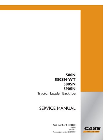
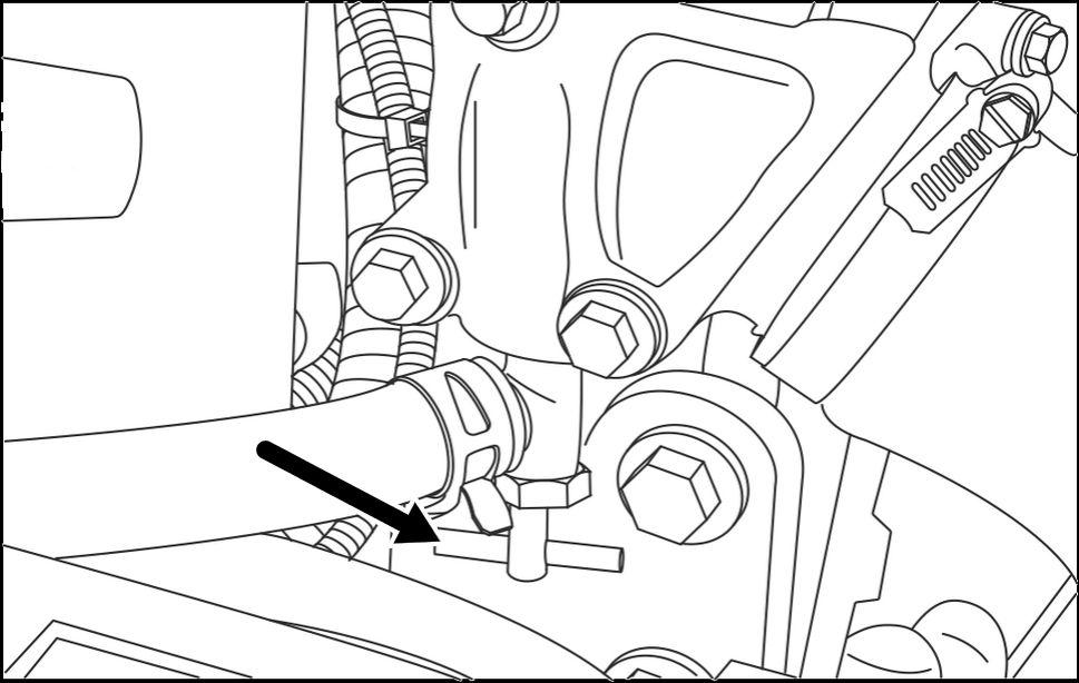
• Disconnect the engine control unit equipped (three
NOTE: The third connector behind the hose the
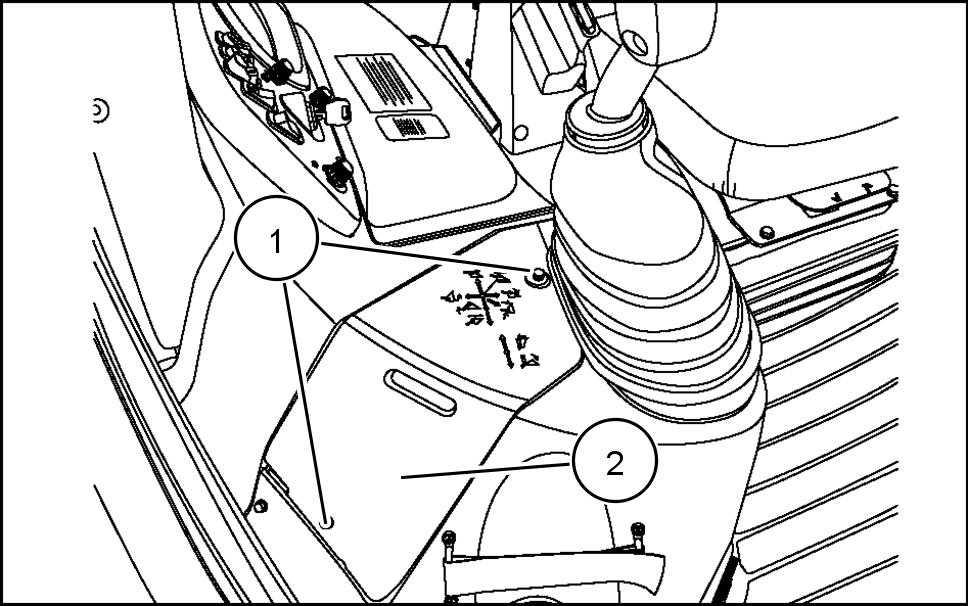
• Disconnect the controller for backhoe pilot controls, equipped (one
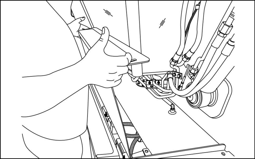
• Disconnect the transmission controller , equipped (one connector , located under the front steering
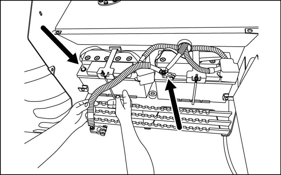
• Disconnect the controller for the loader 4 1 bucket auxiliary equipped (one connector , located under the loader valve the rear , left derside the
INTRODUCTION
1
RCPH10TLB046AAF
84516378 05/07/201 1 5
Safety rules
Unless otherwise instructed, always perform these steps before you service the machine: Park the machine a level
Place the backhoe the transport position with the swing lock pin installed for transport.
Place the loader bucket the with the bottom the loader bucket parallel the
Place the direction control lever and the transmission
you need open the hood perform raise the loader arms and install the support
Shut down the
Place a Not tag the key switch that visible other workers remove the key
INTRODUCTION
84516378 05/07/201 1 6
Battery - Basic instructions
W ARNING
Explosive gas!
Batteries emit explosive hydrogen gas and other fumes while charging. V entilate the charging area. Keep the battery away from sparks, open flames, and other ignition sources. Never charge a frozen battery
Failure comply could result death serious injury . W0005A
W ARNING
Hazardous chemicals!
Battery electrolyte contains sulfuric acid. Contact with skin and eyes could result severe irritation and Always wear splash - proof goggles and protective clothing (gloves and W ash hands after handling.
Failure comply could result death serious injury . W0006A
• not run the engine with the alternator wires
• Before using electric welder , disconnect the alternator instrument cluster and Disconnect the ECU
• not use a steam cleaner a cleaning solvent clean the alternator .
• Keep the battery vents Ensure the battery vents are not
Disconnect Battery
Park the machine a level Raise the loader and lock the support strut hold the loader the upright
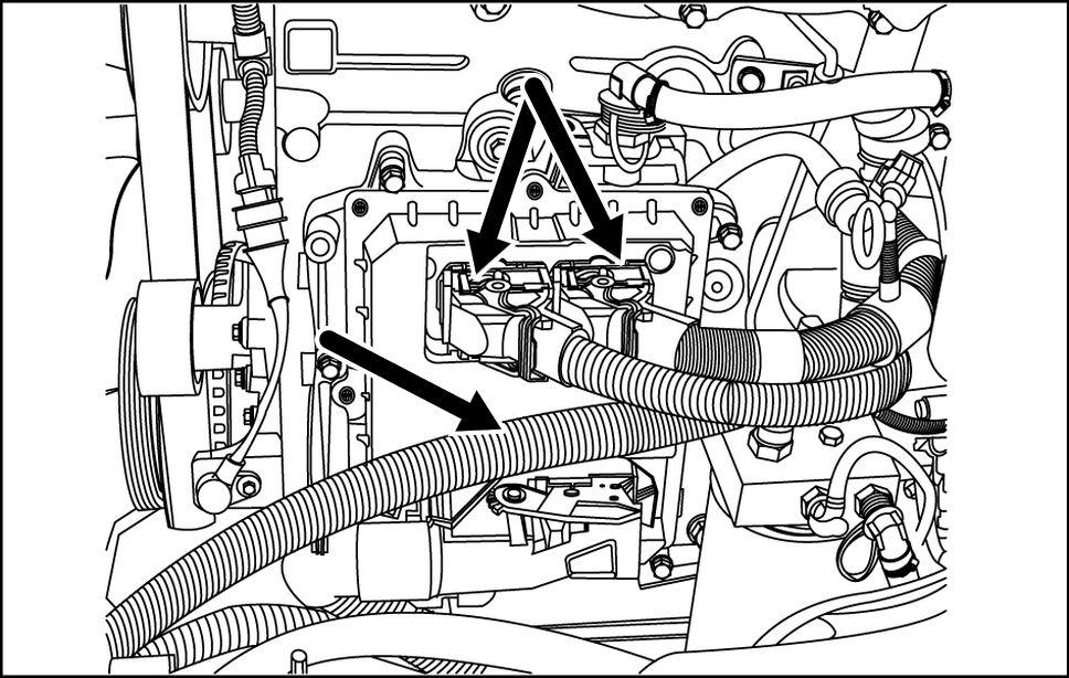
Remove the battery cover
INTRODUCTION
RCPH10TLB022AAL 1
RCPH1 1TLB001AAM 2 84516378 05/07/201 1 7
Remove the battery cover
Disconnect the negative battery cable from the ative battery
INTRODUCTION
RCPH1 1TLB002AAM 3
84516378 05/07/201 1 8
RCPH1 1TLB003AAM 4
ELECTRONIC SYSTEM - Basic instructions
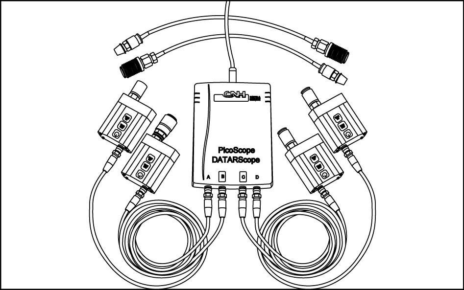
The diagnostic / service tool port located the fuse box the side console. Connect the Electronic Service T ool (EST) T this port update software and / perform service and diagnostic

T urn the thumb screws (1) loosen the panel cover (2) for the fuse Remove the panel cover
RCPH10TLB437AAF 1
Unscrew the cap for the diagnostic / service tool
NOTE: Y not have remove the fuse box covers.
RCPH10TLB302AAF 2
INTRODUCTION
84516378 05/07/201 1 9
Heater - Basic instructions
The heater coolant shutof f valve controls the flow hot coolant the heater
• warm ambient temperatures, turn the shutof f valve clockwise stop hot coolant flow the heater
• cold ambient turn the shutof f valve counter - clockwise allow hot coolant flow the heater
RCPH10TLB159AAF 1
INTRODUCTION
84516378 05/07/201 1
INTRODUCTION
Basic instructions
W ARNING
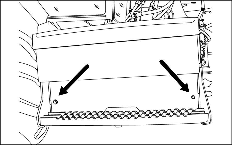
Crushing hazard! you service the machine with the loader lift arms raised, always use the support strut. Remove the retaining pin and place the support strut onto the cylinder rod. Install the retaining pin into the support Lower the lift arms onto the support Failure comply could result death serious injury .
W0230A
Raise and support loader lift arms: Empty the loader bucket.
Raise the loader lift arms the maximum Shut down the engine.
RCPH10TLB230AAF 1
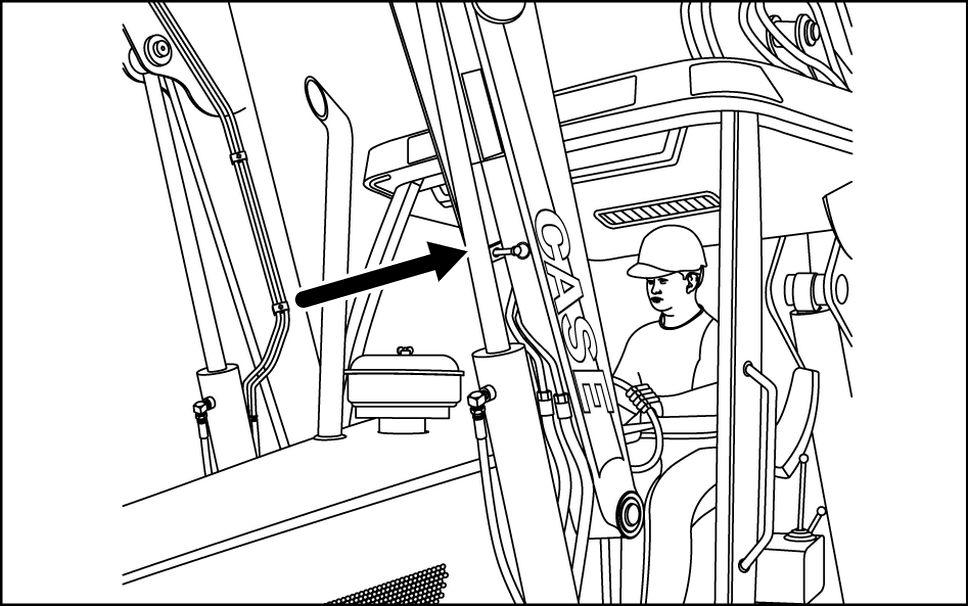
Remove the retaining pin.
Lower the support strut onto the cylinder
Install the retaining pin.
RCPH10TLB221AAF 2
Start the
Slowly lower the lift arms that the end the port strut rests the cylinder .
RCPH10TLB227AAF 3
84516378 05/07/201 1 1 1
Lower supported loader lift arms:
Raise the lift arms that the end the support strut longer rests the cylinder
Shut down the engine.
RCPH10TLB227AAF 4
Remove the retaining pin from the support
Raise the support strut the storage position and secure with the retaining
RCPH10TLB231AAF 5
Start the
Lower the loader the
INTRODUCTION
84516378 05/07/201 1
INTRODUCTION
Basic instructions
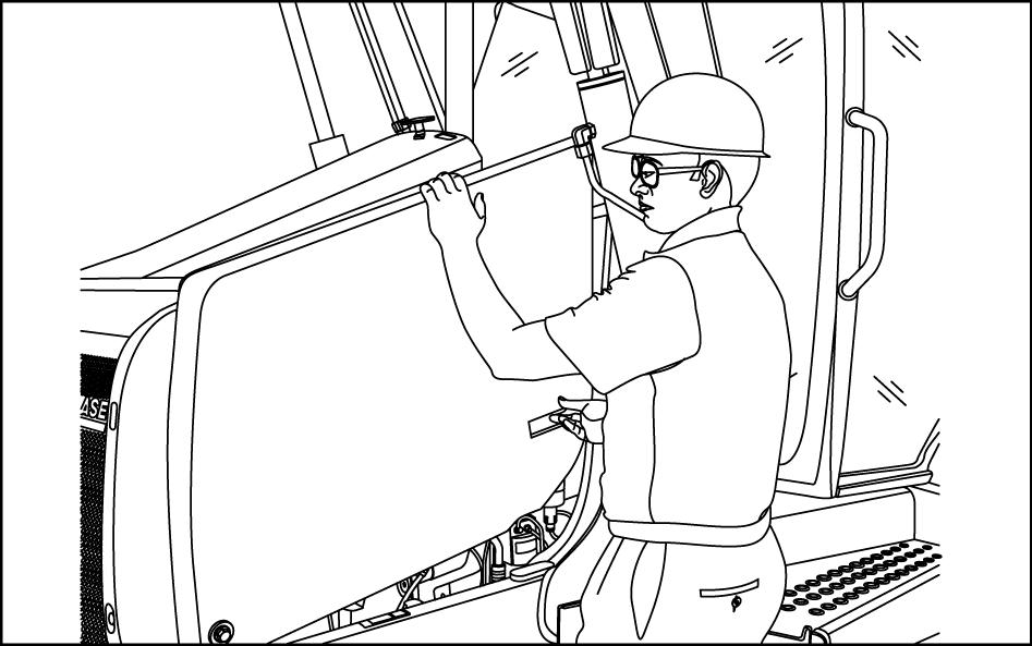
Open the hood: Shut down the
T urn the handle counter - clockwise release the hood
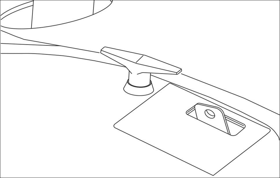
RCPH10TLB166AAF 1 Lift the hood and rotate
RCPH10TLB356AAF 2
NOTICE: T o avoid damage the hood parts, always close the hood before moving the loader .
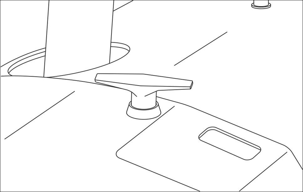
Close the hood: Lower the hood.
T urn the handle clockwise lock the hood
RCPH10TLB167AAF 3
84516378 05/07/201 1
INTRODUCTION


T orque
Use the torques this chart when special torques are not These torques apply fasteners with both UNC and UNF threads received from suppliers dry , when lubricated with engine Not applicable special graphite lubricants, Molydisulfide greases, other extreme pressure lubricants are used.


NOTE: Use thick nuts with Grade 8

Decimal hardware Grade 5 bolts, nuts, and studs Size / 1 / 4 - 108 - 132 5 / - 204 - 252 3 / 8 - 420 - 504 7 / -1 / 2 109 - 1309 / 149 - 179 1 - 132 5 / 8 203 - 244 150 - 180 3 / 4 366 - 439 270 - 324 7 / 8 542 - 651 400 - 480 1 787 - 944 580 - 696 1 - 1 / 8 1085 - 1 193 800 - 880 1 - 1 / 4 1519 - 1681 1 120 - 1240 1 - 3 / 8 1980 - 2278 1460 - 1680 1 - 1 / 2 2631 - 2983 1940 - 2200 Markings for Grade 5 hardware Grade 8 bolts, nuts, and studs Size / 1 / 4 - 144 - 180 5 / - 288 - 348 3 / 8 - 540 - 648 7 / - 11 / 2 149 - 179 1 - 132 9 / 217 - 260 160 - 192 5 / 8 298 - 358 220 - 264 3 / 4 515 - 618 380 - 456 7 / 8 814 - 976 600 - 720 1 1220 - 1465 900 - 1080 1 - 1 / 8 1736 - 1953 1280 - 1440 1 - 1 / 4 2468 - 2712 1820 - 2000 1 - 3 / 8 3227 - 3688 2380 - 2720 1 - 1 / 2 4285 - 4827 3160 - 3560 Markings for Grade 8 hardware
84516378 05/07/201 1
Grade 12.9 bolts, nuts, and studs
/ T ypically the torque values specified for grade 10.9 hardware can used satisfactorily grade 12.9 hardware.


Markings for Grade hardware

Metric hardware Grade 8.8 bolts, nuts, and studs Size / 4 3 - 45 7 - 86 1 1 - - 108 8 - 228 - 276 - 456 - 540 - 107144 - 172 106 - 127 217 - 271 160 - 200 434 - 515 320 - 380 675 - 815 500 - 600 1250 - 1500 920 - 1 100 2175 - 2600 1600 - 1950 Markings for Grade hardware Grade 10.9 bolts, nuts and studs Size / 4 4 - 55 9 - 1 16 - 132 - 156 8 - 324 - 384 -125 - 150 - 1 200 - 245 149 - 179 310 - 380 230 - 280 610 - 730 450 - 540 1050 - 1275 780 - 940 2000 - 2400 1470 - 1770 3500 - 4200 2580 - 3090
for
INTRODUCTION
Markings
Grade hardware
Size
84516378 05/07/201 1
Steel hydraulic fittings 37° flare fitting T ube outside diameter / Hose inside diameter inch Thread size / 1 / 4 7 / - 8 - - 144 7.9 5 / 1 / 2 - 1 1 - - 192 3 / 8 9 / - - 120 - 300 12.7 1 / 2 3 / 4 - - 180 - 504 5 / 6 7 / 8 - - 300 - 696 19.0 3 / 4 1 - 1 / - - 10822.2 7 / 8 1 - 3 / - - 135 - 100 25.4 1 1 - 5 / - 102 - 158 - 1 31.8 1 - 1 / 4 1 - 5 / 8 - 169 - 223 125 - 165 1 - 1 / 2 1 - 7 / 8 - 285 - 338 210 - 250 Straight threads with O - ring T ube outside diameter / Hose inside diameter inch Thread size / 6.4 1 / 4 7 / - - 144 - 228 5 / 1 / 2 - - 192 - 300 9.5 3 / 8 9 / - - 300 - 480 1 / 2 3 / 4 - - 540 - 804 15.9 5 / 6 7 / 8 - - 12419.0 3 / 4 1 - 1 / - 108 - 174 - 128 22.2 7 / 8 1 - 3 / - 136 - 216 100 - 160 25.4 1 1 - 5 / - 159 - 253 1 - 187 1 - 1 / 4 1 - 5 / 8 - 224 - 357 165 - 264 38.1 1 - 1 / 2 1 - 7 / 8 - 339 - 542 250 - 400 Split flange mounting bolts Size / 5 / - - 180 - 240 3 / 8 - - 240 - 300 7 / - - 420 - 540 1 / 2 - -5 / 8 - 1 1 190 - 203 140 - 150 O - ring face seal end T ube outside diameter Nominal SAE dash size Thread size / - 4 1 / 4 9 / - - 120 - 144 - 6 9.5 3 / 8 1 1 / - - 216 - 240 - 8 1 / 2 / - - 384 - 48015.9 5 / 8 1 - - 552 - 67219.0 3 / 4 1 - 3 / - - 122.2 7 / 8 1 - 3 / - - 125.41 1.0 1 - 7 / - 125 - 140 - 105 - 1 - 1 / 4 1 - 1 1 / - 170 - 190 125 - 14038.1 1 - 1 / 2 2 - 200 - 254 150 - 180 84516378 05/07/201 1
INTRODUCTION
O - ring boss end fitting lock nut
INTRODUCTION
T ube outside diameter Nominal SAE dash size Thread size / - 4 6.4 1 / 4 7 / - - 204 - 240 - 6 9.5 3 / 8 9 / - - 300 - 360 - 8 1 / 2 3 / 4 - - 540 - 60015.9 5 / 8 7 / 8 - -- 3 / 4 1 - 1 / - 1 - 12222.2 7 / 8 1 - / - 129 - 136 - 100 - 1 - 5 / - 156 - 169 1 - 12531.8 1 - 1 / 4 - 5 / 6 - 201 - 217 150 - 16038.1 1 - 1 / 2 1 - 7 / 8 - 258 - 271 190 - 200 84516378 05/07/201 1
Abbreviation Measurements
INTRODUCTION
T ypical applications Metric unit Imperial unit Name Symbol Name Symbol Area (Land area) hectare acre square foot ft² square meter square inch in² square millimeter mm² square inch in² Electricity ampere A ampere A volt V volt V microfarad microfarad ohm Ω ohm Ω Force kilonewton pound newton N pound Force per length newton per meter N / m pound per foot / pound per inch / Frequency megahertz MHz megahertz MHz kilohertz kHz kilohertz kHz hertz hertz Frequency − Rotational r / min r / min ª revolution per minute rpm revolution per minute rpm Length kilometer mile meter m foot centimeter inch millimeter inch micrometer Mass kilogram pound gram g ounce milligram Power kilowatt horsepower watt W Btu per hour Btu / Btu per minute Btu / min Pressure stress (Force per area) kilopascal kPa pound per square inch psi inch mercury inHg pascal inch water inH2O megapascal MPa pound per square inch psi 84516378 05/07/201 1
INTRODUCTION T ypical applications Metric unit Imperial unit Name Symbol Name Symbol T emperature (other than Thermodynamic) degrees Celsius degrees Fahrenheit T ime hour h hour h minute min minute min second s second s T orque (includes Bending moment, Moment force, and Moment a couple) newton meter N m pound foot pound foot V elocity kilometer per hour / h mile per hour mph meter per second m / s foot per second / s millimeter per second / s inch per second / s meter per minute m / min foot per minute / min V olume (includes Capacity) cubic meter mm³ cubic yard yd³ liter l cubic inch in³ liter l gallon gal gallon gal quart quart milliliter fluid ounce V olume per time (includes Discharge and Flow rate) cubic meter per minute / min cubic foot per minute ft³ / min liter per minute l / min gallon per minute gal / min milliliter per minute / min gallon per minute gal / min Sound power level and Sound pressure level decibel decibel 84516378 05/07/201 1
INTRODUCTION
Capacities
crank case
Engine
Specification: Case Akcela 1 15W - API - 4 / Capacity: With filter change 13.6 l ( 14.4 ) Fuel tank Specification: No. 2 diesel Capacity: 159 l ( gal ) Cooling system Specification: % water and % ethylene glycol Capacity: 580N Without heater 16.1 l ( 17.0 ) With heater l ( ) 580SN, 590SN Without heater 17.3 l ( 18.3 ) With heater 18.0 l ( 19.0 ) Hydraulic system Specification: Case Akcela - T ran® Ultra Capacity: 580N T otal system l ( 1 ) T otal system with Extendahoe 1 1 1.7 l ( 1 18.0 ) Reservoir with filter change 47.1 l ( 12.45 gal ) Reservoir without filter change 45.2 l ( 1 1.95 gal ) 580SN T otal system 1 l ( 126 ) T otal system with Extendahoe 124.9 l ( 132 ) Reservoir with filter change 47.1 l ( 12.45 gal ) Reservoir without filter change 45.2 l ( 1 1.95 gal ) 580SNT otal system l ( 132 ) T otal system with Extendahoe 130.6 l ( 138.0 ) Reservoir with filter change 47.1 l ( 12.45 gal ) Reservoir without filter change 45.2 l ( 1 1.95 gal ) 590SN T otal system 132 l ( 139 ) T otal system with Extendahoe 137.7 l ( 145 ) Reservoir with filter change 47.1 l ( 12.45 gal ) Reservoir without filter change 45.2 l ( 1 1.95 gal ) 84516378 05/07/201 1
T ransmission
Front drive axle - T wheel drive
Front drive axle - Four wheel drive
Brake master cylinder
fluid supplied the
INTRODUCTION
Specification: Case Akcela - T ran® Ultra Capacity: Manual (powershuttle) T wheel drive Four wheel drive T otal system l ( ) l ( ) Refill (with without filter change) 10.5 l ( 1 1 ) 13.0 l ( ) Powershift S - type T wheel drive Four wheel drive T otal system 21.7 l ( ) 20.7 l ( ) Refill (with without filter change) l ( ) l ( ) Powershift H - type Four wheel drive only T otal system l ( ) Refill (with without filter change) 1 1.4 l ( )
Specification: Case Akcela T ransaxle SAE 80W140 Capacity: Each hub l ( )
Specification: Case Akcela T ransaxle SAE 80W140 Capacity: 580SN Dif ferential 7.7 l ( 8.1 ) Each planetary hub 0.5 l ( 0.5 ) 580SN, 590SN Dif ferential l ( ) Each planetary hub 1.0 l ( 1.1 ) Rear axle (differential) Specification: Case T ransaxle Akcela Capacity: 580N, 580SN 13.6 l ( 14.4 ) 580SN, 590SN 18.6 l ( 19.7 )
84516378 05/07/201 1
Brake
Consumables
Engine oil recommendations
AKCELA 1 ENGINE OIL 15W - recommended for use your

The recommended oil will lubricate your engine correctly under all operating the recommended oil not available a multi - viscosity grade engine oil, okay use a single grade engine oil the recommended oil
the recommended engine oil not available multiviscosity single only use oil meeting API engine oil service category -
Refer the chart for recommended viscosity ambient air temperature ranges.

NOTE: not put
Performance
Additives other oil ditive products the engine The oil intervals given the operators manual and service chart are cording tests with CASE AKCELA
Dye and black light procedure for detecting oil leaks
Oils and grease have natural phosphors and will illuminate dif ferently under the black bluishbrilliant - anti - greenish - yellow , sealing red Kit
NOTE: Each dye formulated work conjunction with a specific therefore the dyes are not interchangeable and should only used
INTRODUCTION
RCPH10TLB244ACL 1
RCPH10TLB022F 2
part number 380040182 consisting of: Part Number Description Unit measurement Comments Usage 380002254 Black Light V olt Ultra V iolet Light 380002357 Dye - uniglow F2HF ( 0.34 ) Glows Green Black Light Engine Oil / Crankcase 380002358 Dye - uniglow F4HF ( 2.2 ) Glows Y ellow Black Light Hydraulic Oil 380002359 Dye - uniglow 1750 ( 0.34 ) Glows Purple Black Light T ransmission Oil
84516378 05/07/201 1
Prior adding connect the black light the machines battery and investigate suspected
Once suspected leak areas are attempt trace the leak completely the origin.
NOTE: At the origin, the leak should the brightest color
After confirmation the suspected leak, thoroughly clean the area the leak remove any existing Recheck the area with the black light assure the area Good cleaning important for the following reasons:
• Fluids captured threaded joints other cavities will continue show signs leakage unless completely
• Casting surfaces can hold residual
Use the entire contents the bottle dye the system / systems the suspected
Run the unit for 5 minutes and cycle through suspect system functions ensure that the dye available all possible leak

NOTE: The hydraulic oil should heated ( 160 ) , engine normal operating temperature, and transmission should the normal operating range the
Use a clean cloth and wipe the dipstick the inside surface the filler tube each the 3
V
iew traces dyed fluid the cloth under the black light ensure good
Use these 3 samples your baseline when ing the unit with the black
NOTE: High hour engine oil can reduce the tiveness the dye. this event change the oil. A void common
• Fan airflow blowing leaking fluid.
• Gravity pulling leak paths
• When paint a joint not broken, the joint not
NOTE: not necessary change oils after this
RCPH10TLB245ACL 3
INTRODUCTION
84516378 05/07/201 1
Diesel fuel
Use No. 2 diesel fuel the engine this machine. The use other fuels can cause the loss engine power and high fuel
very cold a mixture 1 and 2 diesel fuels temporarily
NOTICE: See your fuel dealer for winter fuel requirements your the temperature the fuel below the cloud point (wax appearance wax crystals the fuel will cause the engine lose power not start.
The diesel fuel used this machine must meet the specifications the chart Specification D975 - the ican Society for T esting and
Fuel Storage
you keep fuel storage for a period you can get foreign material water the fuel storage tank. Many engine problems are caused water the
Keep the fuel storage tank outside and keep the fuel cool Remove water from the storage tainer regular periods
INTRODUCTION
Specifications for acceptable 2 Diesel Fuel API gravity (minimum) Flash point (minimum) ( 140 ) * Cloud point (maximum) - ( - 4 ) * Pour point (maximum) - ( - ) V iscosity (at) ( 190 ) Centistokes (2.0) (4.3) Saybolt Seconds Universal (32) (40)
Refer the Notice this
*
84516378 05/07/201 1

HYDRAULIC, PNEUMA TIC, ELECTRICAL, ELECTRONIC SYSTEMS 580N 580SN 580SN 590SN 84516378 05/07/201 1 A
SER VICE MANUAL
Contents HYDRAULIC, PNEUMA TIC, ELECTRICAL, ELECTRONIC SYSTEMS - A PRIMAR Y HYDRAULIC POWER SYSTEM 580N , 580SN , 580SN , 590SN SECONDAR Y HYDRAULIC POWER SYSTEM 580N , 580SN , 580SN , 590SN ELECTRICAL POWER SYSTEM . . . . . . . . . . . . . . . . . . . . . . . . . . . . . . . . . . . . . . . . . . . . . . . . . . . . . . . . . . A.30.A 580N , 580SN , 580SN , 590SN F AUL T CODES . . . . . . . . . . . . . . . . . . . . . . . . . . . . . . . . . . . . . . . . . . . . . . . . . . . . . . . . . . . . . . . . . . . . . . . . . . . . . A.50.A 580N , 580SN , 580SN , 590SN 84516378 05/07/201 1 A
HYDRAULIC, PNEUMA TIC, ELECTRICAL, ELECTRONIC SYSTEMS - A PRIMAR Y HYDRAULIC POWER SYSTEM10.A 580N 580SN 580SN 590SN 84516378 05/07/201 1 A.10.A / 1
Exploded view Hydraulic Pump 580SN and 590SN
Exploded view - Hydraulic gear pump 580N only
Hydraulic schema Regulated manifold hydraulic Pilot Controls Only
Exploded view - Regulated Pilot Controls only
Exploded view 580N Pilot Machines only
Exploded view 580SN and 590SN machines with pilot controls
Remote valve Component diagram - Pilot control color codes
Drawing Remote Clam V alve for 580SN, 580SN and 590SN with Pilot Controlled Backhoe . . . . . .
Drawing 580N Mechanically Controlled Machines
Drawing 580SN and 590SN Mechanically Controlled Machines
Relief valve
Drawing Swing and - Dir Aux Backhoe Control V alves for 580SN and 590SN Pilot Controlled
Drawing Relief V Loader Backhoe Swing mechanically controlled Backhoes
Drawing Relief V 4000 psi Spike Clipper for Loader V alve 580SN and 590SN machines with mechanical backhoe
Drawing Single Stage Relief V 580 Main Relief with mechanical backhoe controls
Drawing Relief V Main System Dual Stage for 580N with Pilot Controlled Backhoe
Drawing Load Sense Relief V 580N with Pilot Controlled Backhoe
Hydraulic pump
Sectional view Hydraulic 580N only 84516378 05/07/201 1
Contents HYDRAULIC, PNEUMA TIC, ELECTRICAL, ELECTRONIC SYSTEMS - A PRIMAR Y HYDRAULIC POWER SYSTEM10.A TECHNICAL T A PRIMAR Y HYDRAULIC POWER SYSTEM Special tools 6 General specification 6 Accumulator General specification - Ride control Special tools - Ride control FUNCTIONAL T A PRIMAR Y HYDRAULIC POWER SYSTEM Exploded view . . . . . . . . . . . . . . . . . . . . . . . . . . . . . . . . . . . . . . . . . . . . . . . . . . . . . . . . . . . . . . . . . . . . . . . . . . . . 1 1
view -
. . . . . . . . . . . . . . . . . . . . . . . . . . . . . . . . . . . . . . . . . . . . . .
Exploded
Hydraulic gear pump, 580N only
A.10.A / 2
Sectional view Hydraulic 580SN and 590SN with Power Lift
Drawing - Output T est Hose 580SN and 590SN
Drawing Power Lift V alve 580SN and 590SN machines with Mechanical Controls
Drawing Power Lift V alve 580SN and 590SN machines with Pilot Controlled Backhoe Filter
Sectional view Accumulator Exploded view - Ride control . .
Detailed view - Ride control . . . . . . . . . . . . . . .
Control valve
Drawing Backhoe Control V 8 Extendahoe with Pilot 580SN and 590SN machines
Drawing Backhoe Control V alve, 8 Spool, Extendahoe with Pilot Controls, 580N machines . . . . . . . . . .
Drawing Loader V 2 Spool for 580N with mechanical controls
Drawing Loader V 2 Spool for 580N with pilot controls
Drawing Loader V 3 Spool for 580N with mechanical backhoe controls
Drawing Loader V 3 Spool for 580N with pilot controls
Drawing Loader 3 Spool for 580SN and 590SN with mechanical backhoe controls
Drawing Loader V alve, 3 Spool for 580SN, 580SN and 590SN with Pilot Controls . . . . . . . . . . . . . .
Drawing Backhoe V 8 Spool foot swing
Sectional view Stabilizer 580SN and 590SN machines with Pilot Controls
Sectional view Dipper , Extendahoe 580SN and 590SN chines with Pilot Controls . . . . .
Exploded view - Ride control solenoid valve
Exploded view - Boom lock solenoid valve
PRIMAR Y HYDRAULIC POWER SYSTEM
. . . . . . .
. . . .
. . . . . . . . . . . . . . . . . . . . . . . . . . . . . . . . . . . . . . . . . . . . .
.
. . . .
.
. . . . . . . . . . . . . . . . . . . . . . . . . . . . . . . . . . . . . . . . . . . . . . . . .
.
. . . . . . . . . . . . . . . . . . . . . . . . . . . . . . . . . . . . . . . . . . . . . . . . . . . . . . . . . . . . . . . . . . . . . . . . . . . . . . .
.
. . . . . . . . . . . . . . . . . . . . . . . . . . . . . . . . . . . . . . . . . . . . . . . . . . . . . . . . . . . . .
.
. . . . . . . . . . . . . . . . . . . . . . . . . . . . . . . . . . . . . . . . . . . . . . . . .
.
. . . . . . . . . . . . . . . . . . . . . . . . . . . . . . . . . . . . . . . . . . . . . . . . . . . . SER VICE
Cleaning Disassemble - Regulated manifold Assemble - Regulated manifold Prepare - Machine 580N Pilot machines T est Pressure T 580N Pilot machines Check - Flowmeter Check Sheet, 580N Pilot machines . . . . . . . . . . . . . . . . . . . . . . . . . . . . . . . . . . . . . . . . . Prepare - Machine 580N Mechanically Controlled machines T est Pressure T 580N Mechanically Controlled machines Check - Flowmeter Check 580N Mechanically Controlled machines Prepare Machine All 580SN and 590SN machines T est Pressure T All 580SN and 590SN machines Check Flowmeter Check All 580SN and 590SN machines 100 Adjust T orque Control Adjustment, 580SN, 580SN and 590SN machines with Mechanical Controls 103 Adjust T orque Control 580SN and 590SN machines with Pilot Controls 107 Remote valve 84516378 05/07/201 1 A.10.A / 3
Remove - Remote control valves . . . . . . . . . . . . . . . . . . . . . . . . . . . . . . . . . . . . . . . . . . . . . . . . . . . . . . . . . . . 1 1 1 Install - Remote control valves . . . . . . . . . . . . . . . . . . . . . . . . . . . . . . . . . . . . . . . . . . . . . . . . . . . . . . . . . . . . . 1 Remove - Loader control valve . . . . . . . . . . . . . . . . . . . . . . . . . . . . . . . . . . . . . . . . . . . . . . . . . . . . . . . . . . . . . 1 Install - Loader control valve 120 Remove - Clam control pilot valve 124 Install - Clam control pilot valve 125 Remove - Pilot controls backhoe valve 126 Install - Pilot controls backhoe valve 128 Remove - Mechanical controls backhoe valve 130 Install - Mechanical controls backhoe valve 132 Check - Pilot control unit 134 Relief valve Adjust Main Relief V alve, 580N with mechanical controls . . . . . . . . . . . . . . . . . . . . . . . . . . . . . . . . . . . . . . 139 Remove - Circuit relief 580SN and 590SN machines with Pilot Controls (Swing and - Directional relief valves only) 140 Cleaning Relief V alve, Backhoe Main Relief V alve, 580N with Pilot Backhoe Controls . . . . . . . . . . . . . 142 Pressure test Loader and Backhoe Main Relief V alve for 580N mechanical machines only Loader Main Relief V alve for 580N machine with Pilot 143 Pressure test - Load Sense Relief V alve for 580N Backhoe relief Pilot Controls only 144 Adjust - 580N Backhoe relief Pilot Controls only . . . . . . . . . . . . . . . . . . . . . . . . . . . . . . . . . . . . . . . . . . . . . . 145 Adjust Dual Stage Relief V 580N Pilot Controlled Backhoe V alves 146 Replace - Load Sense Relief V alve 147 Hydraulic pump Remove - 580N only 148 Install - 580N only 150 Remove - 580SN - and 590SN 152 Install - 580SN - and 590SN 154 Disassemble - Priority V 580N only 156 Inspect - Priority V 580N only 157 Assemble - Priority V 580N only 158 Prepare W ork Surface 159 Disassemble - Single Section Gear Pump . . . . . . . . . . . . . . . . . . . . . . . . . . . . . . . . . . . . . . . . . . . . . . . . . . . 160 Inspect . . . . . . . . . . . . . . . . . . . . . . . . . . . . . . . . . . . . . . . . . . . . . . . . . . . . . . . . . . . . . . . . . . . . . . . . . . . . . . . . . 164 Assemble - Single Section Gear Pump 165 Assemble 169 580N 580SN , 590SN Disassemble 178 580N 580SN , 590SN Accumulator Check - Ride control 182 Charging - Ride control 183 Discharging - Ride control 184 Disassemble - Ride control 185 Inspect - Ride control 186 Assemble 188 84516378 05/07/201 1 A.10.A / 4
Pressure test Right Solenoid V alve for Ride Control (Accumulator) 191 Pressure test Checking the Nitrogen Charge the Accumulator 193 Charging - Charging the Accumulator With Dry Nitrogen 194 Control valve Cleaning 580N Pilot machines only 195 CleaningSwing, - Dir Aux and Stabilizer sections . . . . . . . . . . . . . . . . . . . . . . . . . . . . . . . . . . . . . . . . . . 199 Cleaning 580SN and 590SN machines 203 Disassemble - Ride control solenoid valve 206 Assemble - Ride control solenoid valve 207 Disassemble - Boom lock solenoid valve 208 Inspect - Boom lock solenoid valve 209 Assemble - Boom lock solenoid valve 210 DIAGNOSTIC PRIMAR Y HYDRAULIC POWER SYSTEM T esting - Problem a loader circuit 1 T esting - Problem the 4x1 Clam Circuit 1 T esting 580N Machines only 212 T esting - Single function will not work independently from other functions 213 T esting 213 T esting 214 T esting - Noise from the backhoe hydraulic system . . . . . . . . . . . . . . . . . . . . . . . . . . . . . . . . . . . . . . . . . . . 214 T esting - All pilot controls stop working . . . . . . . . . . . . . . . . . . . . . . . . . . . . . . . . . . . . . . . . . . . . . . . . . . . . . . 215 T esting - Pilot pattern change does not function 215 T esting - Fault codes for pilot controller 215 Hydraulic pump T esting 217 Reservoir T esting - Hydraulic oil reservoir 218 84516378 05/07/201 1 A.10.A / 5
PRIMAR Y


PNEUMA ELECTRONIC SYSTEMS - PRIMAR Y HYDRAULIC POWER SYSTEM
HYDRAULIC POWER
RCPH10TLB080AAM 1 T CAS10090 2 CAS - 10090 Hand Pump CAS10899 3 CAS - 10899 Charging Kit PRIMAR Y HYDRAULIC POWER SYSTEM - General specification 580N Single Gear Pump Make and Model Parker P330 Single Section Gear Pump Nominal Capacity Hydraulic Pump 580N @ 2200 RPM 1 l / min ( 30.5 gpm ) 108 l / min @ 231 bar ( gpm @ 3350 psi ) Steering Relief Pressure 162±10 / - 0 bar ( 2349.0±50 psi ) Pressure Settings Main Relief V alve 231 bar ( 3350 psi ) ± 3.5 bar ( psi ) Accumulator for ride control (Nitrogen charge) bar ( psi ) ± 1 bar ( psi ) Circuit relief valves (Hand pump setting only) 84516378 05/07/201 1 A.10.A / 6
SYSTEM - Special tools
PNEUMA
580N Single Gear Pump Backhoe bucket A (upper) port 296 bar ( 4293 psi ) ± 3 bar ( 43.5 psi ) Backhoe bucket B (lower) port 283 bar ( 4105 psi ) ± 3 bar ( 43.5 psi ) Swing A (upper) and B (lower) ports 207 bar ( 3000 psi ) ± 3 bar ( psi ) Loader bucket A (upper) and B (lower) ports 221 bar ( 3205 psi ) ± 3 bar ( 43.5 psi ) Boom A (upper) port with Mechanical Controls 221 bar ( 3205 psi ) ± 3 bar ( psi ) Boom A (upper) port with Pilot Controls 230 bar ( 3335 psi ) ± 3 bar ( 43.5 psi ) Boom B (lower) port with Mechanical Controls 340 bar ( 4930 psi ) ± 3 bar ( 43.5 psi ) Boom B (lower) port with Pilot Controls 360 bar ( 5220 psi ) ± 3 bar ( 43.5 psi ) Dipper A (upper) port 283 bar ( 4103 psi ) ± 3 bar ( psi ) Dipper B (lower) port 250 bar ( 3625 psi ) ± 3 bar ( psi ) 580SN W ithout Power Lift Make and Model Bosch Rexroth Series V ariable Displacement Axial Piston Pump Pump Controls Without Power Lift Option: High Pressure Cut - f (HPCO) control pump set 238±3.5 bar ( 3450 ±50 psi ) Nominal Capacity @ 2200 RPM Load: 156 l / min ( gpm ) Loader: 156 l / min @ 161 bar ( gpm @ 2335 psi ) 103 l / min @ 238 bar ( gpm @ 3450 psi ) Backhoe: 156 l / min @ 214 bar ( gpm @ 3100 psi ) 132 l / min @ 238 bar ( gpm @ 3450 psi ) Pump Settings HPCO: 238±3.5 bar ( 3450±50 psi ) Steering relief pressure 162±10 / - 0 bar ( 2349.0±150 - 0 psi ) Standard Main Relief Pressure bar ( 3450±50 psi ) Heavy Lift Main Relief Pressure 250±3.5 bar ( 3625.0±50 psi ) Backhoe bucket A (upper) port 296 bar ( 4292 psi ) ± 3 bar ( 43.5 psi ) Backhoe bucket B (lower) port 283 bar ( 4103 psi ) ± 3 bar ( psi ) Swing A (upper) and B (lower) ports 207 bar ( 3000 psi ) ± 3 bar ( psi ) Loader bucket A (upper) and B (lower) ports 250 bar ( 3625 psi ) ± 3 bar ( 43.5 psi ) Boom A (upper) port with Mechanical Controls 221 bar ( 3205 psi ) ± 3 bar ( 43.5 psi ) Boom A (upper) port with Pilot Controls 230 bar ( 3335 psi ) ± 3 bar ( 43.5 psi ) Boom B (lower) port with Mechanical Controls 340 bar ( 4930 psi ) ± 3 bar ( 43.5 psi ) Boom B (lower) port with Pilot Controls 340 bar ( 4930 psi ) ± 3 bar ( 43.5 psi ) Dipper A (upper) port 283 bar ( 4103 psi ) ± 3 bar ( psi ) Dipper B (lower) port 250 bar ( 3625 psi ) ± 3 bar ( psi ) Swing Relief Pressure 207+7 / 3 bar ( / - psi ) l / min ( 14.0 gpm ) 580SN W ith Optional Power Lift Make & Model Bosch Rexroth Series V ariable Displacement Axial Piston Pump Pump Controls Control with remote Relief V Primary remote relief Power Lift valve for main relief Secondary remote relief Power Lift for Lift" pressure Nominal Capacity @ 2200 RPM Load: 156 l / min ( gpm ) Loader: 156 l / min @ 161 bar ( gpm @ 2335 psi ) 103 l / min @ 238 bar ( gpm @ 3450 psi ) Backhoe: 156 l / min @ 214 bar ( gpm @ 3100 psi ) 132 l / min @ 238 bar ( gpm @ 3450 psi ) 84516378 05/07/201 1 A.10.A / 7
ELECTRONIC SYSTEMS - PRIMAR Y HYDRAULIC POWER SYSTEM
Suggest:
If the above button click is invalid.
Please download this document first, and then click the above link to download the complete manual.
Thank you so much for reading

PNEUMA
580SN W ith Optional Power Lift Power Lift capacity load: 99.3 l / min ( 26.2 gpm ) . Heavy lift capacity: l / min ( gpm ) 250 bar ( psi ) @ 1400 Steering relief pressure 162±10 / - 0 bar ( - 0 psi ) Standard Main Relief Pressure 238±3.5 bar ( 3450±50 psi ) Heavy Lift Main Relief Pressure 250±3.5 bar ( 3625.0±50 psi ) Backhoe bucket A (upper) port 296 bar ( 4292 psi ) ± 3 bar ( psi ) Backhoe bucket B (lower) port 283 bar ( 4103 psi ) ± 3 bar ( 43.5 psi ) Swing A (upper) and B (lower) ports 207 bar ( 3000 psi ) ± 3 bar ( 43.5 psi ) Loader bucket A (upper) and B (lower) ports 250 bar ( 3625 psi ) ± 3 bar ( 43.5 psi ) Boom A (upper) port with Mechanical Controls 221 bar ( 3205 psi ) ± 3 bar ( 43.5 psi ) Boom A (upper) port with Pilot Controls 230 bar ( 3335 psi ) ± 3 bar ( 43.5 psi ) Boom B (lower) port with Mechanical Controls 340 bar ( 4930 psi ) ± 3 bar ( psi ) Boom B (lower) port with Pilot Controls 340 bar ( 4930 psi ) ± 3 bar ( psi ) Dipper A (upper) port 283 bar ( 4103 psi ) ± 3 bar ( 43.5 psi ) Dipper B (lower) port 250 bar ( 3625 psi ) ± 3 bar ( 43.5 psi ) Swing Relief Pressure 207+7 / 3 bar ( / - psi ) l / min ( gpm ) 580SN W ith Standard Power Lift Make & Model Bosch Rexroth Series V ariable Displacement Axial Piston Pump Pump Controls Control with remote Relief V Primary remote relief Power Lift valve for main relief pressure. Secondary remote relief Power Lift for Lift" pressure Nominal Capacity @ 2200 RPM Load: 156 l / min ( gpm ) Loader: 156 l / min @ 161 bar ( gpm @ 2335 psi ) 103 l / min @ 238 bar ( gpm @ 3450 psi ) Backhoe: 156 l / min @ 214 bar ( gpm @ 3100 psi ) 132 l / min @ 238 bar ( gpm @ 3450 psi ) Power Lift capacity @ 1400 RPM load: l / min ( gpm ) Power Lift capacity: l / min ( 14.5 gpm ) 261 bar ( 3780 psi ) @ 1400 Steering relief pressure 162±10 / - 0 bar ( 2349.0±150 - 0 psi ) Standard Main Relief Pressure bar ( 3450±50 psi ) Heavy Lift Main Relief Pressure bar ( psi ) Backhoe bucket A (upper) port 296 bar ( 4292 psi ) ± 3 bar ( 43.5 psi ) Backhoe bucket B (lower) port 283 bar ( 4103 psi ) ± 3 bar ( 43.5 psi ) Swing A (upper) and B (lower) ports 207 bar ( 3000 psi ) ± 3 bar ( psi ) Loader bucket A (upper) and B (lower) ports 250 bar ( 3625 psi ) ± 3 bar ( 43.5 psi ) Boom A (upper) port with Mechanical Controls 221 bar ( 3205 psi ) ± 3 bar ( psi ) Boom A (upper) port with Pilot Controls 230 bar ( 3335 psi ) ± 3 bar ( 43.5 psi ) Boom B (lower) port with Mechanical Controls 340 bar ( 4930 psi ) ± 3 bar ( 43.5 psi ) Boom B (lower) port with Pilot Controls 340 bar ( 4930 psi ) ± 3 bar ( 43.5 psi ) Dipper A (upper) port 283 bar ( 4103 psi ) ± 3 bar ( 43.5 psi ) Dipper B (lower) port 250 bar ( 3625 psi ) ± 3 bar ( psi ) Swing Relief Pressure 207+7 / 3 bar ( / - psi ) l / min ( 14.0 gpm ) 84516378 05/07/201 1 A.10.A / 8
ELECTRONIC SYSTEMS - PRIMAR Y HYDRAULIC POWER SYSTEM