
D7G TRACK-TYPE TRACTOR
Disassembly and Assembly
E
- Disassemble
Procedure
Part Number
1P-2420 Repair Stand
1P-7407 Eyebolt
1P-7405 Eyebolt
1U-7600 Puller Assembly
8B-7548 Puller Assembly 1
8B-7551 Bearing Puller Attachment 1
8B-7549 Leg
8B-7550 Leg
8B-7555 Adapter
8H-0684 Ratchet Box Wrench
8B-7560 Step Plate
F 8B-7548 Puller Assembly
8B-7551 Bearing Puller Attachment
8B-7550 Leg
8H-0684 Ratchet Box Wrench
Shutdown SIS Previous Screen Product: TRACK-TYPE TRACTOR Model: D7G TRACK-TYPE TRACTOR 7MB Configuration: D7G TRACK-TYPE TRACTOR 7MB00001-UP (MACHINE) POWERED BY 3306 ENGINE
D7G and D7G Series II Track-Type Tractors Power Train Media Number -KENR6354-02 Publication Date -01/09/2008 Date Updated -22/09/2008 i02627420 Transmission
SMCS - 3030-015 Disassembly
Table 1 Required Tooling Tool
Part Description Qty A
1 B
2 C
3 D
1
2
2
2
1
1
1
1
2
1
8B-7560 Step Plate 1
G FT-0833 Clamp 2
HScrew 6 - 40 1
J 5J-0490 Bolts 3
K 1P-0510 Driver Gp 1
L 5B-4274 Bolt 3
M 138-7573 Link Bracket 1
1P-0510 Driver Gp 1
5P-8707 Bearing Puller Adapter 1
3H-0468 Puller Plate 4
1H-3108 Push-Puller Leg 2
N
1U-9889 Crossblock 1
1P-0820 Hydraulic Puller
1H-3110 Bearing Puller Gp 1 1A-1935 Nut 2
PBolts 1/4 × 20 inch 3
Q 8B-7551 Bearing Puller Gp 1
Start By:
A. Remove the transmission and transfer gears. Refer to Disassembly and Assembly, "Transmission and Transfer Gears - Remove".
Note: Cleanliness is an important factor. Before the disassembly procedure, the exterior of the component should be thoroughly cleaned. This will help to prevent dirt from entering the internal mechanism.
Transmission


Illustration 1 g00317917 1. Position transmission (1) on Tooling (A). Remove bolts (3) and cover (2) . Illustration 2 g00317918 Illustration 3 g00318183 2. Remove bolts (4). Remove pressure control valve (5). Remove cover (8). Remove tube (7) and the O-ring seals.
3. Remove bolts (6). Remove valve assembly
Remove O-ring seals (10) .
of the transmission hydraulic control valves, refer to Disassembly and Assembly, "Transmission Hydraulic Control - Disassemble".
Note: For the disassembly
Illustration
4. Remove all sleeves (12) that were not removed with valve assemblies. Remove O-ring seals (14) .
5. Remove bolts (11) and (13) .

6. Install Tooling (B) and a suitable lifting device to transmission case (15). The weight of transmission case (15) is approximately 63 kg (140 lb). Remove transmission case (15) .

(9).
procedure
4 g00318185
Illustration 5 g01319761
Personal injury can result from being struck by parts propelled by a released spring force.
sure to wear all necessary protective equipment.
Follow the recommended procedure and use all recommended tooling to release the spring force.


Remove spring (17). Remove nuts (16) and the bolts.
shaft (18)
Illustration 6 g00318190
Make
7.
Illustration 7 g00318191 8. Remove
and levers (19) .


Illustration 8 g00318203 9. Remove seal (20) and needle bearing (21) . Illustration 9 g00318204 Personal injury can result from being struck by parts propelled by a released spring force. Make sure to wear all necessary protective equipment. Follow the recommended procedure and use all recommended tooling to release the spring force. 10. Remove spring (23), lever (24), shaft (22) and lever (25) .


Illustration 10 g01323370 11. Remove seals (26) and the needle bearing. Illustration 11 g00318263 12. Remove bolts (27) and locks (28) . Illustration 12 g01319762

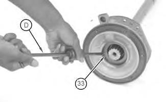
13. Install Tooling (C) and a suitable lifting device to bearing cage (29). The weight of bearing cage (29) and the input shaft is approximately 27 kg (60 lb). Remove bearing cage (29) and the input shaft as a unit. Illustration 13 g00318265 14. Remove bolt (30), washer (31), and flange (32) . Illustration 14 g01319763 15. Use Tooling (D) in order to remove seal (33) . 16. Remove the retainer ring that holds the bearing cage on the input shaft. Remove the bearing cage from the input shaft.
Remove the two retainer rings. There is a retainer ring on the top and the bottom of the cage. The retainer rings hold the bearing (36) in the cage.
Remove spacer (35) and bearing (36)


Illustration 15 g00318623 17. Remove seal rings (34) . Illustration 16 g00318856 18.
19.
.


Illustration 17 g00318304 20. Remove retaining ring (37) that holds bearing race (38) and gears (39) on the shaft. Illustration 18 g01319764 21. Use Tooling (E) to remove two gears (39) and race (38) . Illustration 19 g00318308 22. Remove the bearing cage from the shaft with a soft hammer.
Use Tooling (F) and remove the bearing inner race from the shaft.

Put an identification on each of the clutch housings. This should be done in order to identify the sequence and the location of the clutch housings. The housings must be installed in the same location. The housings must be installed in a reverse sequence. Do not mix the disc assemblies or the plate. Keep these parts with the respective clutch housing.

Illustration 20 g00318309 23. Remove ring (40). Remove bearing (41) . Illustration 21 g01319765 24.
Note:
recommended
bolts
housing.
No. 1 clutch piston in the No. 1

No. 1 clutch housing. The weight of the No. 1 clutch

Tooling (B)
the
a
kg (55 lb).
the No. 1 clutch housing and the No. 1 piston
Illustration 22 g00318386 Illustration 23 g01319766 Personal injury can result from being struck by parts propelled by a released spring force. Make sure to wear all necessary protective equipment. Follow the recommended procedure and use all
tooling to release the spring force. 25. Remove
(42). Install Tooling (G) in order to keep the
clutch
Remove remaining bolts (42) . 26. Install
and a suitable lifting device to the
housing and
piston is approximately 25
Remove
as
unit.


Illustration 24 g00318388 27. Turn the No. 1 clutch housing upside-down. Remove Tooling (G). Remove piston (43). Remove the ring seals from the piston and No. 1 clutch housing. Illustration 25 g00318389 28. Remove dowels (44) and springs (45) . Illustration 26 g01319767
Tooling (C)
suitable lifting device
No. 1 carrier (46). The weight of No. 1 carrier (46) is approximately 23 kg (50 lb). Remove No. 1 carrier (46) .
Note: Do not lose balls (47). When shafts (48) are removed, balls (47) can fall out of the shafts.
Remove shafts (48), gears (49) and washers (50) from No. 1 carrier. There is a washer on the top and the bottom of the gears. Remove the needle bearings from the gears.

Remove bolts (54), locks (51) and plates (53). Remove gear (52) from the No. 1 carrier.

29. Install
and a
to
Illustration 27 g00318626
30.
Illustration 28 g00318684 31.
Note: Do not lose balls (55). When shafts (56) are removed, balls (55) can fall out of the shafts.
Position the No. 1 carrier on the side. Remove shafts (56) and tubes (57) .
Remove gears (60) and washers (59) .

Remove needle bearings (58) .
Remove needle bearing (61) from No. 1 carrier.

Illustration 29 g00318686
32.
33.
34.
Illustration 30 g00318687 35.
2
2 clutch
No. 2 clutch.
The weight of the


Illustration 31 g00318398 36. Remove ring gear (62), clutch discs (63), plates (65), and plate (64) . Illustration 32 g01319769 37. Install Tooling (B) and a suitable lifting device in No.
housing.
No.
clutch is approximately 25 kg (55 lb). Remove the
Remove springs (66) . Illustration 33 g00318477
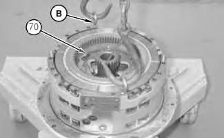

38. Remove ring gear (67), clutch discs (68) and plates (69) from the No. 2 clutch housing. Remove the piston from the housing. Remove the seal rings from the housing and the piston. Illustration 34 g01319770 Illustration 35 g01305069 39. Remove bolts (70) and remove the locks and the plates that hold the No. 3 clutch housing in position. 40. Install Tooling (B) and a suitable lifting device to the No. 3 clutch housing. The weight of the No. 3 clutch housing is approximately 25 kg (55 lb). Remove the No. 3 clutch housing. 41. Remove dowels (71) and springs (72) from the No. 4 and No. 5 clutch housings.


Illustration 36 g00318491 42. Remove ring gear (73), clutch discs (74), plate (75) and the piston from the clutch housing. Remove the seal rings from the piston and the clutch housing. Illustration 37 g01319771
43. Install Tooling (G) in order to keep the No. 4 and No. 5 clutch pistons in the clutch housing.
44. Install Tooling (B) and a suitable lifting device to No. 4 and No. 5 clutch housings. The weight of the No. 4 and No. 5 clutch housings is 29 kg (65 lb). Remove the clutch housing and the piston as a unit.
45. Remove springs (76), clutch discs (78), ring gear (71) and plate (79) .
46. Remove ring gear (80), clutch discs (81), and plate (82) from clutch housing (83) .

47. Turn clutch housing (83) upside-down. Remove Tooling (G). Remove the piston. Remove the ring seals from the piston and the housing.
48. Remove bolts (84) and the locks that hold No. 2 carrier (85) to the transfer gear case.

Illustration 38 g01319773
Illustration 39 g01323379
Illustration 40 g00318689
Install Tooling (C) and a suitable lifting device to the No. 2 carrier. The weight of the No. 2 carrier is approximately 23 kg (50 lb). Remove the No. 2 carrier.
Note: There is washer (92) on the top and the bottom of gear (93) .
Put the No. 2 carrier on the side. Pull shafts (89) out of the carrier. Remove gear (93) and washers (92). Remove needle bearings (90) from gear (91) .
Note: Use caution to prevent loss of balls (88) when shafts (89) are removed.
Remove shafts (89), gear (91) and the washers. Remove the needle bearings from gear (91) .


Note: Use caution to prevent the loss of the balls when shafts (86) are removed.
Remove shafts (86), gear (87) and the washers. Remove the needle bearings from the gear.
Note: There is a washer on the top and the bottom of the gear.
Illustration 41 g01319774 49.
Illustration 42 g01323384
50.
51.
52.


Illustration 43 g00318697 53. Remove cage (94), retainer ring (96) and output shaft (95) . Illustration 44 g00318698 54. Remove dowel (98) from the cage. Use Tooling (H) in order to remove dowel (98). Remove bearing (97) .
Transfer


Illustration 45 g00318699 Note: Use caution in order to prevent the loss of ball (102) when the cage is removed. 55. Remove cage (99) withTooling (J). Remove bearing (100) . 56. Inspect piston ring seals (101). If the seals are damaged or worn remove the seals and install new seals.
Gears Illustration 46 g01317165 1. Remove bolts (1) . Illustration 47 g01317167 2. Install two of bolts (1) in order to remove bearing cage (2) and the shims.


Illustration 48 g01319202 3. Remove ring (3). Use Tooling (K) to remove bearing (5). Remove the shims and bearing cup (4) from bearing cage (2) . Illustration 49 g01319204 4. Bend the locking tabs in order to remove bolts (6) . Illustration 50 g01319209


5. Install Tooling (L) in order to separate cover (7) from transfer case (8) . Illustration 51 g01319210 6. Attach Tooling (M) and a suitable lifting device to cover (7). The weight of cover (7) is approximately 39 kg (85 lb). Illustration 52 g01319211 7. Remove bolt (9) and washer (10) .


Illustration 53 g01319212 Illustration 54 g01319299 8. Use Tooling (N) in order to remove bearing assembly and race (11) and gear (12). Use Tooling (N) in order to remove bearing assembly and race (13) . Illustration 55 g01319214 9. Use Tooling (D) in order to remove plug (16). Install Tooling (P) in order to remove dowel (15). Remove bearing race (14) from cover (7) .


Illustration 56 g01319283 10. Remove ring (18). Remove gear assembly (17) . Illustration 57 g01319286 11. Use Tooling (Q) in order to remove bearing cone (19) and (20) (not shown) from the top and the bottom of gear assembly (18) .
Use Tooling (D) to remove plug (22). Install Tooling (P) in order to remove dowel (21). Remove cup (23) and bearing race (24)

Copyright 1993 - 2021 Caterpillar Inc.
All Rights Reserved.
Network For SIS Licensees.
May 11 10:34:29 UTC+0800 2021
Illustration 58 g01319374 Illustration 59 g01319288 12.
.
Private
Tue
Disassembly and Assembly
Transmission - Assemble
Procedure
1P-2420
1P-7407
1P-7405 Eyebolt
FT-0833 Clamp
Screw 6 - 40
1P-0510 Driver Gp
5B-4274
138-7573 Link Brackets
1P-0510 Driver Gp
9S-3263
FT-0834 Nozzle
Lock
1P-0520 Driver Gp
Cleanliness
an important
be thoroughly
not be used
Shutdown SIS Previous Screen Product: TRACK-TYPE TRACTOR Model: D7G TRACK-TYPE TRACTOR 7MB Configuration: D7G TRACK-TYPE TRACTOR 7MB00001-UP (MACHINE) POWERED BY 3306 ENGINE
D7G and D7G Series II Track-Type Tractors Power Train Media Number -KENR6354-02 Publication Date -01/09/2008 Date Updated -22/09/2008 i02627545
SMCS - 3030-016 Assembly
Table 1 Required Toolings Tool Part Number Part Description Qty A
Repair Stand 1 B
Eyebolt 3 C
3 G
2 H
1 K
1 L
Bolts 3 M
2 S
1 R
Thread
Compound 1 T
1 U
1 Note:
is
factor. Before assembly, all parts should
cleaned in cleaning fluid. Allow the parts to air dry. Wiping cloths or rags should
to dry parts
Lint may be deposited on the parts which may cause later trouble. Inspect all parts. If any parts are worn or damaged, use new parts for replacement. Transfer Gear Illustration 1 g01319374 Illustration 2 g01319288 1. Lower the temperature of bearing race (24) and bearing cup (23). Install bearing race (24) and bearing cup (23). Install dowel (21). Install plug (22) .

Illustration 3 g01319237 2. Install bearing cone (19) and (20) (not shown) onto gear assembly (18) . Illustration 4 g01319283 3. Install gear assembly (18). Install ring (17). Illustration 5 g01319214 4. Install bearing race (14) to cover (7). Install dowel (15). Install plug (16).
the temperature of bearing assembly and race (13) in order to install bearing assembly and race (13). Place the cover over the pinion. Install gear (12). Raise the temperature of bearing assembly and race (11) in order to install bearing assembly and race (11)

Apply Tooling (R) on bolt (9). Install washer (10) and bolt (9). Tighten bolt (9) to a torque of 108 ± 7 N·m (80 ± 5 lb ft).

Illustration 6 g01319934 Illustration 7 g01320019 5. Raise
. 6.

Thank you very much for your reading. Please Click Here. Then Get COMPLETE MANUAL.NOWAITING NOTE: If there is no response to click on the link above, please download the PDF document first and then clickonit. GET MORE OTHER MANUALS https://www.aservicemanualpdf.com/ GET MORE OTHER MANUALS https://www.aservicemanualpdf.com/

Illustration 8 g01319210 Illustration 9 g01319204 7. Attach Tooling (M) and a suitable lifting device to cover (7). The weight of cover (7) is approximately 39 kg (85 lb). Install bolts (3) and bend the locking tabs. Illustration 10 g01319202
8. Lower the temperature of bearing (5) in order to install bearing outer race (4) into bearing cage (2). Use Tooling (U) to install bearing (5). Install ring (4). Install bearing cage (2) without the shims. Install two bolts (1). Tighten bolts (1) to a torque of 1.7 N·m (15 lb in).
9. Turn the pinion for at least three revolutions in order to seat the bearings.
10. Tighten bolts (1) again. Tighten bolts (1) to a torque of 3.4 N·m (30 lb in).
11. Turn the pinion for at least three revolutions in order to seat the bearings.

12. Tighten bolts (1) again. Tighten bolts (1) to a torque of 3.4 N·m (30 lb in).
13. Measure the gap between the case and bearing cage (2) at bolts (1). Average the two measurements from Step 12. Add 0.23 mm (0.009 inch) to the average. This result is the required thickness of the shims.
Install the shims
Illustration 11 g01319996
Illustration 12 g01317165 14.
and bearing cage (2). Install remaining bolts (1) . Transmission
Turn the transfer gear case
plate (9)
Lower the temperature of bearing (10). Install bearing (16) in cage (11)
Install piston ring seals (12). If the seals are damaged or worn, replace the seals with new seals. Put clean grease on the seals.
Do not damage piston ring seals (12) when the cage is installed.
Position ball (13) and install cage (11)
5. Lower temperature of the bearing. Install the bearing in cage (14) by using Tooling (K). Make sure that the hole in the bearing is in alignment with the hole in the cage. Install the dowel and the plug that holds the bearing in the cage.

Position output shaft (15) in the transfer gear case. Install retainer ring (16) and bearing cage (17)

Illustration 13 g01307712 1.
upside-down and install
. 2.
. 3.
Note:
4.
. Illustration 14 g01320333
Illustration 15 g00320329 6.
.