
S7-UNAE12A 3/3
This workshop manual has been prepared to provide information regarding repair procedures on Hino Trucks.
FOREWORD
Chassis Workshop ManualS1-UNAE12A 2/2 J08E-VB, VC Engine Workshop ManualS5-UJ08E12A
S7-UNAE12A 1/3
S7-UNAE12A 2/3
Please note that the publications below have also been prepared as relevant workshop manuals for the components and systems in these vehicles.
Manual NamePub. No.
Applicable for HINO 238, 258LP, 268, 338, 358 series, equipped with J08E-VB and J08E-VC engine
MENU
When making any repairs on your vehicle, be careful not to be injured through improper procedures. As for maintenance items, refer to the Driver’s / Owner’s Manual. All information and specifications in this manual are based upon the latest product information available at the time of printing. Hino Motors Sales U.S.A., Inc. reserves the right to make changes at any time without prior notice.
Trouble Shooting Workshop Manual
MODELSHINO 238, 258LP, 268, 338, 358
Production Model Code NE8J, NF8J, NJ8J, NV8J, NH8J
BRAKE EQUIPMENT BR01-001 BR01-002
GENERAL INTRODUCTIONGN02-001
SERVICE BRAKE BR02-001 BR02-002
CHAPTER MANUAL NO.S1-UNAE12A 1/2 (U.S.A.), S1-CNAE12A 1/2 (CANADA)
CHAPTER REFERENCES REGARDING THIS WORKSHOP MANUAL
CLUTCH MAIN UNITCL02-001CL02-002 CLUTCH
AUTOMATICTRANSMISSIONCONTROLCL03-001MAINUNITTR02-001TRANSMISSIONTR04-001 TR04-002
EXHAUST BRAKEBR05-001
ThisELECTRICELECTRICALCABCHASSISSUSPENSIONWHEELREARFRONTPOWERSTEERINGSTEERINGBRAKEBR07-001EQUIPMENTSR01-001UNITSR02-001STEERINGSR03-001AXLEAX02-001AXLEAX03-001&TIREAX04-001SU02-001FRAMEFC02-001CA02-001EQUIPMENTEL01-001WIREEL02-001manualdoesnotcontainitemsonhalf-tonedotmeshing.
TRANSMISSION/TRANSFER CONTROL TR06-001 TR06-002
PARKING
Use this chart to the appropriate chapter numbers for servicing your particular vehicle.
PROPELLER SHAFT PP02-001 DIFFERENTIAL CARRIER DF02-001
ABS (ANTI-LOCK BRAKE SYSTEM)BR03-001BR03-002
MANUALWORKSHOP
CLUTCH EQUIPMENT CLUTCH MAIN UNIT CLUTCH INDEX:DIFFERENTIALDIFFERENTIALPROPELLERTRANSMISSIONPTOAUTOMATICTRANSFERTRANSMISSIONTRANSMISSIONCONTROLEQUIPMENTMAINUNITMAINUNITTRANSMISSION(POWERTAKE-OFF)/TRANSFERCONTROLSHAFTEQUIPMENTCARRIERCHASSISGROUP1/4PROPELLERSHAFTEQUIPMENTBRAKEEQUIPMENTSERVICEBRAKEABSGENERALINTRODUCTION
ES START (EASY & SMOOTH START) SYSTEM EXHAUST INDEX:STEERINGSTEERINGPARKINGRETARDERBRAKEBRAKEBRAKEEQUIPMENTUNITCHASSISGROUP2/4POWERSTEERINGAXLEEQUIPMENTFRONTAXLEREARAXLEWHEEL&TIRESUSPENSIONEQUIPMENTSUSPENSIONCHASSISEQUIPMENTCHASSISFRAMECOUPLER(5THWHEEL)PINTLEHOOK
CAB EQUIPMENTINDEX:CABCHASSIS
ELECTRIC WIRE
HYBRID SYSTEM
GROUP 3/4
ELECTRICAL EQUIPMENT
FUEL
ENGINE CONTROL
INDEX:OTHERSCABSUSPENSIONBRAKECONTROLCONTROLCONTROLEQUIPMENTCONTROLCHASSISGROUP4/4
GN02-001 GENERAL INTRODUCTION.....................GN02-2 GENERAL GLOSSARY...................................................GN02-36SYMPTOMINFORMATIONANDVEHICLERECOMMENDEDFORSPECIFIEDFORSPECIFIEDMETRICNYLONFORSEALANTPRECAUTIONS.............................................GN02-15THISHOWIDENTIFICATIONPRECAUTIONS.............................GN02-2INFORMATION...................GN02-5TOUSEWORKSHOPMANUAL.........................GN02-12ONTHETAPEREDSCREWPIPING..................................................GN02-18TUBEREPLACEMENTMETHOD...GN02-19INFORMATION...............................GN02-21TORQUESTANDARDBOLTSANDNUTS...........GN02-23TORQUEFLANGEBOLTSANDNUTS................GN02-23LUBRICANTS..................GN02-25LIFTSUPPORTLOCATIONS........................GN02-27DISPLAY..............................GN02-29SIMULATION..............................GN02-34GLOSSARYOFSAEANDHINOTERMS.....GN02-39
GENERAL INTRODUCTION (CHASSIS)
GENERAL INTRODUCTION (CHASSIS) GN02–1
• Remove rings, watches, ties, loose hanging jewelry and loose clothing before starting work on the vehicle.
• Be careful not to leave any tool in the engine compartment. The tool may be hit by moving parts, which can cause personal injury.Indicates
WARNING
GENERAL INTRODUCTION
Indicates a potential hazardous situation if proper procedures are not followed and could result in death or serious injury.
When working on your vehicle, observe the following general precautions to prevent death, personal injury and/or property damage in addition to the particular DANGERS, WARNINGS, CAUTIONS and NOTICES in each chapter.
• Always wear safety glasses or goggles to protect your eyes.
• If it is necessary to run the engine after the hood is raised (tilted), make sure that the parking brake is firmly applied, the wheels are blocked, and the gear shift lever is positioned in "Neutral" before staring the engine.
• Read carefully and observe the instructions specified on the jack before using it.
• Run the engine only in a well-ventilated area to avoid inhalation of carbon monoxide.
• Use safety stands to support the vehicle whenever you need to work under it. It is dangerous to work under a vehicle supported only by a jack.
• Be careful not to damage lines and hoses by stepping or holding your feet on them.
Some recommended and standard maintenance services for your vehicle are included in this section. When performing maintenance on your vehicle be careful not to get injured by improper work. Improper or incomplete work can cause a malfunction of the vehicle which may result in personal injury and/or property damage. If you have any question about performing maintenance, please consult your Hino dealer.
• Large electric current flows through the battery cable and starter cable. Be careful not to cause a short which can result in personal injury and/or property damage.
• Keep yourself, your clothing and your tools away from moving parts such as the cooling fan and V-belts when the engine is running.
GENERAL PRECAUTIONS
an extremely hazardous situation if proper procedures are not followed and could result in death or serious injury.
• Do not smoke while working on the vehicle since fuel, and gas from battery are flammable.
• To avoid serious burns, keep yourself away from hot metal parts such as the engine, exhaust manifold, radiator, muffler, exhaust pipe and tail pipe.
Indicates the need to follow proper procedures and to pay attention to precautions so that efficient service is provided.
DEFINITION OF SAFETY TERMS
Indicates a hazardous situation if proper procedures are not followed and could result in serious injury or damage to parts/equipment.
Provides additional information to help you to perform the repair efficiently.
• Always turn off the starter switch to stop the engine, unless the operation requires the engine running. Removing the key from the switch is recommended.
GENERAL INTRODUCTION (CHASSIS)GN02–2
EN00Z08020100001
• Take utmost care when working on the battery. It contains corrosive sulfuric acid.
• When working on the vehicle, apply the parking brake firmly, place the gear shift lever in "Neutral" or "N" and block the wheels.
• Bind long hair securely behind the head.
GENERAL INTRODUCTION (CHASSIS) GN02–3
(6)Make sure that the engine of the towed vehicle is kept running. If the engine is off, no compressed air/ no vacuum will be available for the brake. This is dangerous, as the brake system does not function if the engine is not running. In addition, the power steering system will not function. The steering wheel, therefore, will become unusually hard to turn, making it impossible to control the vehicle.
When towing from the front end with the front wheels raised off the ground, remove the rear axle shafts to protect the transmission and differential gears from being damaged. The hub openings should be covered to prevent the loss of axle lubricant or the entry of dirt or foreign matter. The above-mentioned precautions should be observed for vehicles equipped with either manual or automatic transmission, and for even short distance towing. After being towed, check and refill the rear axle housing with lubricant if necessary.
1.Towing procedures
(4)Keep the gear shift lever in Neutral.
(7)Note that the engine brake and exhaust brake cannot be applied, if the propeller shaft is removed.
(2)Rear end towing
When being towed with the rear wheels raised off the ground, fasten and secure the steering wheel in a straight-ahead position.
(1)When rebuilding an engine, portions of an engine, or an engine system, there must be a reasonable technical basis for knowing that the resultant engine is equivalent, from an emissions standpoint, to a certified configuration (i.e., tolerances, calibrations, specifications) and the model year(s) of the resulting engine configuration must be identified. A reasonable basis would exist if:
a.Parts installed, whether the parts are new, used, or rebuilt, are such that a person familiar with the design and function of motor vehicle engines would reasonably believe that the parts perform the same function with respect to emissions control as the original parts; and
1.Heavy-dutyACTengine
rebuilding practices.
When being towed, always place the gear shift lever in "Neutral" and release the parking brake completely. In order to protect the bumper, fit a protection bar against the lower edge of the bumper and put a wood block under the frame near the No. 1 cross member when attaching the towing chain. Never lift or tow the vehicle if the chain is in direct contact with the bumper.
(1)Make sure that the propeller shaft of the vehicle to be towed is removed. When the differential gear or rear axle shaft is defective, remove both right and left rear axle shafts, then cover the hub opening to prevent loss of axle lubricant and entry of dirt or foreign matter.
(8)Make a slow start to minimize shock. Towing speed should be less than 30 km/h {18 mile/h}.
(1)Front end towing (with front wheels raised off the ground)
(3)The angle of pulling direction of the cable fastened to the towing hook must not exceed 15 in horizontal and vertical directions from the straight ahead, level direction. Avoid using the hook in a way that subjects it to jerk, as in towing a vehicle trapped in a gutter.
§ 86.004-40
• The provisions of this section are applicable to heavy-duty engines subject to model year 2004 or later standards and are applicable to the process of engine rebuilding (or rebuilding a portion of an engine or engine system). The process of engine rebuilding generally includes disassembly, replacement of multiple parts due to wear, and reassembly, and also may include the removal of the engine from the vehicle and other acts associated with rebuilding an engine. Any deviation from the provisions contained in this section is a prohibited act under section 203(a) (3) of the Clean Air Act (42 U.S.C. 7522(a) (3)).
•TOWING
b.Any parameter adjustment or design element change is made only:
In accordance with the original engine manufacturer's instructions; or
(5)Make sure that the starter switch is kept in the "ON" position, if the engine is not running.
(2)Use a heavy duty cable or rope when towing the vehicle. Fasten the cable securely to the towing hook on the frame.
2.If the engine of the towed vehicle is defective, make sure that the vehicle is towed only by a tow truck designed for that purpose.
Where data or other reasonable technical basis exists that such parameter adjustment or design element change, when performed on the engine or similar engines, is not expected to adversely affect in-use emissions.
CLEAN AIR
(2)When an engine is being rebuilt and remains installed or is reinstalled in the same vehicle, it must be rebuilt to a configu ration of the same or later model year as the original engine. When an engine is being replaced, the replacement engine must be an engine of (or rebuilt to) a configuration of the same or later model year as the original engine.
GENERAL INTRODUCTION (CHASSIS)(3)AtGN02–4time
d.Records must be kept for a minimum of two years after the engine is rebuilt.
(5)Records shall be kept by parties conducting activities included in paragraphs (1) through (4) of this section. The records shall include at minimum the mileage and/or hours at time of rebuild, a listing of work performed on the engine and emissions-related control components including a listing of parts and components used, engine parameter adjustments, emissions-related codes or signals responded to and reset, and work performed under paragraph (4) of this section.
2.Maintenance instructions.
a.Parties may keep records in whatever format or system they choose as long as the records are understandable to an EPA enforcement officer or can be otherwise provided to an EPA enforcement officer in an understandable format when b.Partiesrequested.arenotrequired to keep records of information that is not reasonably available through normal business practices including information on activities not conducted by themselves or information that they cannot reasonably
(4)When conducting a rebuild without removing the engine from the vehicle, or during the installation of a rebuilt engine, all critical emissions-related components listed in § 86.004-25(2) not otherwise addressed by paragraphs (1) through (3) of this section must be checked and cleaned, adjusted, repaired, or replaced as necessary, following manufacturer recommended practices.
of rebuild, emissions-related codes or signals from on-board monitoring systems may not be erased or reset without diagnosing and responding appropriately to the diagnostic codes, regardless of whether the systems are installed to satisfy requirements in § 86.004-25 or for other reasons and regardless of form or interface. Diagnostic systems must be free of all such codes when the rebuilt engine is returned to service. Such signals may not be rendered inoperative during the rebuilding process.
§ 86.010-38
(1)For each new diesel-fueled engine subject to the standards prescribed in § 86.007-11, as applicable, the manufacturer shall furnish or cause to be furnished to the ultimate purchaser a statement that "This engine must be operated only with ultra low-sulfur diesel fuel (meeting EPA specifications for highway diesel fuel, including a 15 ppm sulfur cap)."
c.Partiesaccess. may keep records of their rebuilding practices for an engine family rather than on each individual engine rebuilt in cases where those rebuild practices are followed routinely.
GENERAL INTRODUCTION (CHASSIS) GN02–5
• VEHICLE IDENTIFICATION NUMBER (VIN) is comprised of 17 digits and letters. The VIN label is affixed to the left pillar of the Thesecab.numbers are used for identification purposes when you have a vehicle registered or inspected. Please quote these numbers when ordering spare parts or reporting technical matter to receive prompt service attention.
• The following is an explanation of the items that are listed on the VIN label.VINlabel
IDENTIFICATION INFORMATION
EN00Z08020200001
1.VEHICLE IDENTIFICATION NUMBER
-2500RDS3.511.901.441.000.740.645.09 RS19-145RS17-145
2500RDS3.511.901.441.000.740.645.09 RS19-145RS17-145
2200RDS3.101.811.411.000.710.614.49 RS19-145RS17-145
PBD-2500RDS3.511.901.441.000.740.645.09 RS19-145RS17-145
MODELSERIES
2200HS3.101.811.411.000.710.614.49 RS17-145 HD orLA RS19-145
VEHICLE IDENTIFICATION NUMBER (VIN) STRUCTURE on the following page. (2)P.S. (PRODUCTION SERIES) AND VEHICLE COMPONENTS
(1)VINGN02–6See
TRANSMISSION RATIOREARAXLESERIES
HINO238(6)
BRAKESER-VICE BRAKEPARK-ING SUSPEN-SION
GENERAL INTRODUCTION (CHASSIS)
-2200HS3.101.811.411.000.710.614.49 RS17-145 FW orLA RS19-145
-2200RDS3.101.811.411.000.710.614.49 RS19-145RS17-145
-2200RDS3.101.811.411.000.710.614.49 RS19-145RS17-145
NE8J
(CLASS)MODEL
HINO258(6)
-2500RDS3.511.901.441.000.740.645.09 RS19-145RS17-145
JBD350mmFS54069.015.273.222.041.361.008.63 RS17-145 FWA RS19-145
HBD
-2200HS3.101.811.411.000.710.614.49 RS19-145RS17-145
NJ8J
TIONPRODUC-CODE CLUTCHSIZE TRANS-MIS-SIONSERIES
1st2nd3rd4th5th6thRev.
NE8JHBD-
GBD350mmFS54069.015.273.222.041.361.008.63 RS17-145 HD orLA RS19-145
KBD
NE8J
HBD
FW orLAKBD
-2500RDS3.511.901.441.000.740.645.09 RS19-145RS17-145
JBD350mmFS54069.015.273.222.041.361.008.63RS19-145
PBD-2500RDS3.511.901.441.000.740.645.09 RS19-145RS17-145
NBD350mmFS64069.015.273.222.041.361.008.63 RS21-145 FW orLA RS23-160
-3500RDS4.592.251.541.000.750.655.00 RS23-160RS21-145
-2200HS3.101.811.411.000.710.614.49 RS19-145RS17-145
HINO268(7)
NV8J
-3000RDS3.491.861.411.000.750.655.03 RS23-160RS21-145
HINO268(6)
-2500RDS3.511.901.441.000.740.645.09 RS19-145RS17-145
-3500RDS4.592.251.541.000.750.655.00 RS23-160RS21-145
TRANSMISSION RATIOREARAXLESERIES BRAKEPARK-ING SUSPEN-SION
-3000RDS3.491.861.411.000.750.655.03 RS23-160RS21-145
BRAKESER-VICE
SBD
-2200HS3.101.811.411.000.710.614.49 RS19-145RS17-145
GBD350mmFS54069.015.273.222.041.361.008.63 RS17-145 HD orLA RS19-145
-2500RDS3.511.901.441.000.740.645.09 RS23-160RS21-145
-2200RDS3.101.811.411.000.710.614.49 RS19-145RS17-145
-2500RDS3.511.901.441.000.740.645.09 RS23-160RS21-145
(CLASS)MODEL
-2200RDS3.101.811.411.000.710.614.49 RS19-145RS17-145
GENERAL INTRODUCTION (CHASSIS) GN02–7
PBD
MODELSERIES 1st2nd3rd4th5th6thRev.
TBD350mmFS64069.015.273.222.041.361.008.63 RS23-160RS21-145
TIONPRODUC-CODE CLUTCHSIZE TRANS-MIS-SIONSERIES
NJ8J
TBD350mmFS64069.015.273.222.041.361.008.63RS23-160
NF8J
-3500RDS4.592.251.541.000.750.655.00 RS23-160RS21-145
-3000RDS3.491.861.411.000.750.655.03 RS23-160RS21-145 -3500RDS4.592.251.541.000.750.655.00 RS23-160RS21-145
BRAKE CONTROL CODE D: ACTING ON DIFFERENTIAL W: ACTING ON REAR WHEEL A:L:SUSPENSIONLEAFAIR (CLASS)MODEL TIONPRODUC-CODE CLUTCHSIZE TRANS-MIS-SIONSERIES TRANSMISSION RATIOREARAXLESERIES BRAKESER-VICE BRAKEPARK-ING SUSPEN-SION MODELSERIES 1st2nd3rd4th5th6thRev.
GENERAL INTRODUCTION (CHASSIS)GN02–8HINO338(7)
PBD
NBD350mmFS64069.015.273.222.041.361.008.63 RS21-145 FW RS23-160
TBD350mmFS64069.015.273.222.041.361.008.63 RS23-160RS21-145
CODESERVICE BRAKE H: Hydraulic F: Full air
EBD-2500RDS3.511.901.441.000.740.645.09RS21-145
-2500RDS3.511.901.441.000.740.645.09 RS21-145 FW orLA RS23-160
SBD -2500RDS3.511.901.441.000.740.645.09 RS23-160RS21-145
FW orLASBD -3500RDS4.592.251.541.000.750.655.00RS23-160-3000RDS3.491.861.411.000.750.655.03RS23-160
-3000RDS3.491.861.411.000.750.655.03 RS23-160RS21-145
HINO358(8)
PARKING
DBD350mmFS64069.015.273.222.041.361.008.63RS21-145 HD orLA
NV8J
NH8J
VEHICLEINCOMPLETEVEHICLEINCOMPLETEVEHICLEINCOMPLETE VEHICLEINCOMPLETElessorkg17931-kg.10434NJ[23,001-26,000(lbs.)](CLASS6) lessorkg14968-kg.13609 7)(CLASS(lbs.)]33,000-[30,001lessorkg14968-kg.13609 7)(CLASS(lbs.)]33,000-[30,001 lessorkg15875-kg14969 8)(CLASS](lbs.)35,000-[33,001 NE HINO HINO HINONHHINOlessorkg11793-kg.8846HINO[19,501-26,000(lbs.)](CLASS6)HYDRAULIC AIRFULL
GENERAL INTRODUCTION (CHASSIS) GN02–9 (2016MY)CANADAandU.S.A.FORSTRUCTURE(VIN)NUMBERIDENTIFICATIONVEHICLEHINO WMIVDSCDVIS123456789101112131415165PVNJ8JT2G4S1000171MANUFACTURER TYPE MAKE, MODELLINE & CAB/BODY TYPE,SERIES, BRAKE MODELSYSTEM ASSEMBLYYEAR PLANT ENGINE MODELWHEEL CHECKBASE DIGITMODIFICATION SEQUENTIAL NUMBER CODE JHA JHB TRUCK VEHICLEINCOMPLETEMANUFACTURERTYPE LTD.MOTORS,HINO LTD.MOTORS,HINO VEHICLE5PVINCOMPLETEMOTORSHINO MANUFACTURING INC.U.S.A., MOTORSHINOVEHICLE2AYINCOMPLETECANADA,LTD. CODE PCODE 2024YEARYEAR R2025 S2026 L2021T2027M2022 N2023 I2018 J2019 K2020G2016 H2017 CODE 8J J08E-VCMODEL 220HPDIESELLITERS,7.6 260HPDIESELLITERS,J08E-VB7.6MANUFACTURERDESCRIPTION LTD.MOTORS,HINO CODE G3,861LENGTH NV-NE mmin. 4,445J L4,750 5,207M N5,385 P5,512 R5,969 6,426T 6,883V 152 175 187 205 212 217 235 253 271 CODE S DESCRIPTION LETTERNEWA ALLOTTEDBETWILL MAJOREVERYUAT MODIFICATION Z CODE 1 PLANTASSEMBLY LTD.MOTORS,HINO JAPANINPLANTHINO Plant3Canada MODELPlant4W.VMAKECODE NFHYDRAULICTYPECAB/BODY&LINE VEHICLEINCOMPLETE ClassVehicleandGVWRIntended Classand BRAKE SYSTEMS NV AIRFULLAIRFULL
SAPH00Z080200007
For all models
5.CLEAN IDLE CERTIFIED LABEL FOR U.S.

CARB § 1956.8. Exhaust Emission Standard and Test Procedure (a) (b) Heavy-Duty Diesel Engine Idling Requirements
GENERAL INTRODUCTION (CHASSIS)GN02–10
VEHICLE NOISE EMISSION CONTROL INFORMATION THIS VEHICLE CONFORMS TO U.S. EPA REGULATIONS FOR NOISE EMISSION APPLICABLE TO MEDIUM AND HEAVY TRUCKS. THE FOLLOWING ACTS OR THE CAUSING THEREOF BY ANY PERSON ARE PROHIBITED BY THE NOISE CONTROL ACT OF 1972. (A)THE REMOVAL OR RENDERING INOPERATIVE. OTHER THAN FOR PURPOSES OF MAINTENANCE, REPAIR, OR REPLACEMENT, OF ANY NOISE CONTROL DEVICE OR ELEMENT OF DESIGN (LISTED IN THE OWNER' S MANUAL) INCORPORATED INTO THIS VEHICLE IN COMPLIANCE WITH THE NOISE CONTROL ACT. (B)THE USE OF THIS VEHICLE AFTER SUCH DEVICE OR ELEMENT OF DESIGN HAS BEEN REMOVED OR RENDERED INOPERATIVE. MFD BY:HINO MOTORS, LTD. DATE OF MANUFACTURE 03/2009
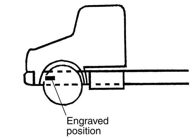
• Chassis serial number is engraved on the left side frame near the front wheel.
SAPH00Z080200011SAPH00Z080200010SAPH00Z080200009SAPH00Z080200008
• Make sure that the following clean engine idling certified label is affixed to the outside of the left door. By the CARB below, the label must be affixed there to prove that the new vehicle with diesel engine manufactured from Jan., 2008 conforms to this low.
4.CHASSIS SERIAL NUMBER
• The Vehicle Noise Emission Control Information is affixed to the side of the left door. The name of manufacturer, production year and month, and noise emission applicable to medium and heavy trucks in conformity with U.S. EPA Regulations are displayed.
2.VEHICLE NOISE EMISSION CONTROL INFORMATION
3.ENGINE SERIAL NUMBERS.
• Please quote these numbers when ordering spare parts or reporting technical matter to receive prompt service attention. The engine serial number is engraved on the engine cylinder block.
6.VEHICLE EMISSION CONTROL INFORMATION
SAPH00Z080200013
• The Vehicle Emission Control Information is affixed to the side of the left door. The name of manufacturer, production year and month, and emission applicable to medium and heavy trucks in conformity with U.S. EPA Regulations are displayed. example
GENERAL INTRODUCTION (CHASSIS) GN02–11
VehiclelabelVIN emission control SAPH00Z080200012information For
GENERAL INTRODUCTION (CHASSIS)GN02–12
SPECIAL TOOL is dealt with in each chapter. When ordering a special tool, confirm the part number with the applicable parts catalog.
Repair procedures when self-explanatory, such as simple installation and removal of parts, have been omitted. Illustrations, such as the one below, have been provided to make such simple procedures clear. Only essential procedures requiring specific directions have been dealt with explicitly.
This workshop manual is designed as a guide for servicing the vehicle. An INDEX is provided on the first page of each chapter.
• RERAIR PROCEDURES
HOW TO USE THIS WORKSHOP
MANUALEN00Z08020200002
TROUBLESHOOTING is dealt with in each chapter. When beginning operations, refer to the TROUBLESHOOTING section for a guide to appropriate diagnosis.
Tightening torque Unit: N m {kgf cm, lbf ft}
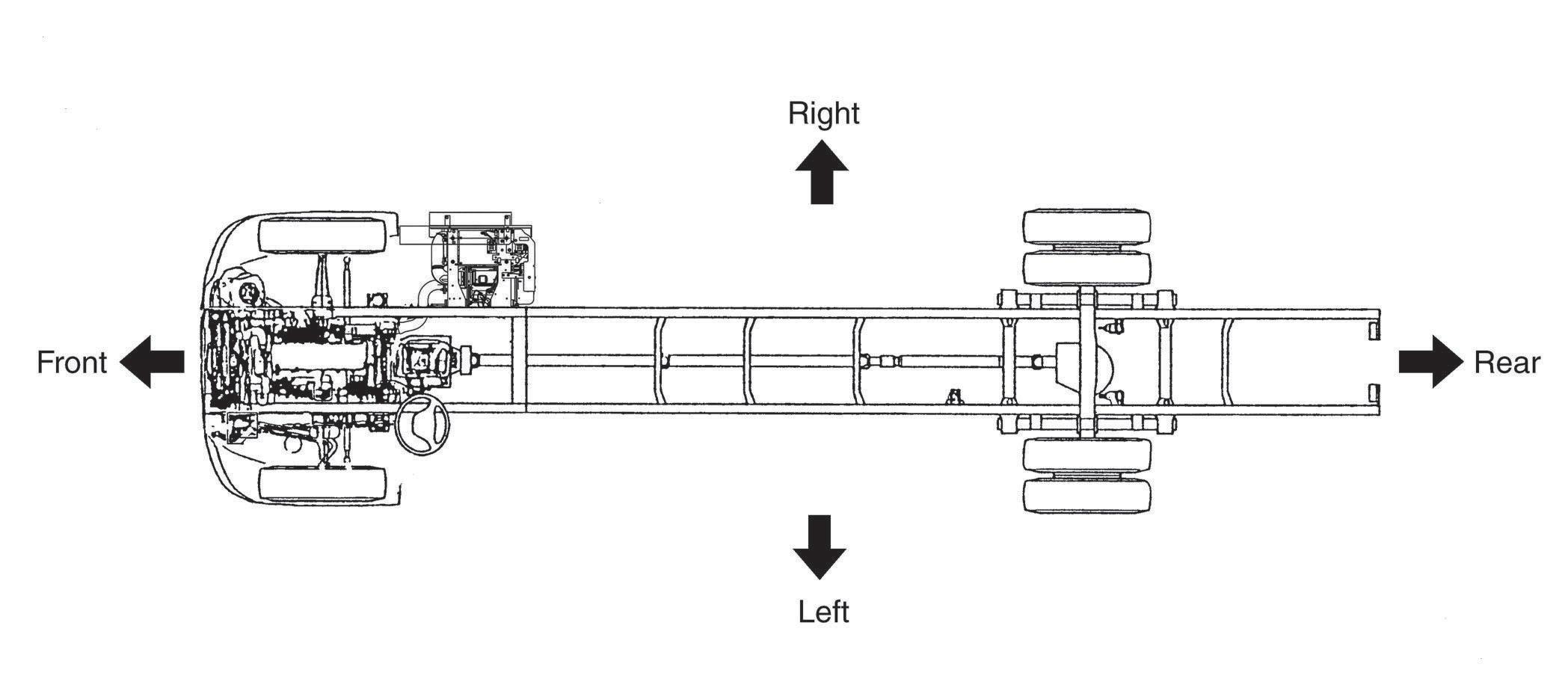
Definition of vehicle right and left. Right and left refers to the left and right sides of the vehicle as seen while looking down the center line from the rear towards the
SAPH00Z080200014front.1Clevis8Return spring 2Lock nut9Body 3Push rod10Hose A2.5-4.47Piston6Thrust5Retainer4Boot11O-ringjointring12Softwasherwasher13Bolt{25-45,1.8-3.2}
GENERAL INTRODUCTION (CHASSIS) GN02–13
In some cases, illustrations may be of parts which differ in some nonessential way from the parts found on your particular vehicle. In such cases, the principle or procedure being illustrated applies regardless of such nonessential differences.
MAIN CYLINDER EXAMPLE:
• DEFINITION OF TERMS
GENERAL INTRODUCTION (CHASSIS)GN02–14 SAPH00Z080200015
EN00Z0802C100001
(4)Do not remove the harness connector, electric component box, and cover except for repair and inspection.
(1)Perform marking on a clamp and a clip and secure then in original position so that the wire harness will not interfere with the end and acute angle section of the body and a bolt.
• Be sure to wait for at least ten minutes after the starter key is turned to "LOCK" position before you disconnect the battery terminals from the battery, as the vehicle data is recorded on ECU and DCU starts working for the exhaust gas after treatment after the starter key is turned to "LOCK" position. Otherwise, the vehicle data will not be recorded on ECU properly and DCU will not complete working properly, which may result in the malfunction of DPR system and DEF-SCR system.
(1)Before electrical system work, remove the cable from the minus terminal of the battery in order to avoid burning caused by short-circuiting.
PRECAUTIONS PRECAUTIONS FOR ELECTRICAL SYSTEM
2.HANDLING OF ELECTRONIC PARTS
(1)Never give an impact to electronic parts of a computer or relay.
GENERAL INTRODUCTION (CHASSIS) GN02–15
• The MIL (malfunction indicator light) may come on when the starter key is turned to "ON" position again, even if you wait for at least ten minutes before disconnecting the battery terminals from the battery after the starter key is turned to "LOCK" position. In this case, use HINO DX to clear the DTC (P204F and P068A), to turn off the MIL and to conduct DPR regeneration manually.
(2)Keep electronic parts away from high temperatures and humidity. (3)Never splash water onto electronic parts in washing the vehicle.
In restoration, make sure there is no attachment or entry of water and foreign matters and mount them properly, because it causes degradation of waterproof function.
SAPH00Z080200016Loosen Incorrect SAPH00Z080200017 Incorrect Incorrect IncorrectSAPH00Z080200018
If removal is necessary, pay attention that water and foreign matters do not attach or enter to the connector, terminals, electric component box, and cover.
1.REMOVING THE BATTERY CABLE !WARNING
(2)To attach a part, take care not to bite the wire harness.
(2)To remove the battery cable, fully release the nut to avoid damage to the battery terminal. Never twist the terminal.
3.HANDLING OF WIRE HARNESS
GENERAL INTRODUCTION (CHASSIS)GN02–16
(1)To remove a connector with lock, release the lock then pull it out. (2)To remove a connector, hold the connector (indicated by an arrow in the figure) to pull it out. Never pull the harness.
Incorrect Incorrect Correct SAPH00Z080200019
!WARNING
(4)To insert a test lead into the connector, insert it from behind the con(5)Innector.case
• Be sure to read and follow the procedures and instructions on the service bulletin before the installation of the battery disconnect
BATTERY DISCONNECT SWITCH
6.HANDLINGswitch.OF
4.HANDLING OF CONNECTOR
(3)To connect a connector with lock, insert it until it clicks.
it is difficult to insert a test lead from behind the connector, prepare a harness for inspection and perform inspection.
• Wait for at least one minute before using the battery disconnect switch after the starter key is turned to "LOCK" position. Otherwise, the vehicle data will not be recorded on ECU properly, which may result in the malfunction of DPR system.
!WARNING
• Installation of the battery disconnect switch on the power supply circuit for the dosing control unit of DEF-SCR (DCU) may damage or result in the malfunction of DEF-SCR system.
5.INSTALLATION OF BATTERY DISCONNECT SWITCH
a.Turn the starter switch off. b.Disconnect the negative terminal of the battery. c.Earth welding equipment securely, near to the area to be welded.
Alternatoretc.ARCmachinewelding SAPH00Z080200020
(2)In order to prevent damage to ancillary equipment components from sparks during welding, take steps such as putting fire-resistant covers over things like the engine, meters, steering wheel, hoses, tubes, leaf spring and tires.
(1)Disconnect the earth terminal of the battery at the frame fitment and earth the welding equipment securely to the frame itself. (Do not fit the welding equipment earth to such things as the tire rims, brake pipes or fuel pipes and leaf spring, etc.)
GENERAL INTRODUCTION (CHASSIS) GN02–17
ComputerBatteryChassis frameChassis frame
PRECAUTIONS FOR ELECTRIC WELDING
d.Put back battery negative ground as original condition. e.Finally check the functioning of all instruments.
Disconnect the ground terminal for battery at the connecting point on the frame and disconnect the ground for computer as well.
Electrical components such as the alternator and tachograph are directly connected to the battery and one end is earthed to the chassis frame. Under these conditions, welding current will flow back along the earth circuit if electric welding is carried out and damage may be caused to the alternator, tachograph, electrical components, etc. Consequently, the following precautions are always to be taken during welding.
Connect the ground of the ARC welding machine near the place on the frame to be welded but not connect it to plated parts such as fuel pipes, brake pipes and leaf spring.
1.PRECAUTION FOR ELECTRIC WELDING
Thank you very much for your reading. Please Click Here. Then Get COMPLETE IfNOTE:MANUAL.NOWAITINGthereisnoresponse to click on the link above, please download the PDF document first and then clickonit.

SEALANT ON THE TAPERED SCREW FOR PIPING
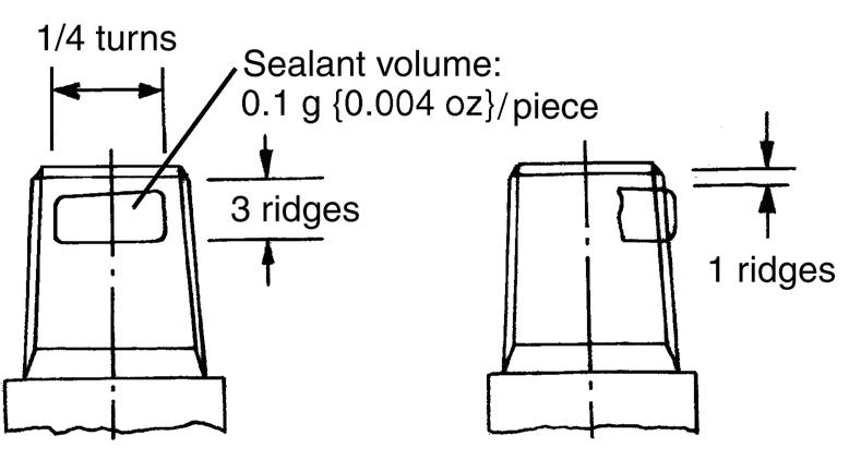
(1)To apply sealant (LOCTITE #575), use waste and thinner to wipe the dirt off the sealing section, directly apply the sealant by a quarter turn (three ridges) starting from the second ridge from the tip, then assemble in accordance with the tightening torque table below. Wipe dirt off the mating part (female screw) before tightening it.
Aluminum, brass 25 5 {250 50, 18.1 3.6} 34 5 {350 50, 25.3 3.6} 44 5 {450 50, 32.5 3.6}
2.ATTACHING
1.REMOVAL
Screw diameter
1/81/43/81/2
(1)The sealant (LOCTITE #575) has a high sealing capability. The return torque of taper joint is about 1.5 times as high as the initial tightening torque. To remove the joint, use a longer wrench.
In!WARNINGcasethesealant has entered your eye or attached to your skin, wash it away in running water.
(2)To replace vulcanized tape with sealant, remove the tape beforehand, same as (1).
MaterialSteel 20 5 {200 50, 14.4 3.6} 49 10 {500 100, 36.2 7.2} 64 15 {650 150, 47 10}
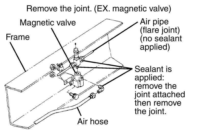
(2)For replacement of joint in a place with poor workability, remove the auxiliaries with the joint attached then remove the joint.
EN00Z08020200003
GENERAL INTRODUCTION (CHASSIS)GN02–18
To the tapered thread of the air pipe joint is applied the sealant "LOC-TITE #575". Follow the procedure below to remove/attach the piping.
(3)In the event of air leakage after sealant is applied and piping attached, retightening cannot check the air leakage. Follow the steps (1) and (2) to reassemble the piping.
Tightening torque of tapered joint Unit: N m {kgf cm, lbf ft}
SAPH00Z080200022SAPH00Z080200021
TakeNOTICEspecial care not to let dirt and foreign matters enter the piping.
Less than 5
REPLACEMENT METHODEN00Z08020200004
1.INSTALLATION OF A ONE-TOUCH JOINT joint
SinceNOTICEthe function and quality of nylon tubes and joints are guaranteed as tube and joint sets, the use of parts other than Hino Genuine Parts must be
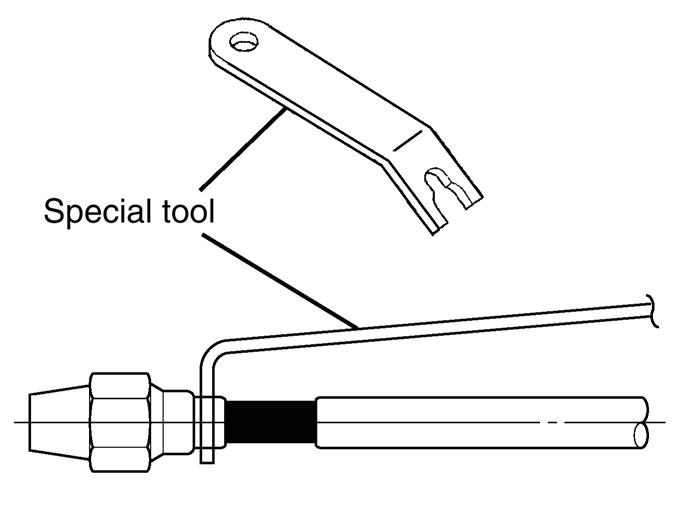
(1)Make sure there is no dirt or grease stuck to the connector end. If the end is dirty, clean it thoroughly by air blowing or other means. (2)Using the special tool for removing the nylon tube to push the connector end, pull off the nylon tube with your hand in one stroke, without stopping partway, pulling the tube in the connector axial direction.
2.REMOVAL OF A ONE-TOUCH JOINT
• In this vehicle, nylon tubes are used for all the air tubes except those on the charge line and the rear axle, the tubing for the wheel power signal, a portion of the accessory system tubing, and for the unloader tubing, and it is also used in joints, depending on the connection conditions of the two types of joints; one-touch joints and caulking joints.
SST: Puller
3/8 in.18-23 {0.71-0.91}
JOINT AND CAULKING JOINT
DIAMETER
SAPH00Z080200025
Nylon
One-touch
INSTALLATION(S0942-11490)OFAONE-TOUCH
Caulking joint SAPH00Z080200023
• Make sure the joint interior is free of dirt grease. If the interior is dirty, clean it thoroughly by air blowing or other means.
1/4 in.14-19 {0.55-0.75}
NYLON TUBE
• Cut off the tube end where the tube surface is scarred by the joint pinch marks, and make sure that the part of the tube inserted into the joint has no surface damage. If the tube is damaged, cut off the damaged part (provided that the tube length is more than sufficient).
UseNOTICEthe special nylon tube cutter when cutting the nylon tube, and cut the tube so that the angle of the cut end to the axial center is 85-95 .
Insertion length
NYLON TUBE REPLACEMENT METHOD
INSERTION LENGTH mm {in.}
1/2 in.21-26 {0.83-1.02}
˚ SAPH00Z080200026
NYLON TUBE INSERTION LENGTH
GENERAL INTRODUCTION (CHASSIS) GN02–19
SAPH00Z080200024tube
1.ONE-TOUCHavoided.JOINT
(Outside diameter x inside diameter)
• Do not attach a welding equipment clamp near the nylon tube.
NutsNOTICEmust be tightened to 5 - 35 C.
4.ASSEMBLING THE CAULKING JOINT (AFTER THE TUBE HAS FIRST BEEN REMOVED FROM THE JOINT AND THEN REINSTALLED IN THE SAME PLACE)
During boring, welding, sanding, and other work, protect nylon tubes from tools, cuts, heat sources, and sparks, or remove the nylon tubes beforehand.
•
marksSAPH00Z080200027
1/2 in.30 {1.18} 3/8 in.65 {2.56} 1/2 in.70 {2.76}
(3)Always check air leakage after assembling the joint. If air is leaking from the joint, continue tightening the sleeve nut until the leak stops.
•NOTICEDuring
• Do not pour battery fluid or other acidic fluid on the nylon tube.
• Do not bend the nylon tube beyond the nylon tube bending radius R values shown in the following table. Also, do not use the remaining portion of a tube that has broken due to overbend-
(1)Make aligning marks on the connector and union to mark their positions before loosening the nut.
1/4 in.20-26 {200-270, 15-19}
3.8 in.35-45 {350-460, 26-33} 1/2 in.50-60 {500-610, 37-44}
repair or other work, make sure the temperature limit of the nylon tube is within -40-90 C, especially during paint drying work.
DIAMETERSTIGHTENING TORQUE
(4)If the air leak does not stop, replace the tube, sleeve, and insert with new parts. If the air leak still continues, replace the nut and connector / union.
3.NYLON TUBE NUT TIGHTENING TORQUEUnit: N m {kgf cm, lbf ft}
(2)When re-assembling the joint, tighten the nut until the pre-disassembly position (position of aligning marks) is reached, and then tighten the nut 60 more.
MINIMUM BENDING RADIUS DURING HANDLING: R mm {in.}
• Press in the tube so that it does not move (will not come out), and tighten the sleeve nut with the tightening tool to the torque shown in the following table.
GENERAL INTRODUCTION (CHASSIS)GN02–20
•
Before inserting the tube, mark the insertion length on the tube with a white-out pen or similar implement, in accordance with the dimensions, "ONE-TOUCH JOINT NYLON TUBE INSERTION LENGTH." Then insert the tube firmly in place as far as the marked point.
2.INSTALLATION OF A CAULKING JOINT
ing.NUT
Aligning
OUTSIDE DIAMETER OF TUBE
for bolts
Bolt strength identification
Nomenclature
If they are not re-usable, parts that are equivalent to the original parts in dimensions, strength, and thread pitch must be
bolts are marked with identification numbers indicating the strength of the bolts. The markings are shown below.
4.When replacing bolts, be careful to use bolts with the same markings as the original bolts.
1.Most threaded fasteners on the Hino trucks series are metric. Be careful not to mix them up with threaded fasteners using the inch Mismatchedsystem. or incorrect bolts, nuts and screws can cause damage or malfunction, resulting in personal injury and/or property
EN00Z08021200001
Metric systemM12-1.7525DTL P 7 T L D 7 9 D-Nominal DiameterP-Property Class (millimeters)(bolt strength) L-Length (millimeters)T-Thread Pitch (thread width crest to crest millimeters)
Metric Bolts P Identification class numbers correspond to bolt strength. Increasing numbers represent increasing strength.
GENERAL INTRODUCTION (CHASSIS) GN02–21
METRIC FASTENERS
2.Whendamage.bolts,
nuts and screws are removed from the vehicle, they should be kept for reuse whenever possible.
3.Mostselected.original
METRIC INFORMATION
Bolt SAPH00Z080200028