Illustration 1 g03687208
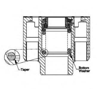
1. Use Tooling (C) to install shims (62) and bearing cups (61) into center section (3).


Illustration 2 g03687131
2. Use Tooling (C) and a suitable press to install bearing cup (59). Install bearing cup (59).

3. Install bearings (58) into front pump housing (27).
Note: There are two (2) Brass Pins (which are used to hold the bearings in place) in the front pump housing.
Illustration 3 g03687122
4. Apply Tooling (E) to the outer diameter of lip seal (57). Use Tooling (C) and a suitable press to install lip seal (57) into retainer (55). Install lip seal (57)
Illustration 4 g03687069
5. Install O-ring seal (56) onto retainer (55).


Illustration 5 g03687012
6. Install retainer (55) and bolts (54) onto front pump housing (27). Tighten bolts (54) to a torque of 9.5 ± 0.2 N·m (84.1 ± 1.8 lb in).

Illustration 6 g03688748
7. Install sleeves (53) into the swashplate.
Illustration 7 g03717223


To prevent possible injury, follow the established assembly procedure and wear protective equipment.
b. Use Tooling (D) and a suitable press to install retainer (50), spring (49), and retainer (48) onto actuator (47).


Illustration 10 g03688741
c. Install ring (42) onto shaft (43). Install shaft (43), actuator assembly (44), plate (45), and shims (46) onto swashplate (37).
Illustration 11 g03688737
d. Install pistons (40) into plate (41).
Illustration 12 g03688733
Illustration 13 g03688725
Illustration 14 g03688714
e. Install pistons (40) and plate (41) onto swashplate (37).
f. Use a feeler gauge to measure the gap between retainer (38) and plate (41). Add shims (39) to achieve a clearance of 0.010 to 0.030 mm (0.0004 to 0.0012 inch).
g. Apply Tooling (F) to bolts (36). Install shims (39), retainer (38), and bolts (36).


h. Repeat Steps 8.f and 8.g for the remaining rotating group.
Illustration 15 g03715525
Front pump shaft assembly
Illustration 16 g03718409
Rear pump shaft assembly
9. Raise temperature of bearing cone (30) to 121 °C (250 °F). Install bearing cone (30) onto shaft assembly (29).
10. Apply Tooling (E) to the outer diameter of guide (31). Install guide (31) with the tapered edge facing away from bearing cone (30).


11. Use the following procedure to determine the end play for the shaft:
Illustration 17 g03689822
a. Install shaft assembly (29) into the housing.
b. Raise the temperature of bearing (24) to 121 °C (250 °F). Install ring (25) and bearing (24) onto the shaft.
Illustration 18 g03687208
c. Install the shims (61) and bearing cups (60) into center section (3).

Illustration 19 g03689827
d. Install center section (3) and Tooling (G). Tighten Tooling (G) to a torque of 110 N·m (80 lb ft).

Illustration 20 g00682185
e. Use a rubber mallet to seat the shaft into the bearing cup.

Illustration 21 g06131423
f. Install a suitable bolt into the end of the shaft. Install Tooling (H), as shown. Use a lever to measure the amount of end play in the shaft. Add the appropriate thickness of shims to achieve an end play of 0.020 to 0.070 mm (0.0008 to 0.0028 inch).


Note: The shims are located in the center section under the bearing cup.
g. Remove the center section.
Illustration 22 g03689822
h. Remove shaft assembly (29) from the housing.
i. Use Tooling (B) to remove ring (25) and bearing (24) from shaft (29).
j. Repeat Steps 11.a through 11.i for the driven end of the pump.

Improper assembly of parts that are spring loaded can cause bodily injury.
To prevent possible injury, follow the established assembly procedure and wear protective equipment.
12. Install washers (34), spring (35), and inner and outer bushings (33) into barrel assembly (16).
13. Use a suitable press to compress spring (35).


14. Install retaining ring (32) into barrel assembly (16).
15. Repeat Steps 12 through 14 for the remaining barrel assembly.
16. Use the following procedure to determine the sliding block play:
a. Install the pins and bearings (58).
Note: The pins must be installed to a depth below the bearings.
Illustration 26 g03719080
Dimension (A)
b. Install the swashplate assembly into the pump housing.
c. Use a depth gauge to level the swashplate assembly inside the pump housing. Take several measurements to make sure that the swashplate is level.

d. Install a 5.0 mm (0.02 ft) ball bearing into each spherical hole on the swashplate assembly.
e. Use the depth gauge to measure the distance from the face of the pump housing to the top of the ball bearings. This measurement will be referred to as Dimension (A).
Illustration 27 g03717960
Dimension (B)
f. Measure the length of lubrication tubes (17). This measurement will be referred to as Dimension (B).

Illustration 28 g03719155 Dimension (C)
g. Remove the shims from the holes in the head assembly. Use the depth gauge to measure the depth of the holes. This measurement will be referred to as Dimension (C).
h. Use the following formula to determine the number of shims needed:
A + C + 5 mm (0.19685 inch) = B + 0.01 to 0.15 mm (0.00039 to 0.00590 inch)
Illustration 29 g03718031
17. Install pistons (40) into barrel assembly (16).


Illustration 30 g03718034
18. Install shaft (29) into barrel assembly (16).
Illustration 31 g06132601 Illustration 32 g00669010 19. Install Tooling (J) on the shaft. Tooling (J) is used to prevent damage to the lip seal. 20. Raise the temperature of Tooling (J) to shrink into place.


Illustration 33 g06075456

Illustration 34 g06075460
21. Install spacer (25) and bearing cone (24). 22. Repeat Steps 16 through 21 for the other rotating group.

Illustration 35 g06073901 23. Apply a paint mark on one drive shaft spline that aligns with the center of one of the kidney slots on the cylinder barrel.

Illustration 36 g06073916
24. On the coupling, select any spline and apply a paint mark along the root of the spline. Apply a paint mark on each end of the coupling as well.
Illustration 37 g06073923
Use the rotating group for the rear pump for this step.

25. Install the coupling onto the drive shaft at various positions, until the paint mark on the coupling aligns between two kidney slots on the cylinder barrel.

Illustration 38 g06073933
26. Slightly lift the Coupling, and then apply a paint mark on the drive shaft spline that aligns with the paint mark on the Coupling.

Illustration 39 g06074244
27. The cylinder barrels for the front pump and rear pump must be properly “timed” to insure smooth, quiet operation of the pump. Illustration 39 shows how the two cylinder barrels are set in properly “timed” positions. Use the paint marks to ensure that the front pump and rear pump must be properly “timed” during final assembly.

Illustration 40 g06075941
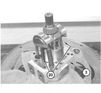
28. Install the O-ring seals and the back-up rings on lubrication tubes (20).


Illustration 41 g06075970
29. Install lube tubes (20) and the shims determined in Step 16.h.
Illustration 42 g06075990
30. Install port plate (21).
Illustration 43 g06076008
31. Install rotating group (26) for the front pump onto center section (3).
Illustration 44 g06076026
32. Make sure that both actuator pistons and lube tubes (20) are in the appropriate cavities on center section (3).


Illustration 45 g06076039 33. Install front pump housing (27). Illustration 46 g03689827 34. With the pump still oriented as shown in Step 33, install Tooling (G). Do not clamp firmly - you only need to hold them together to reposition the pump. Reposition pump as shown. 35. Remove Tooling (G).


Illustration 47 g06076158
36. Install coupling (22) onto the tail-splines of the front pump drive shaft. Orient the coupling so that the paint marks on the coupling and the drive shaft align with each other.


Illustration 48 g03670277
Note: Install the lubrication tubes and the shims determined in Step 16.h.
37. Install lube tubes (17) and the shims.
38. Install port plate (18) onto center section (3). Illustration 49

39. Install rotating group (11) onto center section (3). Orient the rotating group so that the paint marks on the coupling and the drive shaft align with each other.

Illustration 50 g06074722 40. Install connection rods (10). 41. Install new self-adhesive dampener strips to the connection rods marked (10A).
Illustration 51 g03669361 42. Install bearing (8) and bearing cup (9) into rear pump housing (7).
Note: There are two Brass Pins (which are used to hold the bearings in place) remaining in the front pump housing. If undamaged, leave the brass pins in the front pump housing.

Illustration 52 g03669360
43. Use Tooling (A) and a suitable lifting device to install rear pump housing (7). Install rear pump housing (7).
Illustration 53 g06128833
Improper assembly of parts that are spring loaded can cause bodily injury.
To prevent possible injury, follow the established assembly procedure and wear protective equipment.
44. Install the O-ring seals and nuts (6). Tighten nuts (6) to a torque of 110 N·m (81 lb ft).

45. Apply Tooling (F) to bolts (4). Install bolts (4).

46. Install the O-ring seals, valve group (2), the washers, and bolts (1) to center section (3).

End By:
a. Install the piston pump (implement).
Copyright 1993 - 2021 Caterpillar Inc.
All Rights Reserved. Private Network For SIS Licensees.
Tue Dec 7 23:59:39 UTC+0800 2021
Illustration 1 g06299941
1. Install backup ring (65) and O-ring seal (64) onto stopper (63).
Illustration 2 g06304626
2. Install stopper (63) into the pump body.
3. Install plugs (62).


Illustration 3 g06299933

Illustration 4 g06299927
4. Install setscrew (60) and nut (61) onto cover (59). Use Tooling (E) and adjust setscrew (60) to the height recorded during the disassembly. Tighten nut (61) to a torque of 240 ± 24 N·m (175 ± 15 lb ft).


Illustration 5 g06299921
5. Install cover (59) and bolts (58) onto pump body (23). Tighten bolts (58) to a torque of 330 ± 33 N·m (240 ± 20 lb ft).
Illustration 6 g06299916
6. Install O-ring seals (57) into pump body (23).

Illustration 7 g06299910
7. Install the O-ring seal and adapter (56) into pump body (23).


Illustration 8 g06299901
8. Install plug (55), the O-ring seal, and plug (54) into pump body (23).

Illustration 9 g06299892
9. Install bearing (53) into pump body.
Note: Bearing (53) must align with the dowel in the pump body.
Illustration 10 g06299886
10. Install piston (52) into pump body (23).


Illustration 11 g06299880
11. Install backup ring (51) and O-ring seal (50) onto stopper (49).
Illustration 12 g06304632
12. Install stopper (49) into the pump body.
Illustration 13 g06299861
13. Install plate (48) onto swashplate assembly (45).
Illustration 14 g06299855
14. Install swashplate assembly (45), O-ring seals (46), and O-ring seals (47) into pump body (23).
Note: Ensure that swashplate (45) engages the piston and the bearing properly.
Illustration 15 g06304636
15. Use Tooling (G) and a suitable press to install bearing (44) onto shaft assembly (41).


Illustration 16 g06299676
16. Install retaining ring (43) onto shaft assembly (41).

Illustration 17 g06299675
17. Install lip seals (42) into seal carrier (40).
Illustration 18 g06299674
18. Use a soft faced hammer to install shaft assembly (41) and seal carrier (40) into pump body (23).


Illustration 19 g06299673
19. Install retaining ring (39) into pump body (23).

Illustration 20 g06299671
20. Install springs (38) and bearing (37) onto barrel assembly (36).

Illustration 21 g06299648
21. Install retainer (35) and pistons (34) onto barrel assembly (36).

Illustration 22 g06299579
22. Install rotating group (33) into pump body (23).

Illustration 23 g06299578
23. Use Tooling (F) and a suitable lifting device to install pump body (23) onto Tooling (A). Pump body (23) weighs approximately 60 kg (133 lb).

Illustration 24 g06299534
24. Install setscrew (31) and nut (32) onto head (22). Use Tooling (E) and adjust setscrew (31) to the height recorded during the disassembly. Tighten nut (32) to a torque of 240 ± 24 N·m (175 ± 15 lb ft).

