
2005-06 RESTRAINTS SRS (Supplemental Restraint System) - Odyssey
2005-06 RESTRAINTS
SRS (Supplemental Restraint System) - Odyssey
COMPONENT LOCATION INDEX
Fig. 1: Identifying SRS Components Location (1 Of 2) Courtesy of AMERICAN HONDA MOTOR CO., INC.

PRECAUTIONS AND PROCEDURES
GENERAL PRECAUTIONS
Please read the following precautions carefully before performing the airbag systemservice. Observe the instructions described in this information, or the airbags could accidentally deploy and cause damage or injuries.

Except when performing electrical inspections, always turn the ignition switch OFF, ground the SCS line with the HDS to take the PCM out of active status, disconnect the negative cable fromthe battery, and wait at least 3 minutes before beginning work.
NOTE:The SRS memory is not erased even if the ignition switch is turned OFF or the battery cables are disconnected from the
Fig. 2: Identifying SRS Components Location (2 Of 2) Courtesy of AMERICAN HONDA MOTOR CO., INC.Use replacement parts which are manufactured to the same standardsand quality as the original parts. Do not install used SRS parts. Use only new partswhen making SRS repairs. Carefully inspect any SRS part before you install it. Do not install any part that shows signs of being dropped or improperly handled, such as dents, cracks or deformation.
Before removing any of the SRS parts (including the disconnection of the connectors), always disconnect the SRS connector. Use only a digital multimeter to check the system. If it is not a Honda multimeter, make sure its output is 10 mA (0.01 A) or less when switched to the lowest value in the ohmmeter range. A tester with a higher output could cause accidental deployment and possible injury. Do not put objectson the front passenger's airbag.
 Fig. 3: Inspecting SRS Parts Courtesy of AMERICAN HONDA MOTOR CO., INC.
The original radio and navigation systemhave a coded theft protection circuit. Be sure to get the customer'santi-theft codesand write down the radio station and XM channel presets before disconnecting the battery negative cable. After reconnecting the battery, reset the power sliding door control unit (see RESETTING THE POWER SLIDING DOOR CONTROL UNIT ), and reset the power tailgate control unit (see RESETTING THE POWER TAILGATE CONTROL UNIT ).
Before returning the vehicle to the customer, enter the radio code, the navigation code, then enter the radio station and XM channel presets; set the clock.
STEERING-RELATED PRECAUTIONS
Cable Reel Alignment
Misalignment of the cable reel could cause an open in the wiring, making the SRS system, remote steering wheel controls, and the horn inoperative. Center the cable reel (see step 6 in INSTALLATION ), whenever the following is performed.
- Installation of the steering wheel
- Installation of the cable reel
- Installation of the steering column
- Other steering-related adjustment or installation
Do not disassemble the cable reel.
Do not apply grease to the cable reel.
If the cable reel shows any signs of damage, replace it with a new one. For example, if it does not rotate smoothly, replace the cable reel.
AIRBAG HANDLING AND STORAGE
Do not disassemble an airbag. It hasno serviceable parts. Once an airbag has been deployed, it cannot be repaired or reused.
For temporary storage of an airbag during service, observe the following precautions.
Store the removed airbag with the pad surface up. Never put anything on the airbag.
To prevent damage to the airbag, keep it away fromany oil, grease, detergent, or water.
 Fig. 4: Storing Removed Airbag With Pad Surface Up Courtesy of AMERICAN HONDA MOTOR CO., INC.
Store the removed airbag on a secure, flat surface away fromany high heat source (exceeding 200°F/ 93°C).
 Fig. 5: Keeping Airbag Away From Oil, Grease, Detergent Or Water Courtesy of AMERICAN HONDA MOTOR CO., INC.
Thank you very much for your reading. Please Click Here. Then Get COMPLETE MANUAL.NOWAITING

NOTE:
If there is no response to click on the link above, please download the PDF document first and then clickonit.
Never performelectrical inspections to the airbags, such as measuring resistance. Do not position yourself in front of the airbag during removal, inspection, or replacement.
 Fig. 6: Do Not Store Airbag Near High Heat Source
Courtesy of AMERICAN HONDA MOTOR CO., INC.
Fig. 6: Do Not Store Airbag Near High Heat Source
Courtesy of AMERICAN HONDA MOTOR CO., INC.
For proper disposal of a damaged airbag, refer to airbag disposal (see AIRBAG DISPOSAL ).
The side curtain airbag inflator assembly is a long, jointed part containing an inflator (A), a flexible bag (B), and an adapter pipe (C).
 Fig. 7: Precaution During Airbag Removal, Inspection Or Replacement Courtesy of AMERICAN HONDA MOTOR CO., INC.
Fig. 8: Identifying Side Curtain Airbag Inflator Assembly

Courtesy of AMERICAN HONDA MOTOR CO., INC.
When removing or installing the side curtain airbag inflator assembly, never handle the adapter pipe.
SRS UNIT, IMPACT SENSORS, DRIVER'S SEAT POSITION SENSOR, FRONT PASSENGER'S WEIGHT SENSORS AND UNIT, REAR SAFING SENSOR, AND ROLL RATE SENSOR
Be careful not to bump or impact the SRS unit, front impact sensors, side impact sensors, rear safing sensor, or roll rate sensor whenever the ignition switch is ON (II), or for at least 3 minutesafter the ignition switch is turned OFF.
During installation or replacement, be careful not to bump (by impact wrench, hammer, etc.) the area around the SRS unit, front impact sensors, the side impact sensors, rear safing sensor, or roll rate sensor. The airbags could accidentally deploy and cause damage or injury.
Courtesy of AMERICAN HONDA MOTOR CO., INC.
After a collision in which the airbags or seat belt tensioners were deployed, replace the SRS unit, front impact sensors, and other related components (see COMPONENT REPLACEMENT/INSPECTION AFTER DEPLOYMENT ). After a collision in
 Fig. 9: Precaution For Bump Around SRS Unit, Front Impact Sensors , Side Impact Sensors, Rear Safing Sensor Or Roll Rate Sensor
which a side airbag deployed, replace the side impact sensor on the deployed side and the SRS unit. After a collision in which a side airbag and a side curtain airbag deployed, replace the side impact sensorson the deployed side and SRS unit. After a collision in which the airbagsor the side airbagsdid not deploy, inspect for any damage or any deformation on the SRS unit, front impact sensors, the side impact sensors, roll rate sensor and rear safing sensor. If there is any damage, replace the SRS unit and/or the sensors
Fig. 10: Precaution Of SRS Unit
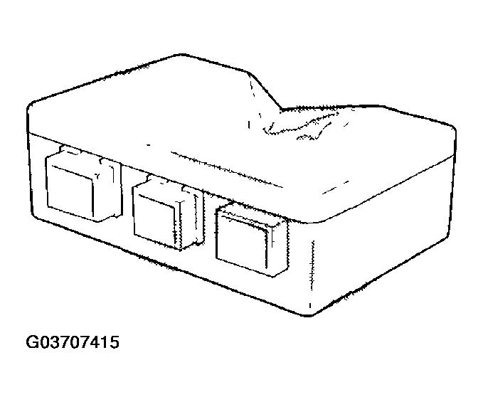
Courtesy of AMERICAN HONDA MOTOR CO., INC.
Do not disassemble the SRS unit, front impact sensors, side impact sensors, driver's seat position sensor, front passenger's weight sensor unit, front passenger'sweight sensors, rear safing sensor, or roll rate sensor.
Turn the ignition switch OFF, disconnect the battery negative cable and wait at least 3 minutesbefore beginning installation or replacement of the SRS unit, or disconnecting the connectors fromthe SRS unit.
Be sure the SRS unit, front impact sensors, side impact sensors, rear safing sensor and roll
rate sensor are installed securely with the mounting bolts torqued to 9.8 N.m(1.0 kgf.m, 7.2 lbf.ft)
Do not spill water or oil on the SRS unit, the side impact sensors or roll rate sensor, and keep themaway fromdust.
Store the SRS unit, front impact sensors, side impact sensors, rear safing sensor and roll rate sensor in a cool (less than 104°F/40°C) and dry (lessthan 80% relative humidity, no moisture) area.
WIRING PRECAUTIONS
Some of the SRS wiring can be identified by special yellow outer covering, and the SRS connectors can be identified by their yellow color. Observe the following instructions.
Never attempt to modify, splice, or repair SRS wiring. If there is an open or damage in SRS wiring or terminals, replace the harness.
Be sure to install the harnesswires so they do not get pinched or interfere with other parts.
 Fig. 11: Never Attempt To Modify, Splice Or Repair SRS Wiring Courtesy of AMERICAN HONDA MOTOR CO., INC.