OPERATOR’S MANUAL
TV6070
Tractor
Part number 47538609
2nd edition English
October 2013
Replaces part number 87575273
Contents 1 GENERAL INFORMA TION Read the Manual 1 - 1 Note the owner . . . . . . . . . . . . . . . . . . . . . . . . . . . . . . . . . . . . . . . . . . . . . . . . . . . . . . . . . . . . . . . . . . . . . . . . . . . 1 - 1 Emissions warranty 1 - 2 Electro - Magnetic Compatibility (EMC) . . . . . . . . . . . . . . . . . . . . . . . . . . . . . . . . . . . . . . . . . . . . . . . . . . . . . 1 - 3 CNH America LLC technical manuals 1 - 4 Y our tractor 1 - 5 Manual storage . . . . . . . . . . . . . . . . . . . . . . . . . . . . . . . . . . . . . . . . . . . . . . . . . . . . . . . . . . . . . . . . . . . . . . . . . . . . . 1 - 6 T ractor intended use 1 - 6 Product identification . . . . . . . . . . . . . . . . . . . . . . . . . . . . . . . . . . . . . . . . . . . . . . . . . . . . . . . . . . . . . . . . . . . . . . . 1 - 7 Machine orientation 1 - 8 Component location 12 SAFETY INFORMA TION Safety rules 2 - 1 Proposition 2 - 2 Safety rules . . . . . . . . . . . . . . . . . . . . . . . . . . . . . . . . . . . . . . . . . . . . . . . . . . . . . . . . . . . . . . . . . . . . . . . . . . . . . . . . . 2 - 3 Ecology and the environment 2Roll Over Protection Structure (ROPS) . . . . . . . . . . . . . . . . . . . . . . . . . . . . . . . . . . . . . . . . . . . . . . . . . . . 2 - 1 1 Safety signs 2Articulation lock . . . . . . . . . . . . . . . . . . . . . . . . . . . . . . . . . . . . . . . . . . . . . . . . . . . . . . . . . . . . . . . . . . . . . . . . . . . . 23 CONTROLS / INSTRUMENTS ACCESS T O OPERA T OR'S PLA TFORM Cab - Access / Exit . . . . . . . . . . . . . . . . . . . . . . . . . . . . . . . . . . . . . . . . . . . . . . . . . . . . . . . . . . . . . . . . . . . . . . . 3 - 1 OPERA T OR'S SEA T Overview 3 - 2 Control identification . . . . . . . . . . . . . . . . . . . . . . . . . . . . . . . . . . . . . . . . . . . . . . . . . . . . . . . . . . . . . . . . . . . . 3 - 2 FOR W ARD CONTROLS Steering column controls 3 - 4 Front console controls 3 - 6 Engine - end pedal controls 3 - 7 LEFT - HAND SIDE CONTROLS Park brake 3 - 8 Left side post controls . . . . . . . . . . . . . . . . . . . . . . . . . . . . . . . . . . . . . . . . . . . . . . . . . . . . . . . . . . . . . . . . . . 3 - 8 RIGHT - HAND SIDE CONTROLS Seat console controls . . . . . . . . . . . . . . . . . . . . . . . . . . . . . . . . . . . . . . . . . . . . . . . . . . . . . . . . . . . . . . . . . . . 3 - 9 Right side post controls 3 -
REAR W ARD CONTROLS Cab - end pedal controls . . . . . . . . . . . . . . . . . . . . . . . . . . . . . . . . . . . . . . . . . . . . . . . . . . . . . . . . . . . . . . . . 3Cab - end flow control adjusters 3Rear window . . . . . . . . . . . . . . . . . . . . . . . . . . . . . . . . . . . . . . . . . . . . . . . . . . . . . . . . . . . . . . . . . . . . . . . . . . . 3OVERHEAD CONTROLS Overview . . . . . . . . . . . . . . . . . . . . . . . . . . . . . . . . . . . . . . . . . . . . . . . . . . . . . . . . . . . . . . . . . . . . . . . . . . . . . . 3Climate controls . . . . . . . . . . . . . . . . . . . . . . . . . . . . . . . . . . . . . . . . . . . . . . . . . . . . . . . . . . . . . . . . . . . . . . . 3Radio 3EXTERIOR CONTROLS Manually external mirrors 3ELECTRONIC INSTRUMENT CONTROL SYSTEM Overview 3Calibration 3Setting service intervals . . . . . . . . . . . . . . . . . . . . . . . . . . . . . . . . . . . . . . . . . . . . . . . . . . . . . . . . . . . . . . . 34 OPERA TING INSTRUCTIONS COMMISSIONING THE UNIT Before starting the engine 4 - 1 TING THE UNIT Normal engine starting 4 - 6 Cold temperature operation . . . . . . . . . . . . . . . . . . . . . . . . . . . . . . . . . . . . . . . . . . . . . . . . . . . . . . . . . . . . 4 - 9 OPPING THE UNIT Stopping the machine and the engine . . . . . . . . . . . . . . . . . . . . . . . . . . . . . . . . . . . . . . . . . . . . . . . . . 4 - 1 1 MOVING THE UNIT Hydrostatic system operation . . . . . . . . . . . . . . . . . . . . . . . . . . . . . . . . . . . . . . . . . . . . . . . . . . . . . . . . . . 4Dif ferential lock 4Electronic instrument control system operation . . . . . . . . . . . . . . . . . . . . . . . . . . . . . . . . . . . . . . . 4Reversable fan (if equipped) 4 -
TRANSPOR
ROAD
T ractor warning lamps and Slow Moving V ehicle (SMV) symbol . . . . . . . . . . . . . . . . . . . . . . . 5 - 1 Operating the tractor warning lamps 5 - 3 Implement warning lamps and Slow Moving V ehicle (SMV) symbol 5 - 3 Safety chain . . . . . . . . . . . . . . . . . . . . . . . . . . . . . . . . . . . . . . . . . . . . . . . . . . . . . . . . . . . . . . . . . . . . . . . . . . . . 5 - 4
5
T OPERA TIONS
TRANSPOR T
RECOVER Y TRANSPOR T
WORKING OPERA TIONS
THREE POINT HITCH
SHIPPING TRANSPOR
Securing the tractor for shipping . . . . . . . . . . . . . . . . . . . . . . . . . . . . . . . . . . . . . . . . . . . . . . . . . . . . . . . 5 - 5
T
Safety rules . . . . . . . . . . . . . . . . . . . . . . . . . . . . . . . . . . . . . . . . . . . . . . . . . . . . . . . . . . . . . . . . . . . . . . . . . . . . . 5 - 6 Moving a disabled tractor 5 - 7 6
GENERAL INFORMA TION External lighting . . . . . . . . . . . . . . . . . . . . . . . . . . . . . . . . . . . . . . . . . . . . . . . . . . . . . . . . . . . . . . . . . . . . . . . . 6 - 1 Operating external lighting 6 - 2 POWER T AKE OFF (PT Safety rules 6 - 4 Changing the Power T ake - f (PT shaft . . . . . . . . . . . . . . . . . . . . . . . . . . . . . . . . . . . . . . . . . 6 - 5 Connecting the Power T ake - f (PT 6 - 7 Power T ake - f (PT operation . . . . . . . . . . . . . . . . . . . . . . . . . . . . . . . . . . . . . . . . . . . . . . . . . . . 6 - 8
Overview . . . . . . . . . . . . . . . . . . . . . . . . . . . . . . . . . . . . . . . . . . . . . . . . . . . . . . . . . . . . . . . . . . . . . . . . . . 6Hitch position setup 6Hitch linkage adjustments . . . . . . . . . . . . . . . . . . . . . . . . . . . . . . . . . . . . . . . . . . . . . . . . . . . . . . . . . 6Using the external cab - end hitch control switches 6Hitch capture (automatic mode) . . . . . . . . . . . . . . . . . . . . . . . . . . . . . . . . . . . . . . . . . . . . . . . . . . . 6Cab - end implement cab clearance 6Engine - end implement hood clearance . . . . . . . . . . . . . . . . . . . . . . . . . . . . . . . . . . . . . . . . . 6DRA WBARS AND T OWING A ACHMENTS Safety rules . . . . . . . . . . . . . . . . . . . . . . . . . . . . . . . . . . . . . . . . . . . . . . . . . . . . . . . . . . . . . . . . . . . . . . . . 6Cab - end (rear) drawbar 6Engine - end (front) drawbar . . . . . . . . . . . . . . . . . . . . . . . . . . . . . . . . . . . . . . . . . . . . . . . . . . . . . . . . 6Connecting the drawbar 6AUXILIAR Y POWER CONNECTIONS External power and lighting connections 6HYDRAULIC REMOTE CONTROL V VES V alve couplers and connections 6Auxiliary hydraulic drive system (if equipped) . . . . . . . . . . . . . . . . . . . . . . . . . . . . . . . . . . . . . 6Remote control operation 6Operating continuous flow hydraulic equipment . . . . . . . . . . . . . . . . . . . . . . . . . . . . . . . . . . . 6Operating auxiliary hydraulic drive system (if equipped) 6 -
BALLASTING THE TRACT Guidelines . . . . . . . . . . . . . . . . . . . . . . . . . . . . . . . . . . . . . . . . . . . . . . . . . . . . . . . . . . . . . . . . . . . . . . . . . 6W cast metal and liquid 6Ballasting weight calculation chart . . . . . . . . . . . . . . . . . . . . . . . . . . . . . . . . . . . . . . . . . . . . . . . . 6WHEELS AND TIRES T ire safety . . . . . . . . . . . . . . . . . . . . . . . . . . . . . . . . . . . . . . . . . . . . . . . . . . . . . . . . . . . . . . . . . . . . . . . . . 6Pressure and load ratings 6Wheel tread settings . . . . . . . . . . . . . . . . . . . . . . . . . . . . . . . . . . . . . . . . . . . . . . . . . . . . . . . . . . . . . . . 67 MAINTENANCE GENERAL INFORMA TION Safety rules 7 - 1 Engine hood . . . . . . . . . . . . . . . . . . . . . . . . . . . . . . . . . . . . . . . . . . . . . . . . . . . . . . . . . . . . . . . . . . . . . . . . . . . . 7 - 2 Filling the fuel tank 7 - 3 Bleeding the fuel injection system . . . . . . . . . . . . . . . . . . . . . . . . . . . . . . . . . . . . . . . . . . . . . . . . . . . . . . 7 - 4 Jacking the tractor 7 - 6 T ire and rim service . . . . . . . . . . . . . . . . . . . . . . . . . . . . . . . . . . . . . . . . . . . . . . . . . . . . . . . . . . . . . . . . . . . . . 7 - 7 Lubricants and capacities 7 - 9 Consumables - Engine oil . . . . . . . . . . . . . . . . . . . . . . . . . . . . . . . . . . . . . . . . . . . . . . . . . . . . . . . . . . . . 7Consumables - Diesel fuel 7 - 1 1 Consumables - Biodiesel fuel 7Organic Acid T echnology (OA coolant . . . . . . . . . . . . . . . . . . . . . . . . . . . . . . . . . . . . . . . . . . . . . . . 7Fuse and relay locations 7Electrical system specifications . . . . . . . . . . . . . . . . . . . . . . . . . . . . . . . . . . . . . . . . . . . . . . . . . . . . . . . 7Maintenance chart notes 7MAINTENANCE CHAR T Maintenance Chart 7When indicator lamp lights Air filter outer element 7Every hours daily Engine coolant level (Note 7Engine oil level . . . . . . . . . . . . . . . . . . . . . . . . . . . . . . . . . . . . . . . . . . . . . . . . . . . . . . . . . . . . . . . . . . . . . . . . 7Hydraulic hoses, tubes, and fittings . . . . . . . . . . . . . . . . . . . . . . . . . . . . . . . . . . . . . . . . . . . . . . . . . . . 7Radiator , oil cooler and air conditioner condenser 7Brake fluid reservoir level (Note . . . . . . . . . . . . . . . . . . . . . . . . . . . . . . . . . . . . . . . . . . . . . . . . . . . . 7Daily cleaning 7Every hours Cab - end axle oil level (Note . . . . . . . . . . . . . . . . . . . . . . . . . . . . . . . . . . . . . . . . . . . . . . . . . . . . . . . . 7Windshield washer fluid level 7Upper and lower articulation pin 7 -
Front and rear steering cylinder pins . . . . . . . . . . . . . . . . . . . . . . . . . . . . . . . . . . . . . . . . . . . . . . . . . . 7Engine - end axle oscillation pivot 7Fuel filter / water separator . . . . . . . . . . . . . . . . . . . . . . . . . . . . . . . . . . . . . . . . . . . . . . . . . . . . . . . . . . . . . 7Cab air filters 7T ire pressure and condition . . . . . . . . . . . . . . . . . . . . . . . . . . . . . . . . . . . . . . . . . . . . . . . . . . . . . . . . . . . . 7Park brake linkage adjustment 7Three - point hitch . . . . . . . . . . . . . . . . . . . . . . . . . . . . . . . . . . . . . . . . . . . . . . . . . . . . . . . . . . . . . . . . . . . . . . 7Driveline articulation steady bearings 7First 300 hours Engine oil and filters 7Every 300 hours Engine air intake connections . . . . . . . . . . . . . . . . . . . . . . . . . . . . . . . . . . . . . . . . . . . . . . . . . . . . . . . . . 7Driveline articulation slip yokes 7Engine accessory drive belt . . . . . . . . . . . . . . . . . . . . . . . . . . . . . . . . . . . . . . . . . . . . . . . . . . . . . . . . . . . 7Wheel hardware torque 7Every 500 hours Engine - end axle oil level (Note . . . . . . . . . . . . . . . . . . . . . . . . . . . . . . . . . . . . . . . . . . . . . . . . . . . . . 7Fuel filters (Note 7Every 600 hours Engine oil and filters (Note 7Battery connections . . . . . . . . . . . . . . . . . . . . . . . . . . . . . . . . . . . . . . . . . . . . . . . . . . . . . . . . . . . . . . . . . . . 7Battery electrolyte level 7Starter connections . . . . . . . . . . . . . . . . . . . . . . . . . . . . . . . . . . . . . . . . . . . . . . . . . . . . . . . . . . . . . . . . . . . . 7Fuel tank hoses and connections 7Hydraulic oil filter (Note 7Hydrostatic oil filter (Note . . . . . . . . . . . . . . . . . . . . . . . . . . . . . . . . . . . . . . . . . . . . . . . . . . . . . . . . . . . 7Auxiliary hydraulic drive filter (if equipped) (Note 7Auxiliary hydraulic return filter (if equipped) (Note . . . . . . . . . . . . . . . . . . . . . . . . . . . . . . . . . . 7Every 1200 hours annually Cab air filters . . . . . . . . . . . . . . . . . . . . . . . . . . . . . . . . . . . . . . . . . . . . . . . . . . . . . . . . . . . . . . . . . . . . . . . . . . 7Hydraulic oil and filters (Note 7Engine - end axle oil . . . . . . . . . . . . . . . . . . . . . . . . . . . . . . . . . . . . . . . . . . . . . . . . . . . . . . . . . . . . . . . . . . . 7Radiator and heating system hoses 7Engine air filters (Note . . . . . . . . . . . . . . . . . . . . . . . . . . . . . . . . . . . . . . . . . . . . . . . . . . . . . . . . . . . . . . 7Crankcase breather 7Every 1200 hours two years Engine coolant 7 -
Every 1800 hours Fuel injectors 7required Engine idle speed . . . . . . . . . . . . . . . . . . . . . . . . . . . . . . . . . . . . . . . . . . . . . . . . . . . . . . . . . . . . . . . . . . . . . 7Cab floor 7Cab seat and upholstery 7Fuel tanks . . . . . . . . . . . . . . . . . . . . . . . . . . . . . . . . . . . . . . . . . . . . . . . . . . . . . . . . . . . . . . . . . . . . . . . . . . . . . 7Windshield wiper blades 7Brake fluid . . . . . . . . . . . . . . . . . . . . . . . . . . . . . . . . . . . . . . . . . . . . . . . . . . . . . . . . . . . . . . . . . . . . . . . . . . . . . 7ORAGE Placing storage . . . . . . . . . . . . . . . . . . . . . . . . . . . . . . . . . . . . . . . . . . . . . . . . . . . . . . . . . . . . . . . . . 7Removing from storage 7ELECTRICAL SYSTEM Auxiliary battery connections 7Headlamp adjustment . . . . . . . . . . . . . . . . . . . . . . . . . . . . . . . . . . . . . . . . . . . . . . . . . . . . . . . . . . . . . . . . . 7Front hood bulb replacement 7Roof warning lamp bulb replacement . . . . . . . . . . . . . . . . . . . . . . . . . . . . . . . . . . . . . . . . . . . . . . . . . 7Stop / tail / turn bulb replacement (cab) 7W ork light bulb replacement (cab mounted) . . . . . . . . . . . . . . . . . . . . . . . . . . . . . . . . . . . . . . . . . . . 78 TROUBLESHOOTING F AUL T CODE RESOLUTION Three - point hitch 8 - 1 ALARM(S) Critical alarms . . . . . . . . . . . . . . . . . . . . . . . . . . . . . . . . . . . . . . . . . . . . . . . . . . . . . . . . . . . . . . . . . . 8 - 2 Non - critical alarms 8 - 6 SYMPT OM(S) Engine 8Electrical system . . . . . . . . . . . . . . . . . . . . . . . . . . . . . . . . . . . . . . . . . . . . . . . . . . . . . . . . . . . . . . . . . . 8Hydraulic system 8Three - point hitch . . . . . . . . . . . . . . . . . . . . . . . . . . . . . . . . . . . . . . . . . . . . . . . . . . . . . . . . . . . . . . . . . . 8Cab 8Operation . . . . . . . . . . . . . . . . . . . . . . . . . . . . . . . . . . . . . . . . . . . . . . . . . . . . . . . . . . . . . . . . . . . . . . . . . . 8Hydrostatic system 8Brakes . . . . . . . . . . . . . . . . . . . . . . . . . . . . . . . . . . . . . . . . . . . . . . . . . . . . . . . . . . . . . . . . . . . . . . . . . . . . . 8Electronic instrument control system 8 -
9 SPECIFICA TIONS General specifications . . . . . . . . . . . . . . . . . . . . . . . . . . . . . . . . . . . . . . . . . . . . . . . . . . . . . . . . . . . . . . . . . . . . . . 9 - 1 V ehicle dimensions and maximum weights 9 - 5 Ground speeds . . . . . . . . . . . . . . . . . . . . . . . . . . . . . . . . . . . . . . . . . . . . . . . . . . . . . . . . . . . . . . . . . . . . . . . . . . . . . 9 - 5 ACCESSORIES Installation cab mounted accessories . . . . . . . . . . . . . . . . . . . . . . . . . . . . . . . . . . . . . . . . . . . . . . . . . . - 1 T ractor accessories - 4 Loader accessories . . . . . . . . . . . . . . . . . . . . . . . . . . . . . . . . . . . . . . . . . . . . . . . . . . . . . . . . . . . . . . . . . . . . . . . -
Read the Operator's Manual
Improper operation this vehicle can cause death serious injury Before using the make certain that every operator:
• instructed safe and proper use the
• Reads and understands the manual(s) pertaining the
• Reads and understands all safety decals the chine.

Note the owner
• Clears the area other
• Learns and practices safe use machine controls a safe, clear area before operating this machine a job
your responsibility observe pertinent laws and ulations and follow CNH America LLC instructions chine operation and
This manual contains important information about the safe adjustment and routine maintenance your tractor The manual divided into ten chapters outlined the table contents. Refer the index the end this manual for locating specific items about your tractor
Y our dealer will instruct you the general operation your new Y our dealer ’ s staf f factory - trained service technicians will glad answer any questions that may arise regarding the operation your machine. New Holland T Service also available for any service related Call 1 - 866 - NEWHLND - 866 - 639 - 4563) email
NOT operate permit anyone operate service this machine until you the other persons have read this Use only trained operators who have strated the ability operate and service this machine rectly and safely .
A TTENTION: The engine your machine designed and built government emissions T ampering dealer , operators and users strictly hibited law Failure comply could result government fines, rework charges, invalid warranty , legal action and possible confiscation the machine until rework original condition Engine repairs must done a certified technician only .
This Operator ’ s Manual stored the manual compartment behind the operator ’ s seat the vehicle. Make sure this manual good Contact your dealer obtain additional
1 - GENERAL INFORMA TION
###_1_###
1 - GENERAL INFORMA TION
1
Emissions warranty
U.S. A and California Emissions Control W arranty Statement
NEW HOLLAND warrants the ultimate purchaser and each subsequent purchaser that the engine built and equipped conform with U.S. Environmental Protection Agency regulations applicable the time manufacture and that free from defects workmanship material which would cause not meet these regulations for a period of:
• 2 years hours whichever occurs for engines less than 19kW / 25HP
• 5 years hours whichever occurs for engines greater than equal 19kW / 25HP
NOTE: This warranty applies all units operated the United States Canada.
Coverage
The model year , class diesel engine, and emission application determination for your engine are identified the Emission Control Information This label fixed one the following areas the engine: the top rocker arm cover , the right - hand side the oil and the right - hand side the engine front gear cover The warranty period begins the date the new equipment sold the first retail purchaser The presence the emission control label the indication that the engine conforms the applicable Any emission control system parts which are proven defective during normal use will repaired replaced during the warranty period.
The engine owner has responsibility perform all the required maintenance listed the NEW HOLLAND will not deny emission warranty claim solely because record maintenance exists; however , a claim may denied failure perform maintenance resulted the failure a warranted
recommended that replacement parts used for maintenance repairs NEW HOLLAND Service Parts tain the quality originally designed into your emission certified The use non - NEW HOLLAND parts does not invalidate the warranty other components unless the use such parts causes damage warranted
The manufacturer liable for damages other engine components caused the failure any warranted emission control system NEW HOLLAND not responsible for failures resulting from improper repair the use parts that are not genuine NEW HOLLAND NEW HOLLAND approved parts.
Component coverage
New engines certified for sale and registered will have the following items covered the emission warranty , ing the emission level the the items were first installed the new engine original equipment:
Fuel injection system
• Fuel injection pump
• Fuel injectors
• Fuel injection lines
Air induction system
• Intake manifold
• T urbocharger system (includes exhaust manifold)
• Charge air cooler
Exhaust after treatment Devices (if applicable)
• Catalytic converter (DOC)
• Diesel particulate filter (DPF)
• Selective catalytic reduction (SCR)
• Diesel Exhaust Fluid (DEF) tank and dispensing tems
Exhaust Gas Recirculation Systems (EGR)
• EGR valve assembly
• EGR cooler
Positive crankcase ventilation system (if applicable)
• PVC valve
• Oil fill cap
Emissions warranty does not cover
Cold Start Enrichment Systems
Electronic Control and Wiring harnesses used above systems
• Repairs arising from storage failure maintain the improper use the collision other other casualty , operation beyond rated capacity specification.
1 - GENERAL
INFORMA TION
2
GENERAL INFORMA TION
• Repairs arising from abuse including but not limited to: operation without adequate coolant adjustments the fuel system outside equipment over - improper warmup, shutdown incorrect fuel contaminated oil other
• Normal maintenance such engine tune - engine fuel system ming, etc.
• Items replaced due customer
• Labor charges performed anyone except a dealer authorized contract repair the equipment, unless they qualify under special provisions outside
• Any and all travel costs for items such service transporting a unit and from the place where the warranty service
• Normal maintenance including but not limited to: and associated labor and coolants may qualify for warranty reimbursement they require replacement a DIRECT RESUL T a defect material
• Claims involving the inspection reconditioning units after storage prior use.
• Repairs arising from service performed agents not approved NEW HOLLAND
• Repairs arising from any unauthorized modification the product the use non - NEW HOLLAND parts, ments
• installation non - NEW HOLLAND optional attachments
• Premiums charged for overtime labor costs out shop
• Economic loss including lost crop equipment other
• Unauthorized modification updating machines without a warrantable
• Any and all costs dealer shop supplies incurred with including but not limited to: anti - seize lubricants, loctite, sealant, adhesive, oil - dry , shop towels, etc.
• Failure the its implements attachments caused improper field application
• Any and all costs for coolant, fuel, lube (oil) analysis including supplies and lab recommendations.
• Cost associated with cleaning machine preparation for
Electro - Magnetic Compatibility (EMC)
Interference may arise a result add - equipment which may not necessarily meet the required such interference can result serious malfunction the unit and / create unsafe you must observe the following:
• The maximum power emission equipment must not exceed the limits imposed the national authorities the country where you use the machine.
• The electro - magnetic field generated the add - system should not exceed V / m any time and any location the proximity electronic components.
• The add - equipment must not interfere with the functioning the board
Failure comply with these rules will render the NEW HOLLAND warranty null and void.
1 -
3
CNH America LLC technical manuals
Manuals are available from your dealer for your machine. Y our dealer can expedite your order for operator manuals and parts
All data given this manual subject production
Always give the machine model and (serial number) your machine your dealer can provide the correct manuals for your machine.
The company continually striving improve its ucts and therefore reserves the right make ments and changes when becomes practical and sible without incurring any obligation make changes additions the equipment sold previously
Manual scope and required training level
This manual provides information the intended use your tractor under the conditions foreseen the ufacturer during normal operation, routine service and maintenance and periodic service and
Normal operation use the tractor for the purpose tended the manufacturer owner / operator who familiar with the tractor and the mounted towed and who complying with the information ation and safe provided this manual and the decals the tractor and the
NOTICE: Operating and service messages displayed the electronic operating panel may vary from what shown the this heed the latest instructions the electronic operating
Dimensions and weights are approximate only and the illustrations not necessarily show the machine dard condition. For exact information about any particular please consult your dealer
maintain proper tractor function owner / operator who familiar with tractor and who complying with the information periodic service and safe practices this manual and the decals the tractor
Periodic service and maintenance includes such actions cleaning and changing air changing engine oil and changing transmission oil and changing front axle and wheel hub changing
Normal operation includes such actions preparing the tractor for storage and removing the tractor from adding removing connecting and ing mounted towed raising and lowering components into out work position, adjusting tractor settings for specific field crop
Some actions the periodic service and maintenance chart are beyond the knowledge and skills the owner / operator: for engine valve fuel jector For these the manual instructs the owner / operator have the action performed their authorized dealer
Routine service and maintenance are those actions which must performed daily maintain proper tractor tion owner / operator who familiar with tractor and who complying with the information routine service and safe practices this manual and the decals the tractor .
This manual does not contain all the information related periodical service and converting and pairs carried out professional service
These actions require special technical and / tools which are not supplied with the
Routine service and maintenance includes such actions topping f fluid and replacing consumable articles such lamp
Converting changing the tractor configuration for a specific crop soil condition and requires rebuilding adding components the vehicle: for lation dual Repairing the disassembly and assembly the tractor restore proper operation after a component failure degradation performance.
Periodic service and maintenance are those actions which must performed regularly defined intervals
1 - GENERAL INFORMA TION
4
GENERAL INFORMA TION
Y our tractor
The NEW HOLLAND TV6070 tractor classified a four - wheel - drive articulating The tractor consists front and rear frame assemblies that steer pivoting the center articulation

The front frame incorporates the engine and front The rear frame incorporates the rear hydrostatic fuel tanks and
This manual will use several terms that describe the tractor function and directional relationship. The following a description those terms:
1 - The engine - end the tractor ,
2 - The right - hand side the tractor , seen from sitting the operator ’ s while looking out over the
3 - The cab - end the tractor , rear
4 - The left - hand side the tractor , seen from sitting the operator ’ s seat, while looking out over the engine.
RAIL13TR02346F A 1 TV6070 tractor
1 -
5
Manual storage
Keep the Operator ’ s Manual the storage compartment located the rear the seat your tractor The Operator ’ s Manual must available for use all operators.

The right hand and left hand side the tractor used this manual are the same your right hand and left hand when sitting the tractor seat looking
Tractor intended use
TV6070 tractors with standard equipment and authorized intended used for customary land leveling and related agriculture operations tended This tractor not intended for forestry The cab this tractor does not fer suf ficient protection for forestry
RAIL13TR03024AA 1
turer also constitute essential elements for the intended
All persons who will operating this machine shall sess a valid local vehicle operating permit and / other applicable local age work
Installation utility (dozer) blades, tile plows, push bars the tractor not Any tractor damage resulting from the installation and / use such ment not covered the tractor warranty
This tractor must serviced and repaired only persons familiar with all its particular characteristics and acquainted with the relevant safety rules (accident prevention).
Consult authorized dealer CNH America LLC additions modifications that can required for this machine comply with various regulations and safety Unauthorized modifications will cause serious injury Anyone making such unauthorized modifications responsible for the quences.
The accident prevention all other generally recognized regulations safety and occupational medicine and the road traf fic regulations must served all
Any arbitrary modifications carried out the tractor will relieve the manufacturer all liability for any resulting damage injury .
not use this machine for any purpose any ner other than described the manual, decals, other product safety information provided with the These materials define the s intended
Use any other way considered contrary the intended The manufacture accepts liability for any damage injury resulting from this misuse and these risks must born solely the user
A TTENTION: The engine and fuel system your chine designed and built government emissions stanT ampering operators and users strictly prohibited law Failure comply could result government rework invalid warranty , legal action and possible confiscation the chine until rework original condition gine service and / repairs must done a certified technician only!
Compliance with and strict adherence the conditions service and repair specified the
1 - GENERAL
INFORMA TION
6
GENERAL INFORMA TION
Product identification
T ractor model and product identification number

W rite your model number , Product Identification Number (PIN) serial number major components the lines give these numbers your dealer when you need parts information for your
RAIL12TR01000EA 1
Model :
PIN:
NOTE: Located the front left lower
RAIL13TR02357AA 2
Engine serial number
NOTE: Located the rear left hand side the valve cover the

RAIL13TR02360AA 3

1 -
7
Machine orientation

1 -
GENERAL INFORMA TION
The rear , left and right are referenced with the Operator ’ s seat positioned the operator will facing the engine - end (front) the tractor
8
RAIL13TR02344F A 1 Right hand side Front side (engine - end) Left hand side

1 - GENERAL INFORMA TION
9
RAIL13TR02347F A 2 Left hand side Rear side (cab - end) Right hand side
Component location
RAIL13TR02346F A 1
Engine exhaust stack
Left hand fuel tank and fill Cab Engine - end three point hitch
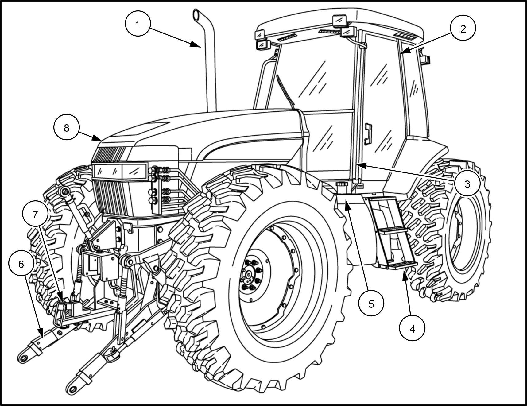
Left hand entry grab rail Engine - end drawbar
Left hand cab entry steps Engine hood
1 - GENERAL INFORMA TION
Suggest:
If the above button click is invalid.
Please download this document first, and then click the above link to download the complete manual.
Thank you so much for reading

RAIL13TR02345F A 2
Cab Battery box and cover
Right hand entry grab rail
Right hand cab entry steps
Engine hood Cab - end drawbar
Right hand fuel tank and fill Cab - end three point hitch

1 - GENERAL INFORMA TION
1 1
