
Chassisandcounterweight2
Jacking up the fork truck3
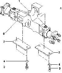
Chassis and counterweight
Chassis
The vehicle chassis is a welded construction with bolted on counterweight.
The fuel tank is arranged in the right chassis half and the hydraulic tank in the left chassis half..
Counterweight
The counterweight is fastened to the welded chassis construction with four bolts, see diagram.

1 - Hexagon bolt M24x130 / 8.8
Tightening torque = 710 Nm
2 - Spherical washer
3 - Cone pan
Weight of counterweight: 2407 kg
Jacking up the fork truck
ATTENTION Before jacking up the fork truck, apply the parking brake.
For various servicing routines, the fork truck must be jacked up.
When jacking up the fork truck, suitable measures must be taken to prevent the fork truck slipping or tilting, e.g. using wooden blocks.
Always ensure that only jacks with sufficient bearing capacity are used and that the fork truck is jacked up only on level ground and secured to prevent it rolling.
Only jack up the vehicle at the points shown in the photos, i.e. at the mast on the left or right and at the chassis at the front or rear.
Do not jack up the fork truck at the counterweight!
When jacking up the fork truck at the mast, the safety regulations for working on the mast must be observed.
Chassis and counterweight
Workshop manual 7084 - 86
Steering axle
Lubricant
bearings hub Wheel
litthium -20, DIN51825-KP2K to acc F Grease saponified
litthium -30, DIN51825-KP2K to acc F Grease saponified
bearings axle Sub lithium -20, DIN51825-KPF2N to acc FL Grease saponified
148659 No - Ident STILL
Design of the steering axle

The steering axle is mounted with 2 buffer elements on the counterweight. The stub axlesare supported in taper roller bearings in the axle body.Steer angle limitation takes place via stop bolts on the stub axle
1Axle body
2Fixing plates
3Hexagon bolt
4 Lockwasher 5Bufferelements
Removing the steering axle
CAUTION: Only remove the steering axle with the mast mounted! Risk of tilting!
-Apply the handbrake.
-Place wooden blocks under the front wheels to preventthevehiclerolling.

-Loosen the steering axle wheel nuts.
-Jack up the vehicle in the precribed manner. (SeeGroup01)


-Removethewheels.

-Unscrewthehydraulicconnectionsfromthesteering cylinder.
CAUTION: Hydraulicoilwilldischargewhenthe hydraulic connections are unscrewed. Collect hydraulic oilanddispose of ina proper manner.
-Place a hand pallet truck or similar with blocks of wood underthe steering axle.
-Unscrewthefourcheese-headscrewsforfixingthe steering axle.
Fitting the steering axle
- Fitting takes place in reverse orderto removal.
- Tightening torque of 4cheese-head screws: MA = 195 Nm

CAUTION: Do not interchange left and right hydraulicconnections!

Workshop manual 7084
Steering axle

Removing the wheel hub
5
7
8
9
10
11
12
-Loosen nuts(11)and removewheel.
-Removedustcap (7).
-Loosen hexagonnut (8).
-Removewasher(9)withpin (6).
-Removewheelhub.
-Removetaperrollerbearings(4)and(10)fromwheel hub; for this purpose, the radial seal (3) must be removed..
-If necessary, remove outer rings of taper roller bearings (4)and (10).Fitting the wheel hub
-Thoroughly grease sealing lips ofradial seal.
-FilltaperrollerbearingswithgreaseFbetweeninner ring and cage.
-Fill bearing spaces at the points marked (x) with grease F.
-Fitting takes place in reverse order to removal.
-Tighten hexagonnut(8)constantly turning the wheel hub.
Tightening torque: MA = 470 Nm
Checking the steer angle
The steer angle a must be 80° - 82°. To facilitate measurement, the supplementary angle b can be used. This must be 98° - 100°.
ATTENTION:It must be ensured that the steer angle is definitely limited by the stop bolts (1). The stop must not take place in the steering cylinder.
Adjusting the steer angle
The steer angle is limited by one stop bolt (1) on each side respectively.

-Adjustthe leftandrightsteerangles(1) to 80°-82° with the stop bolts (1).
-Check the opposite angle.
- Check the free space at full steering wheel lock.
-Checkthatthe steerangle stop doesnottakeplace in the steering cylinder.
turn right
turn left
steering angles
Workshop manual 7084 - 86
Steering axle

Removing the stub axle
1Hexagon bolt
2Washer
3Kingpin
4Plug
5Stub axle
6Hexagon bolt
7Hexagonnut
8Spacer
9Scraperring
10Taperrollerbearing
11Spacer
12Nipple
13Taperrollerbearing
14Scraperring
15O-ring
16Spacer
-Removewheel.
- Press out bolt between tie rod and stub axle.
- Loosen hexagon nut(1).
-Removewasher(2).
- Press out king pin (3) downwards.
- Remove stub axle from axle.
-Removespacers,O-ring,scraperrings,taper roller bearings and spacers (8 - 16)fromstub axle.
Fitting the stub axle
1 Hexagon nut
2 Washer
3 King pin
4 Plug
5 Stub axle
6 Spacer
7 Scraper ring
8 Taper roller bearing
9 Spacer
10 Taperrollerbearing
11 Scraper ring
12 O-ring
13 Spacer
14 Bolt
-Fit spacer (9) in stub axle.
-Fit both taperroller bearings (8+10). Grease both bearings well with grease FL!
-Thoroughly grease sealing lips of scraper rings (7+11) with grease FL
-Fit scraper rings (7+11), both spacers (13, 6 ) and O-ring(12).
-Fit sub axle in axle.
-Insert king pin (3) from below; lightly oil pin.
-Fit washer (2).
-Fit a new hexagon nut (1) and tighten with a torque of: MA = 310 Nm.
-Press in bolt (14) of tie rod and secure with pins.
-Fit wheel.
-Grease steering axle with grease FL. Greasing the steering axle
-Operate steering while greasing steering axle.
- Grease eight nipples of steering axle with grease FL until fresh grease discharges at the bearing points (see diagram on page 8)
Steering axle
Workshop manual 7084 - 86
Steering axle
Removing the tie rods
The steering axle has two tie rods seated between the steering cylinder and both stub axles.

1 Sub axle
2 Piston rod
3 Seals
4 Pins
5 Bolt
6 Tie rod
7 Ball socket
Removepins(4)
Press out bolt (5)
Fitting the tie rods
Fitting takesplace in reverse order to removal.
Bolt press-in force on cylinder side: max. 29 kN
Bolt press-in force on stub axle side: max. 38 kN
3 4 4 5
Removing the steering cylinder
-Remove tierods.
- Unscrew hydraulic connections and mark.
ATTENTION: Discharginghydraulic oil.
- Loosen fourbolts (1).
Fitting the steering cylinder
- Tighten bolts (1).
Tightening torque: MA= 295 Nm
- Screw on hydraulic connections.
ATTENTION:Donotinterchangehydrauliclines.
- Fit tie rods.
NOTE: Instructions for removing and fitting the steering cylinder are given under Group 06.
Greasing the steering axle
-Relievethesteeringaxlewhilstgreasingandoperate the steering.
- Grease the eight nipples (2) of the steering axle, starting from the upper nipples until fresh grease discharges atthe bearing points.
NOTE: When greasing the upper bearing, it is unnecessaryforgreaseto dischargefromthe upper seal. It can also deviate downwards.
Steering axle

Technicalservice data2
Geardrive3+4
Spurgearing withdifferential5
Fittingthegear drive6
Geardrive/tubularshaft7
Axle shaft8
Wheel hub9
Workshop manual 7084 - 86
Technical service data
03 Group drive ear G2 0 - 40 AE Type
torque ightening Tm N 1000 = MA axle Drive Chassis/
torque Tightening Nm 295 = MA Transmission housing/ Axle clearance Axial mm 06 0 - to mm 03 0 + shaft tubular Gear
torque Tightening 10.9 18 x M8 ZS hub Wheel flange/ Centering Nm 135 = MA
torque ightening Tm N 70 = MA plug drain Oil
torque Tightening Nm 120 = MA 9 10 35 x M12 ZS shaft Axle oil ransmission Te litr 5 9 = Capacity
type rease Ge additiv EP with grease soap Lithium
Gear drive Description
The gear drive consists of two-speed spur gearing withdifferential(1)anddoublesupporteddrivepinion aswell asflange-mounted d.c.motor(2),a long axle housing(3)andanaxlehousing(shortside) integrated in the transmission case (1).

Thelongaxlehousing(3)isboltedtothespurgearing. Both are bolted to the chassis and simultaneously serve for accommodating themastbearing.

Gear drive


1Transmissioncase
2
Spur gearing with differential

3Dowel pin
4Cheese-headscrew
5Taperrollerbearing
6Differential
7Gear
8Pin
9Hexagon bolt
10Washer 145 x 130 x 0.5 - 0.9
11Taperrollerbearing
12Gearwith shaft
13Washer 160 x 85 x 0.5 - 0.9
14Lock ring
15Reducingpipe
16Seal
17Plug
18Cover
19Plug
20Catch
21Shaft seal
22Taperrollerbearing
23Gear
24O-ring
25Washer 75 x 65 x 0.5 - 0.8
26O-ring
27Shaft seal
28Cover
29Lock washer
30Hexagon bolt M8 x 20 8.8
Thank you very much for your reading. Please Click Here. Then Get COMPLETE MANUAL.NOWAITING

NOTE:
If there is no response to click on the link above, please download the PDF document first and then clickonit.
Workshop manual 7084 - 86
Gear drive
Removing the gear drive
Removemast
Jackup vehicle
Drain oil (2) and collect
Loosenwheels/mounting
Removewheels
DisconnectE-motorcables (mark!)
Disconnect brake line at main brake cylinder
Removebrake linefromparking brake
Support gear drive with acraneorrope winch
Unscrew bolts (3) left and right
Fitting the gear drive
Position gear drive in chassis with a crane or rope winch

Drawgeardriveagainstchassiswith16boltsand16 washers
Tighten all bolts (3)
Tightenting torqueMA =1000Nm
Removecrane orropewinch
ConnectE-motorcables
Connect brake lines at main cylinder

Fit brake lines in parking brake
Fit wheels (see Group 04)
Mount mast (see Group 20)
Measure oil level with dipstick
Oil capacity: 9.5 litre
Transmission oil: SAE 90 EP - 51512
Gear drive/tubular shaft
Housing = B
Gear tubular shaft = A mm
Instructions for adjusting gear tubular shaft bearing
1. Measureboth taper rollerbearings complete on thegeartubularshaftuptothestopinthevertical positionAover outer rings.
2.Measurehousing mountingdimension B
3.Measure centring collar length C on cover
4.Packing thickness D=B-(A+C+0.06)
5.RoundpackingthicknessDupordownaccording to actual dimension = D + 0.03mm (initial tension)to 0.06mm(clearance).
Cover = C
6.Bothtaperrollerbearingsmustbefittedwith50% greasefilling. Transmission oilSAE140 EPcan be used as a substitute.
7.Prefittaperrollerbearing outer ring (tacho) with fitting mandrel about 20 mm.
8.Fit geartubularshaft.
9.Prefittaperrollerbearing outer ring (cover) with fitting mandrel about 20 mm.
10.Insertpackingandbringtaperrollerbearingouter ring into its final position by evenly tightening the bolts.