
FARMALL® 55A FARMALL® 65A FARMALL® 75A Tractor Part number 51489994 1st edition OctoberEnglish2018 SERVICE MANUAL
Contents Maintenance . . . . . . . . . . . . . . . . . . . . . . . . . . . . . . . . . . . . . . . . . . . . . . . . . . . . . . . . . . . . . . . . . . . . . . . . . . . . . . New unit operations [00.150] Start-up . . . . . . . . . . . . . . . . . . . . . . . . . . . . . . . . . . . . . . . . . . . . . . . . . . . . . . . . . . . . . . . . . . . . . . . . . . . . . 00.2 Engine . . . . . . . . . . . . . . . . . . . . . . . . . . . . . . . . . . . . . . . . . . . . . . . . . . . . . . . . . . . . . . . . . . . . . . . . . . . . . . . . . . . . . . . [10.001]Engineand crankcase . . . . . . . . . . . . . . . . . . . . . . . . . . . . . . . . . . . . . . . . . . . . . . . . . . . . . . . . . . . . . 10.1 Clutch . . . . . . . . . . . . . . . . . . . . . . . . . . . . . . . . . . . . . . . . . . . . . . . . . . . . . . . . . . . . . . . . . . . . . . . . . . . . . . . . . . . . . . . [18.110] Clutchand components . . . . . . . . . . . . . . . . . . . . . . . . . . . . . . . . . . . . . . . . . . . . . . . . . . . . . . . . . . . . 18.1 T ransmission . . . . . . . . . . . . . . . . . . . . . . . . . . . . . . . . . . . . . . . . . . . . . . . . . . . . . . . . . . . . . . . . . . . . . . . . . . . . . . 14] Mechanical transmission 12] Power shuttle transmission Four-Wheel Drive (4WD) system . . . . . . . . . . . . . . . . . . . . . . . . . . . . . . . . . . . . . . . . . . . . . . . . . . Mechanicalcontrol Drive (4WD) gearbox Frontaxle system . . . . . . . . . . . . . . . . . . . . . . . . . . . . . . . . . . . . . . . . . . . . . . . . . . . . . . . . . . . . . . . . . . . . . . . [25.100] Poweredfront axle . . . . . . . . . . . . . . . . . . . . . . . . . . . . . . . . . . . . . . . . . . . . . . . . . . . . . . . . . . . . . . . . . 25.1 Rearaxle system . . . . . . . . . . . . . . . . . . . . . . . . . . . . . . . . . . . . . . . . . . . . . . . . . . . . . . . . . . . . . . . . . . . . . . . . Powered rear axle Power T f (PT Rear mechanicalcontrol Rear control 14]T rear Power T f (PT Brakesand controls . . . . . . . . . . . . . . . . . . . . . . . . . . . . . . . . . . . . . . . . . . . . . . . . . . . . . . . . . . . . . . . . . . . . Hydraulicservice brakes Hydraulicsystems Hydraulicsystems 51489994 09/10/2018
16] hitch cylinder Remote control valves Steering . . . . . . . . . . . . . . . . . . . . . . . . . . . . . . . . . . . . . . . . . . . . . . . . . . . . . . . . . . . . . . . . . . . . . . . . . . . . . . . . . . . . . [41.101] Steering control . . . . . . . . . . . . . . . . . . . . . . . . . . . . . . . . . . . . . . . . . . . . . . . . . . . . . . . . . . . . . . . . . . . . 41.1 [41.200] Hydrauliccontrol components . . . . . . . . . . . . . . . . . . . . . . . . . . . . . . . . . . . . . . . . . . . . . . . . . . . . . . 41.2 [41.216] Cylinders . . . . . . . . . . . . . . . . . . . . . . . . . . . . . . . . . . . . . . . . . . . . . . . . . . . . . . . . . . . . . . . . . . . . . . . . . . . 41.3 Cab climate control . . . . . . . . . . . . . . . . . . . . . . . . . . . . . . . . . . . . . . . . . . . . . . . . . . . . . . . . . . . . . . . . . . . . . [50.100] Heating . . . . . . . . . . . . . . . . . . . . . . . . . . . . . . . . . . . . . . . . . . . . . . . . . . . . . . . . . . . . . . . . . . . . . . . . . . . . . 50.1 [50.200] Air conditioning . . . . . . . . . . . . . . . . . . . . . . . . . . . . . . . . . . . . . . . . . . . . . . . . . . . . . . . . . . . . . . . . . . . . . 50.2 Electricalsystems . . . . . . . . . . . . . . . . . . . . . . . . . . . . . . . . . . . . . . . . . . . . . . . . . . . . . . . . . . . . . . . . . . . . . . . Electricalsystem Cab V and (HV AC) controls Harnesses and connectors Engine starting system Alternator [55.302]Battery . . . . . . . . . . . . . . . . . . . . . . . . . . . . . . . . . . . . . . . . . . . . . . . . . . . . . . . . . . . . . . . . . . . . . . . . . . . . . . 55.6 [55.408] W arning indicators,alarms, and instruments . . . . . . . . . . . . . . . . . . . . . . . . . . . . . . . . . . . . . . 55.7 Cab controls F AUL T CODES Front loaderand bucket . . . . . . . . . . . . . . . . . . . . . . . . . . . . . . . . . . . . . . . . . . . . . . . . . . . . . . . . . . . . . . . [82.100] Arm . . . . . . . . . . . . . . . . . . . . . . . . . . . . . . . . . . . . . . . . . . . . . . . . . . . . . . . . . . . . . . . . . . . . . . . . . . . . . . . . . 82.1 Bucket Front loaderand bucket generic Platform, cab, bodywork, and decals . . . . . . . . . . . . . . . . . . . . . . . . . . . . . . . . . . . . . . . . . . . . . [90.150] Cab . . . . . . . . . . . . . . . . . . . . . . . . . . . . . . . . . . . . . . . . . . . . . . . . . . . . . . . . . . . . . . . . . . . . . . . . . . . . . . . . . 90.1 51489994 09/10/2018
SER VICE MANUAL Engine
F ARMALL 55A F ARMALL 65A F ARMALL 75A 51489994 09/10/2018

A TTENTION: Use appropriate equipmenthold and lift heavy Makesure that thatthe bodyand partsare safely supportedsafely ropesand Makesure that one close whenyou lift heavy
ANIL17TRO0925AA 1
T o access the remove the protectivecovers (1) either Remove the cover retainingbolts(2) and remove the side
Use the A / C device (1) discharge the gas the tem. For this, use the A / C device pressurehose (red) and connectthe compressor ’ s red Connect the blue hose the compressor ’ s blue
Engine Engineand crankcase
A TTENTION: Use appropriate tools align holes NEVERUSE YOUR FINGERS HANDS Follow these
Engineand crankcase - Disassemble
ENGINE – Removal


ANIL17TRO0926AA 2
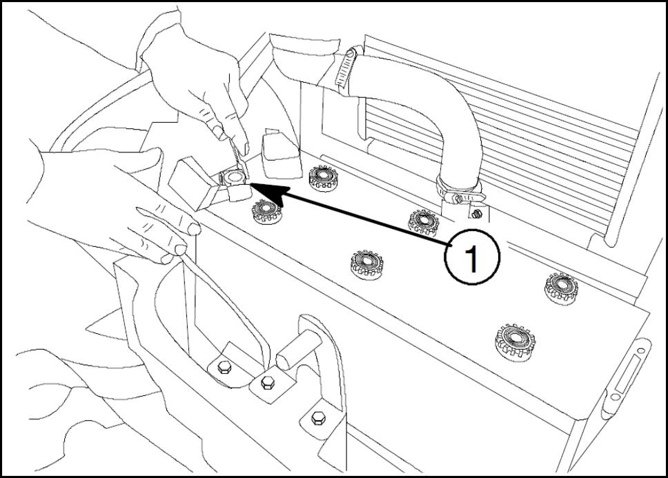
Disconnect the battery terminals (1) .
ANIL17TRO0927AA 3 51489994 09/10/2018 10.1 [10.001] / 4
5
6
ANIL18TRO1093AA
Engage the
ANIL18TRO1092AA
Remove the front weight connection rod (1)
ANIL17TRO0992AA
Remove the front weightlower connection rod (1)

Engine Engineand crankcase


ANIL17TRO0930AA 7 51489994 09/10/2018 10.1 [10.001] / 5
4
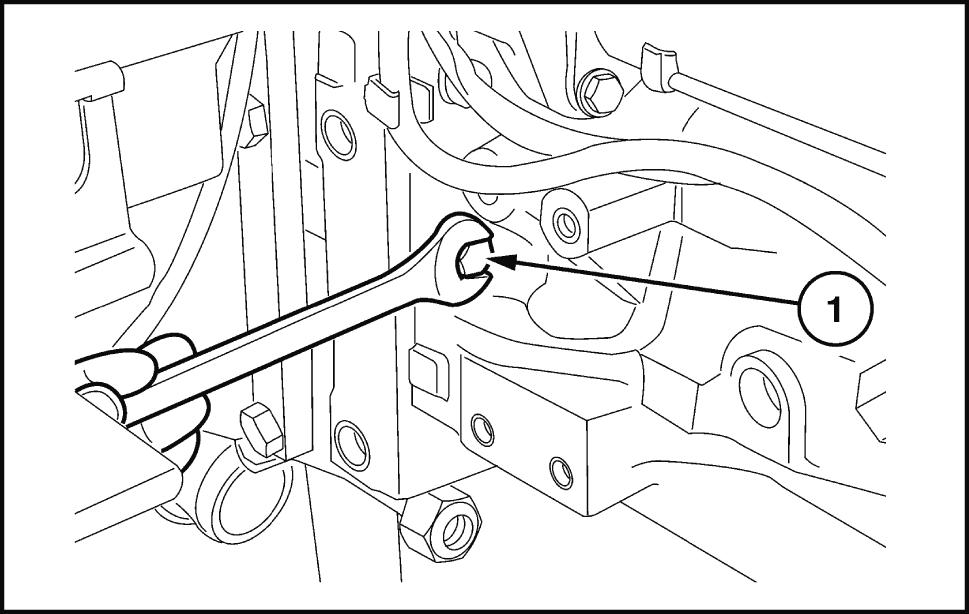
Remove the engine oil drain plug (1) both
Disconnect lines(1) and (2) the cab A / C and heating (if
Engine Engineand crankcase


MOIL13TR02884AA 51489994 09/10/2018 10.1 [10.001] / 6
Remove the front weights (1) . (1) Use the specifictool discharge the refrigerant from the system via the greasers and (2) . Remove the bracketstripsand separate the two 380000315

ANIL17TRO0931AA 8
ANIL1800789AA 9
Remove the front centerand rear retainingbolts the front wheeldrive controlshaft Then remove the (1)

MOIL13TR02886AB 1 1
WLAPL4S10C1 10A
1 Lift the rear the tractorwitha hydraulic Place a mechanical jack underthe crawl speedgear housing. Use air gun remove the retainingnuts the left rear Then remove the
10. Separate the supplyand return pipesfor the (1) mission cooling oil the connection Disconnect the hosesfrom the supportsthe engine


WLAPL4S10C1 13AA 51489994 09/10/2018 10.1 [10.001] / 7
Engine Engineand crankcase
WLAPL4S10C1 12AA
Remove the retaining ring (2) Movethe front screen the directionthe arrow(1) remove the screen from the groovesthe front axle.
MOIL13TR02887AB
17. Disconnect all electrical connections that prevent the enginefrom being removed from the gearboxtransmission For the main connections (1) , the maincab and power connections (2) , the gine controlunit connections (3) , the fuse box (4) , the sensors, and the extensions,depending the tractor

Engine Engineand crankcase

14. Remove the retainingbolts the middle bracket the drive shaft(1) Remove the shaftand the Remove the adjustmentwasherthat adjusts the shaft space


WLAPL4S10C1 15AA
ANIL18TRO1094AA
Loosen the Separate the suctionhose(1) that goes the oil filter from the transmission (2)
For machines with a hydrauliclifter and middle mounted remove the oil feed pipe the distributor the lifting deviceand oil filter(1)
MOIL13TR02889AB 51489994 09/10/2018 10.1 [10.001] / 8
Engine Engineand crankcase


Loosen the strip the inlet the hose(1) that feeds fluid the radiator Disconnect the Drainthe engine radiatorfluid and refill with fluid.
MOIL13TR02942AA
Remove the retaining Hose(2) that returns the radiatorfluid the
Loosen the Disconnect the hose(1) that runs from the air filter the remove the two bolts(3) and remove the bracket (2) .
MOIL13TR02890AB 51489994 09/10/2018 10.1 [10.001] / 9
18. Remove the retainingbolts(1) . Remove the top diator guard(2) Remove all the remaining free wire
ANIL18TRO1099AA
MOIL13TR02891AB
Attach chains ropes the liftingand eye bolts hind the engineand attach a Place a fixed liftingjack (2) underthe clutch body(1) next the gine retainingflange.Applythe handbrake.
MOIL13TR02881AB
Disconnect the hydraulic steeringhoses(1) nectthe lines from the axle bracket. .
22. Loosen the strip (1) . Remove the hose(2) that nectsthe air filter the injection
ANIL1898734AA
WLAPL4S10C129A 51489994 09/10/2018 10.1 [10.001] /
Engine Engineand crankcase

Unplug the headlamp and the signal cable bundle from the enginehood socket (1)


Separate the enginefrom the transmission with tool 380000405 (2) . 380000405 .
Engine Engineand crankcase
WLAPL4S10C140A
Remove the retainingbolts(1) between the engine and the
Placethe fixed lifting jack (1) underthe additional weight Use woodenblocks (2) secure the front
WLAPL4S10C132AA 51489994 09/10/2018 10.1 [10.001] / 1 1
WLAPL4S10C131AA
WLAPL4S10C130A
26. Placethe moving tractor separator tool (2) underthe enginewith the mounting bracketand the adapter Place a woodenblock(1) the points tact between the tool and the motor Chockthe axle prevent the axle from 380000405 .


WLAPL4S10C136A
Checkthat there elbow between the engineand the radiator . Separate the engine (2) from the axle (3) T o prevent damagethe fins the radiator the engine ventilator (1) try avoid incorrect manoeuvres with the Lower the engine (2) onto a support


Remove the bolts that secure the front axle bracket the engine (2)
Engine Engineand crankcase

WLAPL4S10C133A
Loosen the four bolts(1) Remove the fan (2)
MOIL13TR02885AA 51489994 09/10/2018 10.1 [10.001] /
WLAPL4S10C138A
30. Place a woodenstop betweenparts(3) and (1) . Place a fixed liftingjack (3) underthe front axle drive groove (1)
Withthe connectionassemblyfirmly place a lifting jack the rear the engine leave slack the Adda rope chain the front the engine (1) . Keepthe engine balanced and take the slackout the lifting assembly

Engineand crankcase - Install
Repeat this operation reposition the compressor and the corresponding
Engine Engineand crankcase
Reattach the flexiblestrap the alternator and takethe tension according the procedure the Alternator T ension adjust
Put the compressor the bracket together with the relevanthose Securewith the Use tool 38020001 1 installthe multi V (1) The drive bracketthe compressor clutch actuator (2) Outeredge the multi V belt pulley (3)T ool space.Use drivethe tool. The bracket (1) housedthis space (4) T ail The multi V belt drivesthe pulley (5) This space around the outer edge(2) allowsthe tool remain connected the compressor (2) .
WLAPL4S10C101C 1 51489994 09/10/2018 10.1 [10.001] /

WLAPL4S10C142A
Remove the three bolts(1) . Remove the corresponding dust coverfor the compressor 2
With yourleft hand the ventilator and your right hand the turn both clockwisemovethe belt along the compressor pulley Replace the dust cap the compressorclutch. T o prevent loosening,make sure that locking film covers the endsand tighten the three


Position the ventilator (2) (1) T ightenthe four screws the correct torque value.
Makesure thatthe multi V belt(2) properly positioned the ventilatorpulley
MOIL13TR02885AA 5 51489994 09/10/2018 10.1 [10.001] /
Engine Engineand crankcase
Movethe belt (2) the side the compressor ley tool 38020001 1 underthe Hookthe pressorclutchfrom the innermost part the tool slightly stretch the
Position the alternator (1) and elasticbelt (3) T ighten the belt tensioner (2)

WLAPL4S10C143A 3
WLAPL4S10C145A 4
Then combine the two components with the special adjustmentboltsand the necessary adjustment ers the sump / cylinderblock
Placethe three hooks the chain the holes the Usea winch lift the engine completely from the platform
Remove the fixed lifting jack (3) and the wooden wedge(2) previously positionedunderthe groove bracketthe front axle drive shaft(1) (2)
WLAPL4S10C133A 9 51489994 09/10/2018 10.1 [10.001] /
With a position the engine (1) the tool (2) Remove the bolts attached previously the rear the engine for the purposes
Engine Engineand crankcase
1 Reposition the movingtool underthe engine semble the tractors (2) a woodenblock between the contactpoints the tool(1) and
10. Position the engine (2) the front axle.(3) . T o vent damagethe fins the radiatorthe engine ventilator , try avoid incorrect manoeuvres with the (1)
WLAPL4S10C140A 7
WLAPL4S10C131AA 8
WLAPL4S10C138A 6
WLAPL4S10C130A 1 1 51489994 09/10/2018 10.1 [10.001] /
WLAPL4S10C132AA
16. Apply L OCTITE ® 518™ and sealantthe matching surfacesthe motorand the clutch
Remove the sealantfrom the two surfacesthe gine and
18. The assemblyphase describedhere requires the presencetwo three workersuse the special movingtool needed dismantle the tractor , and movethe engine / front axle housing towards the gearbox
14. Remove the fixed liftingjack (1) previouslyplaced der the additionalweight Remove the chocks (2) that secure the front (2)
Whenyou mount the engine / front axle assembly the gearbox pushthe front wheels prevent the hosesand the cables / electrical connections being trapped between the two this phaseyou also need turn the crankshaft with the radiator cooling fan help establish a connectionbetween the sleeve and the drive
Place a woodenchock underthe right rear Makesure thatthe handbrake fully appliedand that all fixed and movablestandsare securely
Engine Engineand crankcase
T ighten all the retainingbolts(1) that connect the gine the gearbox housing connect the two semblies. (1)
MOIL13TR02889AB
WLAPL4S10C129A
Reinstall the support bracket (2) the cab connectors (1) , the cab and the cup filter(3) Connect the mechanicaldiesel automator connection the sediment filter the cup filter .
Reattach the starter motor(2) Then connect the engine chassiscableand battery Secure the chassiscablewith the bolt (3) the right hand reconnect the positive battery cableand wiring harnessthe starter motorand ternatorPut the cover(1) back ontothe starter motor (2)

23. Connect the cab electricalcable connector (1) the left Put the connector the maxifuse box and fastenwith the cuf
Lay the FPT enginecable the Reconnect the various connections.Secure the cableswith the cuf
WLAPL4S10C135A 51489994 09/10/2018 10.1 [10.001] /
Reconnect the main electrical connections (1) , the cab connections and power(2) , the engine controlunit connections (3) , the fuse section (4) and the sensors, and the extensions,depending the tractor

Engine Engineand crankcase
21. Remove the winch chains. Remove the lifting jack (1) previously positionedunderthe clutch housing (2) Remove the movingtool used disassemble the
WLAPL4S10C139A
Thank you very much for your reading. Please Click Here. Then Get COMPLETE IfNOTE:MANUAL.NOWAITINGthereisnoresponse to click on the link above, please download the PDF document first and then clickonit.

MOIL13TR02891AB
Connect the hose(2) that connects the air filter the injection T ightenthe strip secure the (1) .
MOIL13TR02890AB 51489994 09/10/2018 10.1 [10.001] /
Installand connect the hydraulicsteering (1) Secure the hydraulicsteeringlines the front axle bracket.
MOIL13TR02881AB
27. Reinstall the two feed and return pipes the cab heater (1) and the hose(3) from the expansion which attachedthe bottom

Connect the hose that runs from the air filter the T ightenthe strip secure the (1)
Engine Engineand crankcase
MOIL13TR01739AB
Also reattach the hood bracket (2) T ightenthe two bolts(3) secure the hood bracket.
MOIL13TR02888AB 51489994 09/10/2018 10.1 [10.001] /
32. Attachthe top radiatorguard(2) . Makesure tion the electricalwiring bundles and hoses correctly the slots between the shieldand the radiator T ighten the three radiatorguard bolts(1)
31. Installthe hose(1) that supplies radiatorfluid the radiator T ightenthe strip secure the
ANIL18TRO1099AA
Engine Engineand crankcase


MOIL13TR02942AA
Install the transmission oil filter(2) machines with a hydrauliclifter and middle mountedvalves, connect and secure the oil feed hose the distributor the lifting deviceand the middle mountedvalves (1) , any , the connection point(3)
34. Connect the transmission oil feed hose(1) the filter (2) Use the strips secure the feed
36. Reattach the drive shaftwithits center bracket (1) and retaining Install the adjustmentwasher Adjust the shaft


WLAPL4S10C1 15AA 51489994 09/10/2018 10.1 [10.001] /
ANIL18TRO1093AA
Engine Engineand crankcase
MOIL13TR02887AB
Reinstall the transmission oil drain plug (1) both side. Usea pump refillthe oil.
ANIL18TRO1092AA
Use the defined controlunit 380000315 fill the A / C systemwith coolantgas.
37. Reinstall the front axle control shaft guard(1) . T ightenthe center , and rear retaining

Usea hydraulic jack lift the rear the tractor movethe mechanical lifting jack from underthe left crawl speedgear Lower the wheelsontothe Use air gun tighten the retainingbolts.
Connect and securelines(1) and (2) the cab A / C and heater systems (if any).
WLAPL4S10C1 12AA
WLAPL4S10C1 10A
Engine Engineand crankcase
Reconnect the air conditioner lines(1) and (2) the compressorSecure the lines with cuf and
MOIL13TR02884AA
WLAPL4S10C106AA 51489994 09/10/2018 10.1 [10.001] /