
Copyright © 2014 CNH Industrial America LLC. All Rights Reserved. Part number 47795177 1st edition NovemberEnglish2014 SERVICE MANUAL AXIAL-FLOW® 5140 AXIAL-FLOW® 6140 AXIAL-FLOW® 7140 Tier 4B (final) Combine
SER VICE MANUAL AXIAL-FLOW® 5140 [YEG012701 - ] AXIAL-FLOW® 6140 [YEG012701 - ] AXIAL-FLOW® 7140 [YEG012701 - ] 47795177 16/1 1/2014

Contents INTRODUCTION Engine . . . . . . . . . . . . . . . . . . . . . . . . . . . . . . . . . . . . . . . . . . . . . . . . . . . . . . . . . . . . . . . . . . . . . . . . . . . . . . . . . . . . . . . [10.001]Engineand crankcase . . . . . . . . . . . . . . . . . . . . . . . . . . . . . . . . . . . . . . . . . . . . . . . . . . . . . . . . . . . . . 10.1 [10.202] Air cleaners and lines . . . . . . . . . . . . . . . . . . . . . . . . . . . . . . . . . . . . . . . . . . . . . . . . . . . . . . . . . . . . . . 10.2 [10.216]Fuel tanks . . . . . . . . . . . . . . . . . . . . . . . . . . . . . . . . . . . . . . . . . . . . . . . . . . . . . . . . . . . . . . . . . . . . . . . . . . 10.3 [10.254]Intakeand exhaust manifolds and muffler . . . . . . . . . . . . . . . . . . . . . . . . . . . . . . . . . . . . . . . . . 10.4 [10.310] Aftercooler . . . . . . . . . . . . . . . . . . . . . . . . . . . . . . . . . . . . . . . . . . . . . . . . . . . . . . . . . . . . . . . . . . . . . . . . . . 10.5 Engine cooling system [10.408] Oil coolerand lines . . . . . . . . . . . . . . . . . . . . . . . . . . . . . . . . . . . . . . . . . . . . . . . . . . . . . . . . . . . . . . . . . 10.7 Fan and drive Stationary air screen Main gearbox and drive . . . . . . . . . . . . . . . . . . . . . . . . . . . . . . . . . . . . . . . . . . . . . . . . . . . . . . . . . . . . . . . [14.100]Main gearbox and drive . . . . . . . . . . . . . . . . . . . . . . . . . . . . . . . . . . . . . . . . . . . . . . . . . . . . . . . . . . . . 14.1 T ransmission . . . . . . . . . . . . . . . . . . . . . . . . . . . . . . . . . . . . . . . . . . . . . . . . . . . . . . . . . . . . . . . . . . . . . . . . . . . . . . [21.114] Mechanical transmission . . . . . . . . . . . . . . . . . . . . . . . . . . . . . . . . . . . . . . . . . . . . . . . . . . . . . . . . . . . 21.1 [21.145] Gearbox internal components . . . . . . . . . . . . . . . . . . . . . . . . . . . . . . . . . . . . . . . . . . . . . . . . . . . . . . 21.2 [21.182] Dif ferential . . . . . . . . . . . . . . . . . . . . . . . . . . . . . . . . . . . . . . . . . . . . . . . . . . . . . . . . . . . . . . . . . . . . . . . . . . 21.3 Frontaxle system . . . . . . . . . . . . . . . . . . . . . . . . . . . . . . . . . . . . . . . . . . . . . . . . . . . . . . . . . . . . . . . . . . . . . . . [25.310]Final drives . . . . . . . . . . . . . . . . . . . . . . . . . . . . . . . . . . . . . . . . . . . . . . . . . . . . . . . . . . . . . . . . . . . . . . . . . 25.1 Rearaxle system . . . . . . . . . . . . . . . . . . . . . . . . . . . . . . . . . . . . . . . . . . . . . . . . . . . . . . . . . . . . . . . . . . . . . . . . Powered rear axle Final drive steering and shafts Hydrostatic drive . . . . . . . . . . . . . . . . . . . . . . . . . . . . . . . . . . . . . . . . . . . . . . . . . . . . . . . . . . . . . . . . . . . . . . . . . [29.100] T ransmission and steering hydrostaticcontrol . . . . . . . . . . . . . . . . . . . . . . . . . . . . . . . . . . . . . 29.1 [29.134] T assembly . . . . . . . . . . . . . . . . . . . . . . . . . . . . . . . . . . . . . . . . . . . . . . . . . . . . . . . . . . . . . . . 29.2 [29.202] Hydrostatic transmission . . . . . . . . . . . . . . . . . . . . . . . . . . . . . . . . . . . . . . . . . . . . . . . . . . . . . . . . . . . 29.3 47795177 16/1 1/2014
Reservoir , cooler , and lines Pumpand motor components Rear hydrostatic transmission Brakesand controls [33.110] Parkingbrake parkinglock . . . . . . . . . . . . . . . . . . . . . . . . . . . . . . . . . . . . . . . . . . . . . . . . . . . . . . 33.1 [33.202] Hydraulicservice brakes . . . . . . . . . . . . . . . . . . . . . . . . . . . . . . . . . . . . . . . . . . . . . . . . . . . . . . . . . . . 33.2 Hydraulicsystems . . . . . . . . . . . . . . . . . . . . . . . . . . . . . . . . . . . . . . . . . . . . . . . . . . . . . . . . . . . . . . . . . . . . . . . Hydraulicsystems Pump control valves V ariable displacement pump [35.220] Auxiliary hydraulicpumpand lines . . . . . . . . . . . . . . . . . . . . . . . . . . . . . . . . . . . . . . . . . . . . . . . . . 35.4 Reservoir , cooler , and filters [35.359]Main controlvalve . . . . . . . . . . . . . . . . . . . . . . . . . . . . . . . . . . . . . . . . . . . . . . . . . . . . . . . . . . . . . . . . . . 35.6 [35.410] Header attachmentheight system . . . . . . . . . . . . . . . . . . . . . . . . . . . . . . . . . . . . . . . . . . . . . . 35.7 [35.536]Crop processorsystem . . . . . . . . . . . . . . . . . . . . . . . . . . . . . . . . . . . . . . . . . . . . . . . . . . . . . . . . . . . . 35.8 Steering . . . . . . . . . . . . . . . . . . . . . . . . . . . . . . . . . . . . . . . . . . . . . . . . . . . . . . . . . . . . . . . . . . . . . . . . . . . . . . . . . . . . . Steering control T rods Hydrauliccontrol components Pump Wheels . . . . . . . . . . . . . . . . . . . . . . . . . . . . . . . . . . . . . . . . . . . . . . . . . . . . . . . . . . . . . . . . . . . . . . . . . . . . . . . . . . . . . . [44.51 Front wheels . . . . . . . . . . . . . . . . . . . . . . . . . . . . . . . . . . . . . . . . . . . . . . . . . . . . . . . . . . . . . . . . . . . . . . . . 44.1 Cab climate control . . . . . . . . . . . . . . . . . . . . . . . . . . . . . . . . . . . . . . . . . . . . . . . . . . . . . . . . . . . . . . . . . . . . . Heating V entilation Air conditioning Electricalsystems . . . . . . . . . . . . . . . . . . . . . . . . . . . . . . . . . . . . . . . . . . . . . . . . . . . . . . . . . . . . . . . . . . . . . . . [55.000] Electricalsystem . . . . . . . . . . . . . . . . . . . . . . . . . . . . . . . . . . . . . . . . . . . . . . . . . . . . . . . . . . . . . . . . . . . 55.1 47795177 16/1 1/2014
Engine intakeand exhaustsystem Harnesses and connectors Engine starting system Cold startaid Alternator Battery W arning and instruments Feeding control system Cab controls Groundspeed control 1 Electronicmodules Precisionfarming system Selective Catalytic Reduction(SCR) electricalsystem F AUL T CODES Attachments/Headers . . . . . . . . . . . . . . . . . . . . . . . . . . . . . . . . . . . . . . . . . . . . . . . . . . . . . . . . . . . . . . . . . . Attachment/Header reel control system Product feeding [60.105] Floatingroll, feed chain,and drive . . . . . . . . . . . . . . . . . . . . . . . . . . . . . . . . . . . . . . . . . . . . . . . . . 60.1 [60.110] Feeder housing . . . . . . . . . . . . . . . . . . . . . . . . . . . . . . . . . . . . . . . . . . . . . . . . . . . . . . . . . . . . . . . . . . . . . 60.2 [60.150]Feederdrive system . . . . . . . . . . . . . . . . . . . . . . . . . . . . . . . . . . . . . . . . . . . . . . . . . . . . . . . . . . . . . . . 60.3 [60.500] Gearbox housing . . . . . . . . . . . . . . . . . . . . . . . . . . . . . . . . . . . . . . . . . . . . . . . . . . . . . . . . . . . . . . . . . . . 60.4 Threshing . . . . . . . . . . . . . . . . . . . . . . . . . . . . . . . . . . . . . . . . . . . . . . . . . . . . . . . . . . . . . . . . . . . . . . . . . . . . . . . . . . Concave 10] Concavecontrol system Threshing mechanism drive system Rotor Separation . . . . . . . . . . . . . . . . . . . . . . . . . . . . . . . . . . . . . . . . . . . . . . . . . . . . . . . . . . . . . . . . . . . . . . . . . . . . . . . . . [72.410]Rotary separator drive system . . . . . . . . . . . . . . . . . . . . . . . . . . . . . . . . . . . . . . . . . . . . . . . . . . . . . 72.1 47795177 16/1 1/2014
Rotary separator Residue handling . . . . . . . . . . . . . . . . . . . . . . . . . . . . . . . . . . . . . . . . . . . . . . . . . . . . . . . . . . . . . . . . . . . . . . . . [73.210]Straw chopperdrive system . . . . . . . . . . . . . . . . . . . . . . . . . . . . . . . . . . . . . . . . . . . . . . . . . . . . . . . . 73.1 Straw chopper Chaf f spreader Cleaning . . . . . . . . . . . . . . . . . . . . . . . . . . . . . . . . . . . . . . . . . . . . . . . . . . . . . . . . . . . . . . . . . . . . . . . . . . . . . . . . . . . . Cleaning [74.101] Cleaningdrive systems . . . . . . . . . . . . . . . . . . . . . . . . . . . . . . . . . . . . . . . . . . . . . . . . . . . . . . . . . . . . 74.2 [74.114] Upper shakershoe . . . . . . . . . . . . . . . . . . . . . . . . . . . . . . . . . . . . . . . . . . . . . . . . . . . . . . . . . . . . . . . . . 74.3 18] Lower shakershoe Fan housing T ailings return system Crop storage / Unloading . . . . . . . . . . . . . . . . . . . . . . . . . . . . . . . . . . . . . . . . . . . . . . . . . . . . . . . . . . . . . [80.101]Clean grain elevator . . . . . . . . . . . . . . . . . . . . . . . . . . . . . . . . . . . . . . . . . . . . . . . . . . . . . . . . . . . . . . . . 80.1 Graintank Graintank unloaddrive system Graintank unload Platform, cab, bodywork, and decals . . . . . . . . . . . . . . . . . . . . . . . . . . . . . . . . . . . . . . . . . . . . . [90.100]Enginehoodand panels . . . . . . . . . . . . . . . . . . . . . . . . . . . . . . . . . . . . . . . . . . . . . . . . . . . . . . . . . . . 90.1 [90.105] Machineshieldsand guards . . . . . . . . . . . . . . . . . . . . . . . . . . . . . . . . . . . . . . . . . . . . . . . . . . . . . . . 90.2 [90.124] operatorseat . . . . . . . . . . . . . . . . . . . . . . . . . . . . . . . . . . . . . . . . . . . . . . 90.3 [90.150] Cab . . . . . . . . . . . . . . . . . . . . . . . . . . . . . . . . . . . . . . . . . . . . . . . . . . . . . . . . . . . . . . . . . . . . . . . . . . . . . . . . . 90.4 [90.151] Cab interior . . . . . . . . . . . . . . . . . . . . . . . . . . . . . . . . . . . . . . . . . . . . . . . . . . . . . . . . . . . . . . . . . . . . . . . . . 90.5 47795177 16/1 1/2014
47795177 16/1 1/2014 1
INTRODUCTION
• A void the use cans other inappropriatepressurized fuel delivery systems fill Such delivery systems may cause considerable
Batteries are made lead platesanda sulfuricacid solution. Because batteriescontainheavy metalssuch lead, CONAMA Resolution 401 / 2008 requires you return all used batteriesthe battery dealerwhenyou replaceany not dispose batteriesyour household Points sale are obliged to:
AXIAL FLOW®6140
• Modern oils contain not burn contaminated fuelsand wasteoils ordinary heating
Battery recycling
• The air conditioningsystem containsgasesthat shouldnot released into the Consultair tioning specialistuse a special extractor recharge the system properly
AXIAL FLOW®7140
air , and water quality important for all industries and life
When legislationdoesnot yet rule the treatmentsome the substances that advanced technology sound judgmentshould govern the use and disposal products a chemical and petrochemical
Helpfulhints
Familiarizeyourself with the relative legislation applicableyour country , and make sure that you understand this Where legislation obtain information from suppliers anti cleaning agents,etc., with regard the fect these substancesman and natureand how safely store,use, and dispose these
• avoidskin contactwith all Most these productscontain substances that may harmful your
AXIAL FLOW®5140
• Repairany leaks defectsthe engine cooling system hydraulicsystem immediately
Batteries and electric accumulatorscontain several substances that can have a harmful fect the environment the batteries are not properly recycledafter Improper disposal batteries can contaminate the groundwater , and CASE strongly recommends that you return all used batteries a CASE dealer , who will disposethe used batteries recycle the used batteries properly some this a legal
Mandatorybattery recycling
• not increase the pressure a pressurizedcircuit this may lead a component
• A void spillagewhenyou drain fluids such used engine coolant engine hydraulic brake etc. not mix drainedbrake fluids fuels with lubricants.Storeall drainedfluids safelyuntilyou can dispose the fluids a properway that complies with all local legislation and available
INTRODUCTION
Safetyrules - Ecology and the environment

NOTE:The following requirements are mandatory
• Protecthoses during Penetrating weld splattermay burn a hole weaken allowing the loss
• Accept the return your used batteries
• not allow coolant mixturesget into the Collectand dispose coolant mixtures properly
• Storethe returned batteries a suitable location
• Sendthe returned batteriesthe battery manufacturer for recycling
47795177 16/1 1/2014 4
the attachment machineshould become obstructed plugged; set the parking shut f the engine and remove the key , engage the transmissionwaitfor all machine attachmentmotion come a before leaving the operatorsplatform removing the obstruction
Keepall guardsand safety devices
Neverallow anyone climb the machine while the machine equipped with InstructorsSeat,this must only usedfor training Passengersmustnot alloweduse the Instructors
• Shut f the engineand remove the key
47795177 16/1 1/2014 5
Remember: A careful operatorthe best insuranceagainst Extremecare should taken keepinghandsand clothingawayfrom moving
Safetyrules - Personalsafety
AXIAL FLOW®7140
• Disengage all clutchinglevers
Keepall shields place. Neverwork around the machineany the attachments while wearingloose clothing that might catch moving
• Lower the attachment, equipped, the ground raisethe attachment completely and engage the cylinder safety Completing these actionswill prevent the attachment from lowering unexpectedly
Be sureall peopleand pets are clear the machinebefore Soundthe three times before starting
• Engage the parking
Alwayskeepthe machine gear while travelling The machineshould always equipped with suf ficientfront rear axle weight for safe Undersomefield more weightmay requiredthe front rear axle for adequatestabilityThis especially importantwhen operatinghilly conditions / when using heavy
Practicesafety365 days a year
AXIAL FLOW®6140
1 Never disconnectmakeany adjustments the hydraulicsystem unless the machine and / the attachment loweredthe groundthe safety lock(s) the engaged
Alwayslowerthe attachment, shut f the engine, set the parking brake, engage the transmissiongears, remove the key and waitfor all machine movementstop before leaving the operators
Keepall your equipmentsafe operating
When transporting a road highway , use accessorylightsand devices for adequatewarningthe operators other this check local government V arious safety lightsand devices are available from your CASE dealer
• Wait for all machine movementstop before leaving the operators
Carefullystudy these precautions, and those includedthe external attachmentoperators manual, and insistthat they followed those workingwith and for you.
Thoroughly read and understand this manual and the attachmentOperator ’ s Manualbefore operating this any other
Always set the parking shut f the engineand remove the key , engage the transmissionwaitfor all machine attachmentmotion come a before leaving the operatorsplatform service the machine and attachment.
AXIAL FLOW®5140
Observe the following precautionswhenever lubricating the machine making
12. Use the flashinglights highly recommended when operating a public road.
Onlythe operatorshould the machinewhen
INTRODUCTION
INTRODUCTION Frame - Dimension AXIAL FLOW®5140 AXIAL FLOW®6140 AXIAL FLOW®7140 RH08F009 B 1 (A) Refer chart the next page (E) Refer chart the next page (B) m( ) (F) With rock trap 1 m( ) Withoutrock trap 2.192 m( 86.3 ) (C) Refer chart the next page (G) Wheelbase3.815 m( 150.2 ) (D) Refer chart the next page (H) m( ) NOTE:These dimensions are with the feeder 47795177 16/1 1/2014

SER VICE MANUAL Engine AXIAL-FLOW® 5140 [YEG012701 - ] AXIAL-FLOW® 6140 [YEG012701 - ] AXIAL-FLOW® 7140 [YEG012701 - ] 47795177 16/1 1/2014
Guide engineinto the O gearbox and install twelve gearbox engine mount
Engine Engineand crankcase

NH12AF001337A 1
NH12AF001336A 2 47795177 16/1 1/2014 10.1 [10.001] / 3
Engine - Install

AXIAL FLOW®5140
Attach suitablelifting chains (1) the engine lift ets (2) and attacha suitablelifting Lift engine into positionthe
Engine Engineand crankcase Install flangebolts(1) the engine mounts (2) . Hand tighten this NHIL14AF00229AA 3 NHIL14AF00230AA 4 NHIL14AF00231AA 5 NHIL14AF00232AA 6 47795177 16/1 1/2014 10.1 [10.001] / 4


Engine Engineand crankcase


NHIL14AF00228AA 9 47795177 16/1 1/2014 10.1 [10.001] / 5
. NH12AF001323A 7 NH12AF001322A 8
Connect the fuel supplyline (1)
Connect the fuel returnline (1)

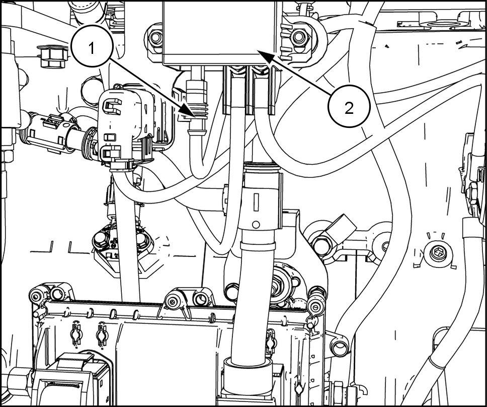
Connect the electrical connections (1) and (2) the Engine ControlUnit (ECU) (3)


Engine Engineand crankcase
NH12AF001319A NH12AF001320A 1 1
Connect the engine pre heater connector (1) the gine pre heater (2)
NHIL14AF00227AA Installcableties retainthe harnessthe 47795177 16/1 1/2014 10.1 [10.001] / 6
Fan and drive - Install (10.414)
Disconnect the fuel pumpwire connector (1) disable the fuel pump(2)
Aftercooler air supplyand returnlines - Install return air tube from cooler intake manifold (10.310)
1 Crankthe engineoverfor threeten second This will distribute lubricating oil the engine ating systems and will allowoil pressure built before starting the
Diesel Oxidation Catalyst(DOC) Install (10.500)
Engine starter - Install AlternatorInstall
Ensure all electrical components are working properly
Deaeration tank - Install (10.400)
Engine - Install engine oil drainline and drain valve
Next Operations
Aftercooler air supplyand returnlines - Install air supplytube from turbochargerlower coolerbox (10.310)
Selective Catalytic Reduction(SCR) mufflerand catalyst - Install Air intake system Install
Radiator coolanttubes - Install (10.400)
Connect the fuel pumpwire connector (1) the fuel pump(2) and bleedthe air from fuel injection system, described the Operators
Battery - Install
Engine cooling system - Filling (10.400)

Selective Catalytic Reduction(SCR) mufflerand catalyst - Install Exhaustpipes Install mixertube (10.254)
Checkthe engine oil leveland top f necessary
NHIL14AF00437AA
NHIL14AF00437AA 47795177 16/1 1/2014 10.1 [10.001] / 7
Startthe engineand checkall fittingsand clamps for leaks.
Enginehoodand panels Install (90.100)
Engine - Filling engine oil (10.001)
NOTICE:Monitor the instrumentwarninglight bar all times during initial enginestart ensure the enginehas proper oil Shut downthe engine immediately oil pressurenot
Exhaustpipes - Install exhausttube from turbo charger Diesel Oxidation Catalyst(DOC) (10.254)
Engine Engineand crankcase
Prior operation:
Prior operation:
Engine Engineand crankcase
Prior operation:
Prior operation: Air intake system - Remove (10.202)
C0038A
Engine cooling system - Drain fluid (10.400)
Exhaustpipes - Removemixertube
Prior operation: Selective Catalytic Reduction(SCR) mufflerand catalyst Remove (10.500)
Engine - Remove
CAUTION
Prior operation:
Aftercooler air supplyand returnlines - Removereturn air tube from cooler intake manifold (10.310)
Prior operation:
Prior operation:
Diesel Oxidation Catalyst(DOC) - Remove (10.500)
Air - conditioning compressor lines - Remove Prior operation: Engine starter - Remove Prior operation: Alternator Remove (55.301)
Prior operation:
Prior operation:
Battery - Remove Prior operation: Enginehoodand panels Remove
Engine - Removeengine oil drainline and drain valve (10.001)
Exhaustpipes Remove exhausttube from turbo charger Diesel Oxidation Catalyst(DOC) (10.254)
AXIAL FLOW®7140
Fan and drive - Remove (10.414)
Prior operation:
Unexpectedmachine movement! Disengage all Engage parking brake. Lower all attachments the raiseand engage all safety Shutoff engine. Remove key from key switch. Switch off batterykey , W ait for all machine movementstop. Failure complycould result minor moderateinjury .
Prior operation: Deaeration tank - Remove Prior operation: Radiator coolanttubes Remove (10.400)
Prior operation:
47795177 16/1 1/2014 10.1 [10.001] / 8

Engine Drain fluid (10.001)
Prior operation:
AXIAL FLOW®6140
Aftercooler air supplyand return lines - Remove air supplytube from turbochargerupper coolerbox (10.310)
NHIL14AF00397AA 3 47795177 16/1 1/2014 10.1 [10.001] / 9
Engine Engineand crankcase Park machine level surfaceand chock frontand rear NH12AF00141 1 Swingthe unloadtube outwardgain engine removal NHIL14AF00226AA 2
NOTE:Retain all hardware for installation the Disconnect the electrical connections (1) and (2) the Engine ControlUnit (ECU) (3)


Disconnectremaining electrical connections from wire harness engine. Remove all wire straps retaining the harnessthe

NHIL14AF00391AA 5
Disconnect the fuel supplyline (1)
Disconnect the fuel returnline (1) .
Disconnect the grid heater connector (1) the engine grid heaterrelay(2)
Engine Engineand crankcase

NHIL14AF00396AA 4
NHIL14AF00390AA 6 47795177 16/1 1/2014 10.1 [10.001] /
Remove the twelvebolts(1) retaining the main O gearboxthe
NH12AF001337A 47795177 16/1 1/2014 10.1 [10.001] / 1 1
Engine Engineand crankcase

NH12AF001336A 9
Attach suitablelifting chains (1) the engine lift brackets (2) and attacha suitablelifting Support the enginewhile removing the engine
NH12AF001335A 7 NH12AF001333A 8
Return the unloadtube(1) the transportposition and use support the main O gearbox (2) The main O gearboxmust supportedduringthe engine

Thank you very much for your reading. Please Click Here. Then Get COMPLETE IfNOTE:MANUAL.NOWAITINGthereisnoresponse to click on the link above, please download the PDF document first and then clickonit.

Engine Engineand crankcase 1 Remove the flangebolts(1) from the engine mounts (2) NHIL14AF00392AA 1 1 NHIL14AF00393AA 47795177 16/1 1/2014 10.1 [10.001] /


NH12AF001337A 47795177 16/1 1/2014 10.1 [10.001] /
Engine Engineand crankcase NHIL14AF00394AA NHIL14AF00395AA
Slowly lift the engine (1) awayfrom the main O gearbox (2) and remove the enginefrom the


Engine - Install
AXIAL FLOW®7140
Guide engineinto the O gearbox and install twelve gearbox engine mount
NH12AF001336A 2 47795177 16/1 1/2014 10.1 [10.001] /
Engine Engineand crankcase
NH12AF001337A 1
AXIAL FLOW®6140
Attach suitablelifting chains (1) the engine lift ets (2) and attacha suitablelifting device. Lift engine into positionthe