
This manual covers the service procedures of the TOYOTA FORKLIFT 7FGU/7FDU15 - 32 series and 7FGCU20- 32 series. Please use this manual for providing quick, correct servicing of the corresponding forklift mode;&. This manual deals with the above models as of October 1999. Please understand that disagreement can take place between the descriptions in the manual and actual vehicles due to change in design and specifications. Any change or modifications thereafter will be informed by Toyota Industrial Equipment Parts & Service News. For the service procedures of the mounted engine, read the repair manuals listed below as reference together with this manual. Repair(Reference)manuals related to this manual are as follows: TOYOTA INDUSTRIAL EQUlPMENT4YENGINE REPAIR MANUAL (NO. CE602-1) TOYOTA INDUSTRIAL EQUIPMENT 1 DZ-I1ENGINE REPAIR MANUAL (NO. CE618-1) TOYOTA Material Handling Company A Division of TOYOTA INWSRIES CORPORATION


SECTION INDEX I WE 1 SECTION I GENERALENGINETORQUECONVERTER & TRANSMISSIONPROPELLERSHAFTDIFFERENTIALFRONTAXLEREARAXLESTEERINGBRAKEBODY y I MASTCYLINDEROILPUMPOILCONTROL VALVE $3


GENERAL Page EXTERIOR VIEWS ........................................................ 0-2 VEHICLE MODEL .........................................................0-3 FRAME NUMBER ........................................................... 0-4 HOW TO USE THIS MANUAL ....................................0-5 EXPLANATION METHOD ................................................ 0-5 TERMINOLOGY .............................................................. 0-6 ABBREVIATIONS ............................................................0-6 OPERATIONAL TIPS ....................................................0-7 HOISTING THE VEHICLE ...........................................0-8 ATTENTIVE POINTS ON SAS .................................... 0-8 CIRCUIT TESTER ............................................ 0-9 STANDARD BOLT & NUT TIGHTENING TORQUE ............................................................ 0-11 BOLT STRENGTH TYPE IDENTIFICATION METHOD ...... 0-11 TIGHTENING TORQUE TABLE ........................................ 0-12 PRECOAT BOLTS ........................................................ 0-13 HIGH PRESSURE HOSE FITTING TIGHTENING TORQUE ............................................ 0-13 WIRE ROPE SUSPENSION ANGLE LIST ............... 0-14 SAFE LOAD FOR EACH WlRE ROPE SUSPENSION ANGLE ............................................... 0-14 COMPONENTS WEIGHT ............................................. 0-15 RECOMMENDED LUBRICANT QUANTITY & TYPES ................................................. 0-16 LUBRICATION CHART .................................................0-18 ..........................................PERIODIC MAINTENANCE 0-19 PERIODIC REPLACEMENT OF PARTS AND LUBRICANTS ...............................................................0-25

EXTERIOR VIEWS Pneumatic tire model Cushion tire model


0 3 VEHICLE MODEL Pneumatic Tire Models (Pn) Cushion Tire Models (Cu) Classificatron *: USA and CANADA Only Load Capaclty 3000 Ibs 3500 Ibs 4000 Ibs 5000 Ibs 6000 Ibs 6500 Ibs Series Pnl ton series Pn2 ton series Pn3 ton series Pn15ModelPn18Pn20ClassificationPn25Pn30Pn32 Vehicle7FGU15Model7FDU157FGU187FDU187FGU207FDU207FGU257FDU257FGU307FDU30 * 7FGU32 * 7FDU32 Load Capacity 4000 Ibs 5000 Ibs 6000 Ibs Series Cu2 ton series Cu3 ton series Cu25Cu20ModelCu30 Transmission Type TCTICT/CTICTICTK; TK; TICTK;T/CT/CT/C Cu32 1 6500 lbs *7FGCU32 TIC Vehicle7FGCU20Model7FGCU257FGCU30 I 4Y Engine Transmission Type TICTICTIC EngineGasoline 4Y 1DZ-ll4Y 1DZ-ll4Y 1DZ-ll4Y 1DZ-114Y 11DZ-ll4YDZ-ll4Y4Y4Y DieselDieselDieselGasolineGasolineGasolineGasolineDieselGasolineDieselGasolineDieselGasolineGasolineGasoline


FRAME NUMBER Frame No. Punching Position Pneumatic tire Cushion tire Series 1 ton series Engine 2 ton series 3 ton series 14YDZ-ll4Y Vehicle model7FGU15 4Y *: EEC spec. Punching format 7FGU187FDU207FDU257FGU30 2 ton series 3 ton series 7FGU18 - 60011 7FGU25 7FDU25 - 60011 7FGU32 - 60011 7FGU25 - 60011 1DZ-ll4Y4Y 7FGCU307FGCU257FGCU207FDU307FDU32 I 7FDU32 - 60011 7FGCU25 - 60011 I 7FGCU25@600117FGCU32-60011


HOW TO USE THIS MANUAL EXPLANATION METHOD 1. Operation procedure (1) The operation procedure is described in either pattern A or pattern B below. Pattern A: Explanation of each operation step with illustration. Pattern B: Explanation of operation procedure by indicating step numbers in one illustration, followed by explanation of cautions and notes summarized as point operations. Example of description in pattern B Step Nos. are partially sometimes omitted in illustrations. When a part requiring tightening torque instruction is not indicated in the illustration, the part name is described in the illustration frame. T= 46.1 - 48.1 (470 - 490) r34.0- 35.5) 8 DISASSEMBLY-INSPECTION-REASSEMBLY Tghtening torque unit T = N.m (kgf-cm) [ft-lbfl Disassembly Procedure 1 Remove the cover. [Point 11 2 Remove the bushing [Point 21 C Operation explained later 3 Remove the gear. Point Operations Explanation of key point for operation with an illustration [Point 11 LL Disassembly: Put a match mark when removing the pump cover. [Point 21 Inspection: Measure the bush inside diameter. Limit: 19.12 mm (0.7528 in)


2. How to read components figures (Example) (1) The components figure uses the illustration in the parts catalog for the vehicle model. Please refer to the catalog for checking the part name. The number at the right shoulder of each components figure indicates the Fig. number in the parts catalog. FIG number in parts catalog I 3. Matters omitted in this manual (1) This manual omits description of the following jobs, but perform them in actual operation: @ Cleaning and washing of removed parts as required @ Visual inspection (partially described) TERMINOLOGYCaution:lmportantmatters negligence of which may cause physical damage. Be sure to observe them. Note:lmportant items negligence of which may cause breakage or breakdown. And operation procedure requiring special attention. Standard: Values showing allowable range in inspection and adjustment. Limit: Maximum or minimum allowable value in inspection or adjustment. Abbreviation (code) ASSY Meaning Abbreviation (code) Meaning Assembly Cu Cushion tire modelsLH Left hand SAESASSST 5-m OOTTK;T=U/SW/ U UC M/T Society of SystemEngineersAutomotive(USA)ofactivestabilitySpecialservicetoolStandardTighteningtorqueTorqueconverter&transmissionNumberofteeth (00) UndersizeWithLess Long life coolant -Manualtransmission--NoloadmaximumspeedOPT01sPnPSQFVOptionOversizePneumatictiremodelsPowersteering4stagemast(Quadruple)


ENGINEPage Page .............ENGINE SECTIONAL VIEWS 1-2 V BELT TENSION INSPECTIONMAJOR SPECIFICATIONS................... 1-3 ADJUSTMENT .................................... 1-21 ENGINE PERFORMANCE ACCELERATOR PEDAL ; 1-22 m ..................... CURVES.............................................. 1-4 COMPONENTS .................................... 1-22 ENGINE ASSY ........................................ 1-6 1NSPECTION.ADJUSTMENT .............. 1-23 ..................REMOVAL.INSTALLATION 1-6 ACCELERATOR PEDAL SWITCH AIR BLEEDING FROM FUEL ..........SYSTEM (DIESEL VEHICLE) 1-9 ENGINE SPEED INSPECTION AND ADJUSTMENT .................................... I 9 ...........................................4Y ENGINE 1-9 ......................................ADZ-ll ENGINE 1-12 ........................................AIR CLEANER 1-13 SPECIFICATIONS................................. 1-13 ....................................COMPONENTS 1-13 AIR CLEANER INSPECTIONCLEANING.................................... 1-14 INSPECTION AND ADJUSTMENT (Cu2-3 ton series: EEC spec.) ......... 1-23 EZ PEDAL (OPT) ................................... 1-25 ....................................COMPONENTS 1-25 DISASSEMBLY.INSPECTION-REASSEMBLY.................................. 1-26 ADJUSTMENT ................................... 1-28 VEHICLE SPEED CONTROL SYSTEM (OPT) .................................. 1-29 COMPONENTS .................................... 1-29 CONNECTING DIAGRAM .................... 1 30 ......CLOGGING WARNING SYSTEM ELECTRICAL CIRCUIT DIAGRAM 1-31 INSPECTION .................................... 1-15 DIAGNOSIS .......................................... 1-32 ..................RADIATOR .............................................. 1-15 REMOVAL.lNSTALLATl0N 1-34 ....................................COMPONENTS 1-15 ACCELERATION AND THROTTLE........................SPECIFICATIONS 1-16 WIRE ADJUSTMENT 1 37 ................................. .........................COOLANT CAPACITY AND TROUBLESHOOTING 1-38 ANTIFREEZE TABLE ........................ 1 16 .............MUFFLER & EXHAUST PIPE 1-17 ....................................COMPONENTS 1-17 REMOVAL.INSTALLATION .................. 1-18 CATALYTICMAINTENANCEMUFFLER................................ 1-18 ................................................BAITERY i-19 ....................................COMPONENTS 1-19 SPECIFICATIONS ................................. 1-19 INSPECTION ........................................ 1-20


ENGINE1-2 SECTIONAL VIEWS 4Y Engine 1 DZ-ll Engine


1-3 MAJOR SPECIFICATIONS Gasoline Engines Diesel Engines 4Y (Pn3 ton series) t t t t t t c Gasoline :43 (58)/2600 GasolinelLPG :38 (52)/2600 LPG :40 (54)/2600 t t t I 2800 EngineItem Numbertypeofcylinders and a@gpr~tent-Combustion chamber type Valve mechanism Bore x stroke mm (in) Total displacement cm3(in3) Compression ratio Maximum power kW (PS)lrpm Maximum torque N.m (kgf-m)lrpm Minimum specific fuel consumption g/kW-h (g/PS-h)/rpm Service weight kg (Ib) No-load maximum rpm Tm Note:For2.3 ton series 1DZ-I1 models equipped with vehicle speed control system (OPT), the spec. figures and performance curve are same with those of 1 ton series 1DZ-II models. Pnl.2 ton series Cu2-3 ton series Gasolinelnlinekycle4cylinderslongitudinalWedge type OHV-(3.58391.0chaindrivenx86.0x3.386)2237(136.51)8.8 Gasoline :40 (54)/2400 GasolinelLPG :35 (48)/2400 LPG :37 (50)/2400 Gasoline :I62 (16.5)11800 GasolinelLPG :I47 (15.0)11600 LPG :I57 (16.0)11800 Gasoline :272 (200)/2300 GasolinelLPG :258 (190)/2400 LPG :252 (185)/2400 1342600(295) Engine Numbertypeofcylinders and arrangement Combustion chamber type Valve mechanism Bore x stroke mm (in) Total displacement cm3(in3) Compression ratio Maximum power kW (PS)lrpm Maximum torque N.m (kgf-m)lrpm Minimum specific fuel consumption glkW-h (g/PS-h)/rpm Service weight kg (Ib) No load maximum rpm rpm 1DZ 11 (Pnl ton series) Diesel 4-cycle lnline 4 cylinders longitudinal Whirl chamber type OHV167(3.38686.0geardrivenx107.0x4.213)2486(151.71)21.540(55)/2400(17.0)/1600252(185)/1400162(357)2600 1 DZ-I1 (Pn2-3ton series) t t t t C t t 44 (60)/2600 t t t 2800


Point Operations [Point 11 Removal:Putamatch marks on the fuel hose and the coupler. [Point 21 Removal:Putamatch mark on the radiator and torque converter cooler hose. [Point 31 Removal Installation: SST 09010 20111 71 - GI 09010 23320 71 -4 Removal:Tentatively hoist up until the mounting bolt completely comes out from the hole in the frame. [Point 41 Removal:Useastraight edge screwdriver for separation. If the fitting is too tight, change the SST hook position and adjust the engine angle for easier separation.


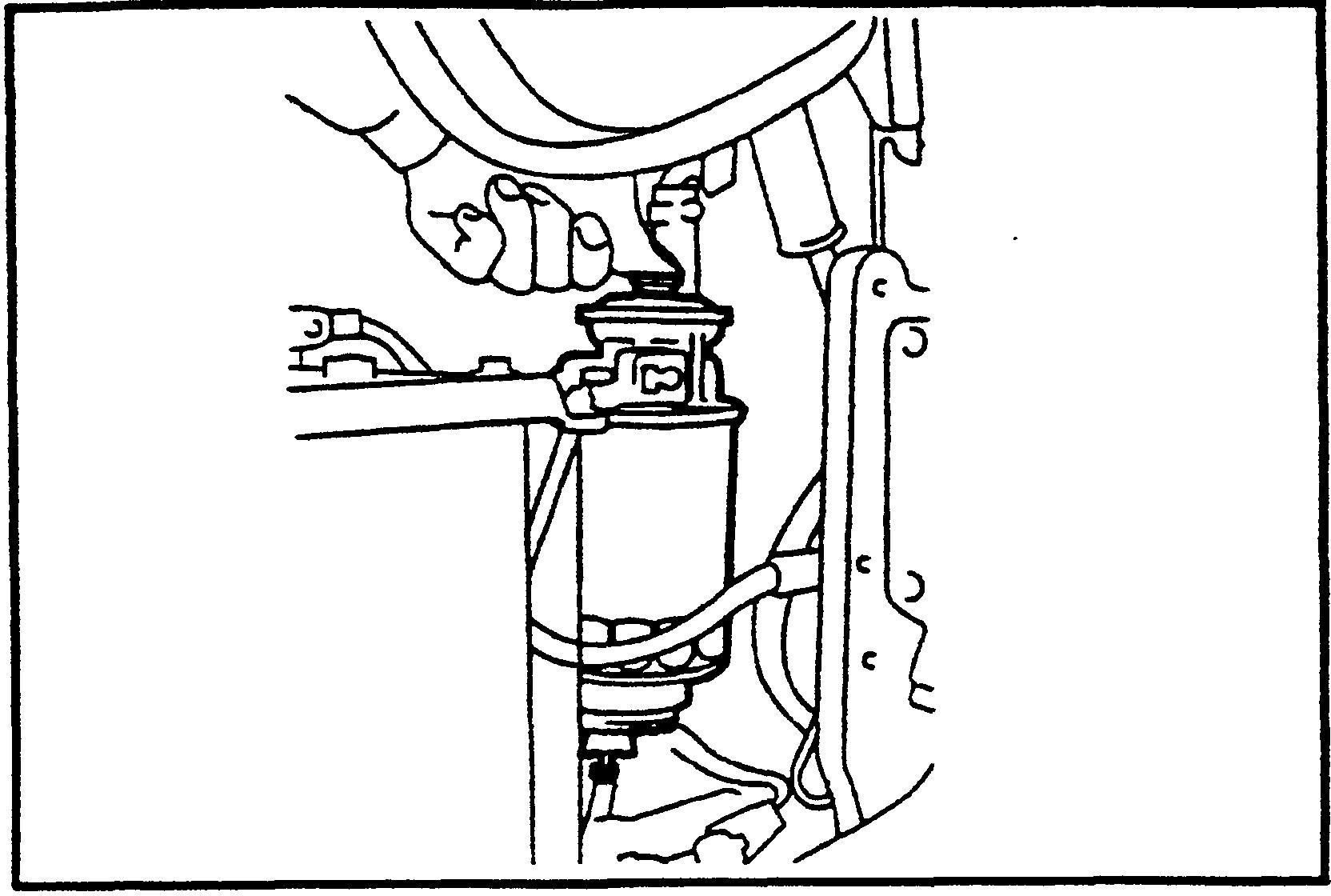
AIR BLEEDING FROM FUEL SYSTEM (DIESEL VEHICLE)
B tor 4Y IdlingENGINEspeed and idle up speed inspection and adjustment<Gasoline Vehicle> 1. Install the engine speedometer.
2. Disconnect the idle up actuator and inspect the idle up speed.Standard: 1000 a 30 rpm
Note:Warm up the engine, set the vehicle to the following conditions, and conduct inspection and adCoolantjustment.temperature: 80°C (176OF) or more, engine oil: 70°C (158'F) or more, operating oil temperature: 50°C (122OF) or more, auto choke in release state (4Y engine)
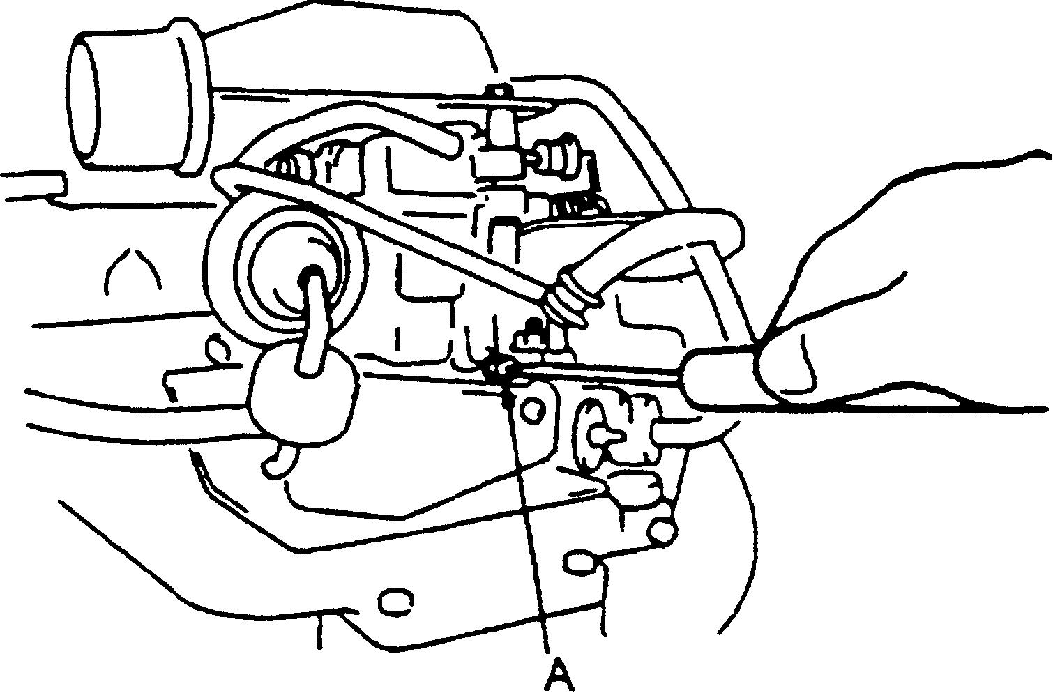
3. If the measured value is out of the specified range, adjust by turning adjusting screw B.
ENGINE
7. If the speed is still higher after adjustment in 3 above, adjust using the following procedure:
1. Operate the hand pump of the fuel filter until the pump operating force becomes heavy. SPEED INSPECTION AND ADJUSTMENT
4. Connect the idle up actuator. 5. Check the idling speed. Standard: 800 5 rpm
6. If the measured value is out of the specified range, adjust by adjusting screw A.


(2) If the idle up actuator rod and adjusting screw B are in contact with each other, turn adjusting screw 6 coun-
A Regulator
2. Disconnect the idle up actuator and inspect the idle up Standard:speed.LPGIGasoline: 1000 2 30 rpm
1.<LPG/Gasolineterclockwise.orLPG>Installtheenginespeedometer.
4. If the measured value is out of the specified range, make adjustment according to the following procedure: (1) Make adjustment by turning adjusting screw B (LPG vehicle) or C (LPGIgasoline vehicle). (If less than the standard, turn adjusting screw A counterclockwise beforehand.)
3. Check the idling speed.
(3) Determine the positions of adjusting screws B and C by repeating steps (1) and (2) until the value obtained in step (2) satisfies the standard.
(1) If the auto choke cam is contacting although the coolant temperature is as specified above, replace the auto choke.
(4) Slowly turn adjusting screw A clockwise until the CO concentration becomes 2 to 3%, and then turn it 45 degrees counterclockwise from the position where the speed begins to drop.
(2) Slowly turn adjusting screw A clockwise or counterclockwise until the maximum speed is obtained.
Standard:LPGIGasoline: 800 :,sarpm LPG: 800 :,50 rpm


(2) If the measured value is out of the standard range, make adjustment according to the following procedure:
@ Turn the bushing for adjustment, while holding the adjusting screw of the air governor immovable with a straight edge screwdriver.
Cu2-3 ton series: .......... 2600 f 50 rpm Pn3 ton series: ............. 2800 f 50 rpm
@ Return the screw by 1110 of a turn to eliminate twisting of the spring in the air governor.
@ Turn the adjusting screw counterclockwise to decrease relief down.
4YStandard:engine:Pnl-2ton series: .......... 2600 f 50 rpm
(1) Operate the tilt lever fully backward with the engine running at the maximum speed, and measure the decrease in speed (relief down) upon full relief.
(2) If the measured value does not satisfy the standard,make adjustment as follows: Remove the seal and loosen the lock bolt.
Standard: Within 300 rpm
(2) If hunting occurs a few times or more, make adjustment according to the following procedure:
@ Return the screw counterclockwise by 114 of a turn.
@ Finally,.tumit by 1110 of a turn to eliminate twisting of the spring in the air governor.
@ Fully depress the accelerator pedal.
5. Repeat adjustments in steps 2 to 4 until respective standards are satisfied. 6. Seal the lock bolt.
3. Check and adjust relief down.
4. Check and adjust hunting. (1) Check for hunting upon tilt relief at the no load maximum speed.
@ Adjust the no-load maximum speed.
(1) Measure the speed when the accelerator pedal is fully depressed.
@ Adjust the no load maximum speed.
No-load Maximum Speed Inspection-Adjustment
<Gasoline, LPG or LPGlGasoline Vehicle>
@ Repeat steps @, @ and @ until the measured value satisfies the standard.
1. Install the engine speedometer.
@ Turn the adjusting screw clockwise by 112 of a turn or more.
2. Inspect and adjust the no load static maximum speed.
@ Repeat steps @through @ until hunting occurs no more.


3. If the measured value is out of the standard, loosen the lock nut and make adjustment by turning adjusting screw A. No-load Maximum Speed Inspection.Adjustment Install the engine speedometer. Inspect and adjust the no-load maximum speed. Measure the speed when the accelerator pedal is fully depressed. DZ-ll engine: 1 ton series: 2600 f 50 rpm Vehicle speed control system spec.: 2600 f 50 rpm ton series: 2800 f 50 rpm
....................
2.3
,
3.
@
4.
Standard:1
1. Install the engine speedometer. Check the idle speed. Standard: 750 f 25 rpm
2.
Standard: Within 200 rpm Seal the adjusting screws after the end of adjustment.
@
1.
.................
(2) If the measured value does not satisfy the standard make adjustment as follows: Remove the seal and loosen the lock nut. Make adjustment by turning adjusting screw B. Check and adjust relief down. Operate the tilt lever fully backward with the engine running at the maximum speed and measure the decrease in speed (relief down) upon full relief.
(1)
..............
1DZ-ll ENGINE Idle Speed Inspection.Adjustrnent
2.
(1)


1-13 AIR SPECIFICATIONSCLEANERCOMPONENTSIntakeTypeSize Filteringtypearea cm2(in2) Others Single Cyclone(STD)type 7inch Fresh air introduction type 18600 (2883) With evacuator valve Double (OPT) t t Jt Outer: 18600 (2883) Inner. 510 (79.1) t


(1) After cleaning, place an electric bulb in the element to inspect any damage in the element. If any pinhole, tear or damage is found, replace it witti a new element.
Vehicle without AIR CLEANER CLEANING-INSPECTION
(1) For ordinary cleaning, blow with compressed air [690 kPa (7kgflcm2) [I00 psi] or less] vertically along the pleats from the inside of the element. If heavily contaminated, washing is possible.
4. Clean the evacuator valve (dust discharge valve).
6. Element replacement Replace the element after it is washed six times or generally at intervals of 12 months. 7. Install the element. (1) Install the evacuator valve in the illustrated direction.
1. Open the engine hood. 2. Remove the element. Note:In case of the double element type (OPT), do not remove the inner element for other than replacement.
3. Clean the element.
Note:Do not damage the element during washing. Never use compressed air or hot air for drying.
(2) Element washing method Dissolve neutral detergent in tepid water (approx. 40°C (104°F)) and immerse the element in it for about 30 minutes. Then, rinse the element well with clear water. [Water pressure: 275 kPa (2.8 kgflcm2) [40 psi] or less]After washing, naturally dry the element or dry the element with a dryer (cold air).
(7) Hold the tip end of the evacuator valve and discharge dust and dirt from the inside of the valve.
5. Inspect the element.


CLOGGING WARNING SYSTEM INSPECTION 1. Warning lamp inspection (1) See that the air cleaner warning lamp comes on when the ignition switch is turned ON and goes out when the,enginestarts. 2. Individual inspection (1) Use a mity vac to apply a negative pressure to the vacuum switch, and inspect conduction. GasolineStandard models: 2942 2 294 Pa (300 2 30 mm H20) (22.1 f 2.2 mmHg) [11.81 f 1.18 in H,O] [0.870 2 0.087 in Hg]: Conduction Diesel7473models: f 569 Pa (762 2 58 mm H,O) (56.0 2 4.3 mmHg) r30.00 + 2.28 in H20] [2.205 f 0.169 in Hg]: Conduction RADIATORCOMPONENTS


SPECIFICATIONSCOOLANTCAPACIN AND ANTIFREEZE TABLE Unit: e (US gal) FinTypetypeCoolantcapacity (in radiator) Cap opening pressure kPa (kgflcm2) [psi] Others SeeCormgatedCrossflowfinthetablebelow 88 i 14.7 (0.9 i 0.15) [13 f 2.11 Built in torque converter cooler Note:The total amount of coolant does not include the capacity of the reservoir tank. Reservoir tank capacity: 0.6t (0.16 US gal) (at FULL mark position) capacityRadiator amountTotal 8.58.5coolantof(2.24)(2.24)9.6(2.53)9.6(2.53)8.5(2.24)Pnl ton series Pn2.3 ton series Cu2.3 ton series LLC mixing ratio at 30% (to - 1 2.92.62.6(5OF))5OC(0.69)(0.69)(0.77)2.9(0.77)2.6(0.69)1lDZ-Il4Y4YDZ-II4Y 2.7 (0.71) 2.7 (0.71) 3.7 (0.98) 3.7 (0.98) 2.7 (0.71) LLC mixing ratio at 50% (to - 35OC (4.34.331°F))(1.14)(1.14)4.8(1.27)4.8(1.27)4.3(1.14) 0.50.40.4mixingAntirustat5%(0.11)(0.11)(0.13)0.5(0.13)0.4(0.11)


Thank you very much for your reading. Please Click Here. Then Get COMPLETE IfNOTE:MANUAL.NOWAITINGthereisnoresponse to click on the link above, please download the PDF document first and then clickonit.

MUFFLER & EXHAUST PIPE COMPONENTSGasolinemodel 1702 1702-362A Diesel model (UL-DS) 1702-361A


Note:Themuffler can be removed by either of the two methods shown below. @ Remove the muffler after removing the counterweight. @ Remove the muffler after removing the radiator Wlcounterweight. Here, method @ is explained. Removal Procedure 1 Remove the counterweight. (See p. 9 7.) 2 Disconnect the exhaust pipe. 3 Remove the muffler Witail pipe. 4 Disconnect the tail pipe from the muffler. Installation Procedure The installation procedure is the reverse of the removal procedure. CATALYTIC MUFFLER MAINTENANCE Replace the muffler ASSY every year (2000 hours) on either the gasoline or diesel engine vehicle.

BATTERYCOMPONENTSSPECIFICATIONS Battery type list (The battery is selected according to the equipped engine.) 1DZ-ll STD GR35 GR24R (JIS 55D23L) (JIS 80D26L) (JISGR24R80D26L) c 55 c 19.0 (41.9) (JISGR3555D23L) Voltage V 5 hour rate capacity Ah Specific gravity of battery fluid in use (at 20°C (68°F)) Battery weight kg (Ib) 12 48 16.21.280(35.7)


