
11Z, 122 : Diciembre de 1990 132 : Septiembre de 1996 142 : Julio de 1996 En cuanto a cambios posteriores, consulte /as Noticias de Repuestos y Servicio. Toyota se reserva el derecho a realizar cambios en /as especificaciones y en las descripciones, sin incurrir en ninguna obligacion y sin previo aviso.
manual de reparaciones contiene la informacion relativa a 10s modelos fabricados en 10s periodos siguientes:
Le aconsejamos que se familiarice completamente con este manual para aprovechar a1 maximo /as caracteristicas de rendimiento y durabilidad sobresalientes de estos vehiculos que tienen montado el motor I 12, 122, 132 o 742 para realizar el servicio adecuado, con el fin de mantenerlos en condiciones de marcha optimas.Este
Toyota reserves the right to make changes in specifications and descriptions without incurring any obligation and without previous notice.
FOREWORD
Este manual de reparaciones abarca la descripcion, construction, brjsqueda de averias, remocion, desmontaje, inspeccion y reparacion, montaje e instalacion de 10s diversos componentes de 10s motores 1 12, 122, 132 y 142 equipados en 10s montacargas Toyota.
TOYOTA Material Handling Company A Division of TOYOTA INDUSTRIES CORPORATION
You are encouraged to become thoroughly familiar with this manual so as to make the most of the outstanding performance and durability features of these vehicles mounted with the 1I 2, 122, 132, 142 engine and to perform the proper servicing to maintain them in tip top running condition. This manual contains the information on the models manufactured in the following periods: 1 12, 122: December 1990 132 : September 1996 142 : July 1996 For any changes thereafter, you are asked to consult the Parts & Service News.
TOYOTA Material Handling Company A Dlv~slonof TOYOTA INWSTRIES CORPORATlON
This repair manual describes the description, construction, trouble shooting, removal, disassembly, inspection and repair, assembly and installation of the various components of the 7 IZ, 122, 132and 142model engine equipped on the To yota Forklift Trucks.


INDICE DE SECCIONES SECTION INDEX


GENERALIDADES Pagina VISTAS EXTERIORES DEL MOTOR ........................ 0-2 ................................................ABREVIATURAS 0-8 ........SUGERENCIAS SOBRE EL FUNCIONAMIENTO 0-8 PAR DE APRETAMIENTO DE LOS PERNOS Y TUERCAS ESTANDAR 0-9 GENERAL Page .......................ENGINE EXTERIOR VIEWS 0 -2 ................................SPECIFICATIONS 0 - 6 ................................ABBREVIATIONS 0 - 8 ...........................TIPS FOR OPERATION 0 - 8 STANDARD BOLT & NUT TIGHTENING TORQUE 0 - 9

0-2 0 2 VISTAS EXTERIORES DEL MOTOR ENGINE EXTERIOR VIEWS (Motor 11Z) (11 Z engine) I 1 I Vistas exteriores del motor 11 Z KAL28 24.26 112 Engine Exterior Views KAL28-24.26


I I I 1 Vistas exterlores de motor 122 122 Engine Exterior Views


0-4 0 4 (Motor 132) (132 engine) Vistas exteriores del motor 132 132 Engtne Exterior V~ews


(Motor 142) (142 engine) I I Vistas exterlores del motor 142 142 Engine Exterior Views


0081
valve timing 2 Open Valve clearance (hot engine1 mm !in) + Oil ring Open No
Starting
speed rpm +close 14' ATDC See the repalr manual for each model
ESPEClFlCAClONES (Motor 1 1 Z, 132) I Tv~e Diesel + 1 SPECIFICATIONS(11Z,132engine) No of cylinders and arrangement I In line 6 ong~tudinalcylindersarrangement + 1 Engine model 1 lZ Fuel Injection sequence 132 Combustion chamber type 1 4 2 6 3 5 Bore x stroke '17m !in1 Total displacement cc (cub in) Compression ratioDirect injection Compression pressure kglcmi lpsiirrpm Engine horsepower PS;rpm Max~mumtorque kg-m:rpm I Engine service weight kg (ibs) 330 (7261 325 +!7171
systemValve mechanism ! Overhead valve 960 x 1020 13 78 x 4 021 4429 12671 18 5 M~nimumfuel consumption at full load g PS ti Irpmi Self-starting 980x+1020 (3 86 x 4 02) 4616-12811 33 14691 85,2200260291600 I Cvlinder liner tv~e Drv I ----165 112001 Number of piston rings875 X 550 X 760Eng~nedimensions !length x width x height) mm !in1 Compression ring Intake valve timing 875 x 523 X 743
See the repair manual for each model 1 -
" BBDC
0141 30' ABDC --+-
Exhaust load IntakeExhaust Close 52 Idle 0 20 (0 0 36 (0
maximum governed speed rpm 16' BTDC
Positive
crankcase ventilat~ontype + Closed


(Motor 122, 142) (122, 142 engine) 142Engine model Type Diesel122 Bore x stroke ---No of cylinders and arrangement Fuel injection sequence Starting Combustionsystemchamber type Cycle In-ne 6 cylinders longitudinal arrangement 1 4 2 6 3 5 Self starting4 Valve mechanism loverhead valve clear driveDirect injection Total displacement cc (cub in) + Compression pressure kglcm7 (psi1 rpm Engine horsepower PS rpm Maximum torque kg-mrrpm I Engine service weight kg ilbs) 332 1730) 327 17211 4994 I3011 Minimum fuel consumption at full load SIPS-h irprnl Engine d~mens~onsllength x width x helghtl rnm 11n1 5204 13171 33 14691 3595'22002601600 18 5Compression ratlo --158,'1200 91 1 x 566 x 847 135 8 x 22 3 x 33 31 Number of piston rings 18 6913 x 602 x 832 135 9 x 23 7 x 32 81 Compression ring Cylinder liner type Exhaust valve timing Valve clearance (hot engine) mm (in1 Dry 16' BTDC 30' BTDC Intake valve timing No load maximum governed speed rpm Positive crankcase ventilation type 2 --CloseOpenOpenCloseIntakeExhaust011ring Idle speed rpm See the repair manual for each model See the repair manual for each model 52' BTDC 14" ATDC 0 20 I0 0081 0 36 I0 Closed01411 ------


INSPECTION AND MEASUREMENT
@ Assemble non-defective parts in correct sequence while observing the specified standards (tightening torque and standard values).
AdmsionEscape!zqu~erdaOb~etivomultipleSobretamahoOpclon COLOCACION 0RDENADA DE LAS PARTES DESMONTADAS a Las partes desmontadas deberan colocarse en orden Distinga las partes que va a volver a util~zarde las que va a recambar LlMPlEZA DE LAS PARTES DESMONTADAS @ Las partes que va a volver a usar deberan Impiarse y lavarse bien INSPECCION Y MEDICION S es necesaro. inspeccone y mda con cuidado las partes que va a volver a usar MONTAJE
AJUSTES Y COMPROBACION DEL FUNCIONAMIENTO
@ Always use genuine Toyota parts for replacement.
@ Use medidores y contadores y un multimetro para realizar los ajustes a 10s valores standard de servlco especificados
@ Monte las oartes que no tengan defectos en el orden correct0 mentras observa 10s standards especificados (valores del par de apretamento y standard)
SUGERENCIAS SOBRE EL FUNCIONAMIENTO PREPARACION ANTES DEL DESMONTAJE Significado Punto muerto inferior Punto muerto superior DerechaRevolucioiles por mnuto Herrarnienta especial de servicio CarreraStandardPardeapretamentoSubtarnafio a Prepare las herramentas mecanicas, 10s instrumentos de medicion y las SST necesarias antes de comenzar a trabajar @ Cuando desmonte un conjunto complicado, punzone o ponga marcas de acoplamiento en lugares que no afecten el funcionamiento para facilitar el remontaje Cuando repare el sistema electr~co,comience a traba~ar despues de desconectar el cable del terminal negativo de la
WASHING OF DISASSEMBLED PARTS
a Thoroughly clean and wash the parts to be reused
NEAT ARRANGEMENT OF DISASSEMBLED PARTS
SubStandardassemblyTighteningtorqueTopdeadcenterUndersize
ASSEMBLY
Antes punto muerto inferior Antes punto rnuerto superior Despues punto muerto inferior Despues pJnto rnuerto superior
ExhaustIntakeLefthand 1
Meaning optionRighthandRevolutions per minute Special service tool
@ Coat sealant at necessary places on gaskets, oil on sliding contact surfaces, specified oil or grease on specified sllding contact surfaces, and MP grease on oil seal l~psbefore reassembly.
@ Revsta con empaquetadura de sellado 10s lugares necesarios de las juntas las superficies de contacto de deslizamento y de aceite con aceite o con grasa especificados las supeifcies de contacto de deslizamento especficadas y con grasa MP 10s bordes de las juntas hermet~casde aceite antes del remontaje
Abbreviation(code)OPTRHrpmSSTSTDSUBASSYT=TDCUIS
@ Whenever a part is removed, inspect the installation state, deformation, damage, roughening state and surface defects of the part.
PMSPMIAbreviaturabateria(codigo)(BDC)(TDC)RHrpmSSTstSTDT=UISAPMSAPMIAbreviatura(codgo)(BBDC)(BTDC)DPMI(ABDC)DPMS(ATDC)EXIN LH M P 0 S OPT (OPC j INSPECCION DURANTE EL DESMONTAJE a Cada vez que saque una parte. nspeccione el estado de ~nstalacion,la deformacon. el deteroro. la aspereza y defectos de ia superficie de dicha Significadoparte
@ Arrange removed parts neatly and in good order. Distinguish the parts to be reused from the parts to to be reolaced.
INSPECTION DURING DISASSEMBLY
ADJUSTMENTS AND OPERATION CHECK
@ When disassembling a complex unit, punch or draw matching marks at places not affecting functions to make reassembly easy. When repairing the electrical system, always disconnect the battery negative terminal before starting operation.
TIPS FOR PREPARATIONOPERATIONBEFOREDISASSEMBLY
Meaning AfterAssemblybottom dead center After top dead center Before bottom dead center Before top dead center Bottom dead center
@ Use sempre partes genuinas Toyota para el recambio
a Prepare necessary mechanic tools, measuring tools and SSTs before starting operation.
@ Use gauges and a multmeter and make adjustments to the specifled service standard values.
a If required, carefully inspect and measure the parts to be reused
@ Use siempre empaquetaduras juntas de empaquetadura y pasadores de chaveta nuevos para el remontale
@ Always use new pack~ngs,gaskets and cotter pins for reassembly,
ABREVIATURAS ABBREVIATIONS


are
standard tightening
indicated. Judge
STANDARD BOLT & NUT TIGHTENING TORQUE
list below and
Standard bolt and nut tightening torques not the torque as shown Find out the straight type of bolt from the then find bolt
the
PAR DE APRETAMIENTO DE LOS PERNOS Y TUERCAS ESTANDAR Nose ndca el par de apretamento de 10s pernos y tuercas estandar Juzgue el par de apretamento estandar de la manera slguiente 1 Averigue el t~pocorrect0 de perno en a lhsta slgulente y luego encuentre el par de apretamlento del perno en la tabla 2 El par de apretamlento de a tuerca se puede juzgar sabendo el tipo de perno correspond~ente METODO DE IDENTIFICACION DEL TIP0 DE RESISTENCIA DE LOS PERNOS 1 ldent~f~cac~onsegun la forma del perno 2 ldentif~cac~onsegun el numero de la parte Perno de cabeza hexagonal No. de la parte 4 16 1-40625 TLT-;;;;;;;;m)claseDiametro , PernoNo.f~jode la parte 92132 40614 [I,-:::-) Clase Diametro
below. 1.
tightening torque from the table. 2. The nut tightening torque can be judged from the mating bolt type. BOLT STRENGTH TYPE IDENTIFICATION METHOD F-0flangebolt1 linesTwo ~r:rudlng - -4 1. Ide~tificationby bolt shape 2. Identification by part No. St~dbolt 17 Welded 92132-40614 bolt 4 T Length irnrn) D~ameter i mm i Hexagon head bolt Parts No. 0'611-40625 'C~ameter i mm ) Shape and class Hexagon ,@ Bait head No. head bolt Class ;;/;d No mark 4 T Grooved 6 T BARM87 Class 4=3 ~~~~7=7T0 No mark 4T I


Y TUERCAS REVESTlDOS CON UN AGENTE DE SELLADO EN LAS PARTES ROSCADAS) 1 No use pernos revest~dosprevlamente en nnguno de 10s casos sguientes 1016146812146810121416 Class D~ameter P~tchIll 1.51.51.01.251.251.251.51,O1.251,251.251.51.5 ForNote:torque check, use the lower limit of the allowable range. If a bolt moves, retighten it according to the procedure below. m rn 140093080195400730-11026053097015002300 vI Seal lock agent mm kg cm ; it-lb ; N-m kg cm ; it-lb N~m 60 52n!b1 5.9 I45 10 I4 290 2 I 28 540 I 39 53 850 61 8 3 - -I - -1. 90 784"b 8.8 6 1.0 55 1 48m-lb 5.4 8 1.25 I30 ; 9 13 I0 25 260 19 25 2 ! 5 480 35 47 I4 1 1.5 760 55 75 lo ! 1.5 1 115Ci I 83 l I3
I4 1
2. Procedure for reuse of precoated bolts (1) Wash the bolt and bolt hole. (Wash the 84460 bolt hole also when the bolt ~sreplaced.)I95 I4 I9 730 , 810 , 59 , i4 1.5- - 1250 ; 90 123 6 l1.0 110 8 1 li 8 1.25 260 21 28 i0 1.25 , 530 38 dc 43 587T 1 2 1.5
9 13717.8193972-11255295147226
(1 ) Despues de haber sacado los pernos reves t1dos (2) Cuando se han rnovldo los pernos revest!. dos (aflojado o apretado) en la cornprobacon de apretamento, etc Nota:Paracomprobar el par, use el limite ~nfer~or del alcance permisible. Si se mueve un perno, vuelvalo a apretar de acuerdo con el procedimiento s~guiente. 7 84460 2 Procedimiento para volver a usar 10s pernos (1revest~dosprevamente)Laveelperno y el orif~c~odel perno (Lave el or~f~c~odel perno tambien cuando se recarnb~eel perno ) (2) Seque b~enel perno lavado y el orif~codel perno soplando con alre (3) Cubra con el sellador de roscas espec~ficado \as roscas de 10s pernos 6 T7 T PERNOS REVESTIDOS PREVIA- BARME8 MENTE (PERNOS
1.25 970 ; 70 95 IC'50 76 103 I4 I .5 1500 I 08 147 1700 123 I67 I6
1. Do not use precoated bolts as they are in the following cases, (1) After precoated bolts are removed. (2) When precoated bolts are moved (loosened or tightened) in tightening torque check, etc. I 6 1.01.25 T 1.25i.25 1.5 1.1) (2)Thoroughly dry the washed bolt and bolt hole by alr blowing. (3) Coat the spec~fiedseal lock agent on the bolt threads. 65 56nlbl 6.4 160 I400 7.8!
101 137 ~CI 69>n!b1
2300 166 226 -1-1BARM88
PRECOATED BOLTS (BOLTS AND NUTS COATED WITH SEAL LOCK AGENT ON THREADED PARTS)
5
I I2 I6 330 24 32 600 43 59 930 67 91
I '" L 1 .5 6 !
12502159044081012029059010501700- 1031234328.8179122858167
0 1 0 STANDARD BOLT TIGHTENING TORQUE 1 Specified toraue
0-10 PAR DE APRETAMIENTO DEL PERNO STANDARD


PUESTA A PUNT0 DEL MOTOR Pagina ........................................PARTES A PREPARAR 1 - 2 INSPECCION DELREFRIGERANTE ........................ 1 - 3 INSPECCION DEL ACEITE DE MOTOR .................... 1 - 3 INSPECCION DEL ELECTROLITO DE LA BATERIA 1 - 3 ENGINE TUNE-UP Page ITEMS TO BE PREPARED .........................1-2 COOLANT INSPECTION .......................... 1-3 ENGINE OIL INSPECTION ......................... 1-3 BATTERY ELECTROLYTE INSPECTION ............. 1-3 AIR CLEANER INSPECTION AND CLEANING ........ 1-3 INSPECCION Y LlMPlEZA DEL FILTRO DE AlRE ........ 1 - 3 CLOGGING WARNING SYSTEM INSPECTION ......... 1-4 INSPECCION DEL SISTEMA DE ......................................AVlSODE TAPONAMIENTO 1 - 4 INSPECCION Y AJUSTE DE LA CORREA EN " V " 1 - 4 INSPECCION DEL CALENTADOR DE ADMlSlON ....... 1 5 INSPECCION DE LA BOQUILLA DE INYECCION ............ 1 5 INSPECCION Y AJUSTE DE LA .............................................REGULACIONDE INYECCION 1 - 6 INSPECCION Y AJUSTE DE LA .......................................HOLGURADE LAS VALVU LAS 1 8 INSPECCION DE LA PRESION DE COMPRESION 1 - 10 INSPECCION Y AJUSTE DE LA.................................VELOCIDADDE MARCHA EN VAClO 1 - 12 "V" BELT INSPECTION AND ADJUSTMENT ......... 1-4 INTAKE HEATER INSPECTION .................... 1-5 INJECTIONINSPECTIONNOZZLE..................................1-5 INJECTION TIMING INSPECTION AND ADJUSTMENT ...............................1-6 VALVE CLEARANCE INSPECTION AND ADJUSTMENT ........................... 1-8 COMPRESSION PRESSURE INSPECTION ..........a,. 1-10 IDLE SPEED INSPECTION AND ADJUSTMENT ........ 1-12 NO LOAD MAXlFAUM GOVERNED SPEED INSPECTION AND ADJUSTMENT ................ 1-12 INSPECCION Y AJUSTE DE LA VELOCIDAD REGULADA MAXIMA SIN CARGA 1 - 12

ITEMS TO BE PREPARED Para el ajuste de a reguacion de la bornba de in Para/ecctoncornprobar a conduction de corriente de cada parte Para rnedr la tension de la correa en V Para rnedir la tenston de la correa en V Para la medicion de la boqulla de nyeccion Para el ajuste de la holgura de la valvula Para el ajuste de la holgura de la valvula Para la instalacion de la cubierta de a culata Para a rnedicon de la compresion P &/' 1 SST SST 09240 32880 7i Herramenla del aibol del embolo
Torque wrench (10 - 100 kg-crn) For head cover installation 1
Dtbujo del maquinado de la SST KALS66 sST Maching Drawing KALS66 I
Belt tension gauge Straightedge For V belt tension measurement For V bet tension measurement
Dtal Compresslor-gauge gauge For compression measurement 1 For valve clearance adjustment For valve clearance adjustment [SSTI SST 09240 32880 71 can be prepared by partial machlnlng of SST 09275 76002 71 (SST 09275-5401 0) (Toyota part No i The machining dir~ensionsare as shown below. SST Maching Drawing
SST 09240 32880 7 1 For injection pu~ptiming Tool, plunger stroke adjustment ristrLi3ientos y therrarnientas de medicton Prooaaor de c rcutos
Clrcuit tester For checking current conduction in I each Dart I Nozzle tester For injection nozzle rneasurernent I
Measuring instruments and tools
PARTES A PREPARAR [SSTI La SST 09240 32880 71 se puede preparar maquinando parcialmente la SST 09275 76002 71 (SST 092755401 0) (No de la parte de Toyotai Las dimensones de rndquinado son Ids sguientes Dbujo del maqunddo de la SST SST Linea central del Brbal del ernbolo
Medidor oe a tension d? ia correa
Regla de trazar Probador oe la boqula Caibrador de esfera Calibrador de espesor Llave de torsion (1 0 - 100 kgcm ) Cornpresornetro


INSPECCION DEL REFRIGERANTE Vea la Seccon 4
Air Cleaner Element LAO1 90-6
INSPECCION DEL ELECTROLIT0 DE LA BATERIA I I Engine 011 82320 BATTERY INSPECTIONELECTROLYTE Standard:Elniveldel electrollto debera estar entre la marca de nivel superior a y la de nivel inferior @ La gravedad especifica debera ser de 1,28 (a SiPrecaucion:20°C).elfluidodelabateria es insuficiente, aAada agua destilada.
INSPECCION Y LlMPlEZA DEL FILTRO DE AlRE 1 lnspecc~on y llrnp~eradel flltro de aire (1 ) Compruebe el elemento del f~ltrode are por sl esta deterlorado, sucio o taponado (2) Use alre cornprimldo para l~mplarel elernento del filtro de alre LaPrecaucion:presionde alre debera ser de 7 k g /cm 2 (99 psi) o menos. Battery Electrolyte Level KA L33 2
Caution:Ifthebattery fluid is insufficient, add distilled water.
ElStandard:niveldel refr~gerantedel deposit0 de reserva del radiador debera estar entre las lineas " FULL " (Ileno) y " LOW " (ba~o). La concentrac~ondel LLC debera ser del 30% (50% en zonas frias) o mas, y el refrlgerante no debera estar contamlnado con aceite, etc.
Standard:Theelectrolyte level shall be between 1 UPPER LEVEL and 2 LOWER LEVEL. The speciflc gravlty shall be 1.28 (at 20'~).
COOLANT INSPECTION See Section Standard:4Thecoolant level in the radiator reserve tank shall be between the FULL and LOW lines. The LLC concentration shall be 30% (50% in frigid zone) or more, and the coolant shall not be contaminated with oil, etc. Inspecting the Coolant KAHSlO9lnspect~ngthe Coolant KAHSlO9 ENGINE OIL INSPECTION Standard:Theoillevel shall be between F and L on the dipstick. The oil shall not be heavily contaminated, and the viscosity shall be proper. Neither coolant nor light oil shall exist in the engine oil.
AIR CLEANER INSPECTION AND CLEANING 1. Air cleaner element inspection and cleaning (1) Check the alr cleaner element for damage, dlrt and clogg~ng. (2)Use compressed air to clean the air cleaner element. TheCaution:air pressure shall be 7 kg/crn2 (99 psi) or less. Battery Electrolyte Level KAL33-2 Air Cleaner Element LA0190-6
INSPECCION DEL ACEITE DE MOTOR Standard:Elnivelde aceite debera estar entre las marcas " F " y " L " del medidor de nlvel. El aceite no debera estar muy contaminado y su VIScosldad debera ser adecuada. No deberan mezclarse el aceite de motor con aceite ligero ni refrigerante


LlMPlEZA DE LA CAJA DEL FILTRO DE AlRE Air cleaner case cleaning AIR mCLEANER AIR mCLEANER
INSPECCION DEL SlSTEMA DE AVISO DE TAPONAMIENTO
Standard " V " belt tension: inspection
1. Clean the inner and outer surface of the with cloth.
1 Inspection on vehicle Check that the air cleaner warning lamp on the Instrument panel comes on when the key sw~tchis set to ON, and that it goes off when the engine starts 1 nspeccion en el vehcuo Compruebe que la lampara de aviso del f:tro de aire de panel .n.strumental se encende cuando el nterrupto: de la ilave se coloca en 'ON' (covexion). y que se aoaga cuando se pone en marcha el motor Warning Lamp LAOS5151I Warning Lamp LAOS5151 I I 2. Indlvldual inspection Check current conduction when a negative pressure is applied to the vacuum switch.2 nspeccion Compruebeindividuallaconducc~bn de a corriente cuando se aplca una preson negativa al interruotor de vacio Standard:112,132: 655 rnm Aq or more 122, 142: 762 mrn Aq or more Estandar:112,132: 655 mm Aq o mas 122, 142: 762 mm Aq o mas I
Inspecting the Vacuum Swltch KAHS125lnspect~ngthe Vacuum Sw~tch KAHS125
" V " BELT INSPECTION AND ADJUSTMENT 1. " V " belt inspection (1 Check that the belt is correctly installed. (2) If squealing or slipping exists, check the belt surface in contact with the pulley for wear, damage and scratches, and the pulley for surface defects. 131 Apply SST (belt tension gauge) to the center of the belt between the aternator and water pump, and measure the " V " belt tension SST 0921 6-76001 71 (SST 0921 6 00020)
INSPECCION Y AJUSTE DE LA CORREA EN " V " 1 Inspeccon de a correa en " V " (1) Compruebe que la correa esta correctamente nstalada (2) S hay chirrido o resbalarniento, cornpruebe la superf~cede la correa en contacto con la polea por s nay desgaste. deteroro o rayaduras. :.la polea poi si tiene defectos en su superfce (3) Aplique la SST (medidor de tension de correas) a1 centro de la correa entre el alternador y la bornba de agua. y rnida a teqson de la correa en "V" SST 0921 6-76001-71 (SST 0921 6-00020) Inspecting the Belt Tension KAL29-4 lnspect~ngthe Belt Tenslon KAL29 4
Tension standard de la correa en " V " [TensionGauge81669 Correa en " V " nueva kg. (Ib.1 Para la lnspecclon general kg. (Ib.1 Tenston Gauge 81669 1 1Z, 132 122. 142 1 12. 132 122. 142 38 - 62 (8453-77!116-1691137)2040(44-88)3357(72-1251
1 Lmpe as superfic es interior y exterior de ,a cdja con un trapo CLOGGING WARNING SYSTEM INSPECTION


(1) Afloje el perno de ajuste A y el perno de fijacio~B (2) Tensone la correa apicando una palanca de 300 - 400 mm (1 2 - 16 " ) de larga al alternador y aprete el perno de ajuste A (3) Aprete el perno de fijacion B (4) Compruebe la tension de la correa (tension o flexion)
INSPECCION DEL CALENTADOR DE ADMlSlON 1 Desconecte los cables de calentador de admiston 2 Compruebe la continuldad de calentador de adrnsion(1)Compruebe la cont~uidadentree1 terminal @ y el term~nal3 de calentador de adms~on INSPECCION DE LA BOQUILLA DE INYECCION 1 lnspecc~onde la pres~onde ~nyeccionde la boquilla de inyeccion (1) Saque a boquilla de nyecc~on (2) lnstale la boquilla en el probador de Accioneboqullasrapidarnente la palanca del probador para que haya inyeccion varias veces con el fin de sacar el carbon que haya en 10s orif~ciosde inyeccion (3) Baje lentamente la palanca del probador para aumentar la presion y lea la presion inrnediatarnente antes de que descienda repentinamente la ~ndcacion Pres~onde inyeccion180standardkg/cm2 (2560 PSI) Presi6n de inyecci6n esthndar: 1 12. 12Z (tip0 de 2 resortesi 180 + 5 kg/cm 2 117650 + 490 kPal 112, 122 (tip0 de 1 resorte). 200",0 kglcm 2 119610 ' kPai 180132 + 5 kglcm2 (17650 i 490 kPa) 142230 + 5 kglcrn 2 (22560 + 490 kPai Para la (empujando~nspecciongeneralcon10kg) mm,(pul,) Pressure 10 kq 8 13 (0.31 -0.51 ) Inspecting the "V" Belt Flexure 81668 Adjusting the Fan Belt Tension KAL29-8 Inspecting the Intake Heater KAL3-14
(4) When a tension gauge is not available, push the center of the belt between the alternator and water pump with a force of 10 kg (22 Ib) and measure the flexure.Standard " V " belt flexure: 2. " V " belt adjustment (1) Loosen adjust~ngbolt A and fixing bolt For general inspection (pushed with 10 kg) rnm (in) pressure 10 kg 8 13 (0.31 - 0.51) Inspecting the "V" Belt Flexure 81668 B. (2) Tension the belt by applying a 300400 mm (12 - 16 in) long lever to the alternator, and tighten adjusting bolt A. (3) Tighten fixing bolt B. (4) Check the belt tension (tens~on or flexure).
(4) Cuando no haya dsponbe un meddorde tensones. empuje el centro de a correa entre el alternador y la bornba de agua con una fuerza de 10 kg (22 lb) y mida a flex~onFlex~onstandard de la correa en "V": 2 Aluste de la correa en " V "
Standardsuddenly.injection pressure: 1 12, 122 12 spring type): 180 f 5 kgicrn 2 12560 5 70 psi) 117650 ? 490 kPal 1 12, 122 (1 sprlng type): 200 +Ao kgicrn 2 12840 [I9610+ppsi) +t80 kPal 180132: * 5 kgicm 2 12560 ? 70 psi) [I 7650 ? 490 kPal 142:230 f 5 kg/crn2 (3270 f 70 psi) Injection Pressure F2516 [22560 ? 490 kPal
L I Injection Pressure F2516
INJECTION NOZZLE INSPECTION 1 lnlection nozzle inlectlon pressure (1)~nspectionRemovethe injection nozzle. (2) Install the nozzle to the nozzle tester. Operate the tester level quickly to cause injection a few times to remove the carbon at the injection holes. (3) Slowly lower the tester lever to increase the pressure and read the pressure im mediately before the indication drops Inspecttngthe Intake Heater KAL3-14
INTAKE HEATER INSPECTION 1. Disconnect the cables from the intake heater. 2. Check continuitv of the intake heater. (1) Check continuity between + terminal Adjusting the Fan Belt Tension KAL29-8 and - termlnal of the intake heater


INJECTION TIMING INSPECTION AND ADJUSTMENT INJECTION TIMING INSPECTION 1. Place the No 1 cylinder at the TDC.
i Coloque el chndro No 1 en el PMS
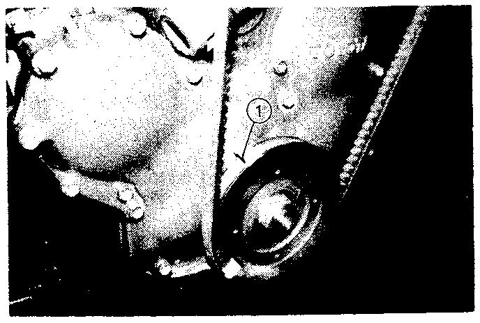
(3) Remove the bolt ar the rear end of the Injection purnp Removing the Bolt KAL29-12
1 6 INSPECCION Y AJUSTE DE LA REGULACION DE INYECCION INSPECCION DE LA REGULACION DE INYECCION
(a) Coloque la SST y un rneddor de esfera en el oriftco del perno SST 09240-32880 71
(2)Remove the fuel plpe No. 1 on njecton pump s~de.
(1) Align the crank pulley TDC notch mark with the @ timing pointer Sett~ngthe TDC KAL29-2
(1 ) Alinee a marca de la rnuesca del PMS de la polea del cgueiial con a aguja de dstribuc~ono regulation O Sett~ngthe TDC KA L29-2
Caution:Applythe tip end of the dial gauge to a flat surface. Prevent foreign matter or dust entrance during operation. Removlng the fuel pipe No. 1 KAL29-13 Removing the Bolt KAL29.12
14) Set the SST and dial gauge to the bolt holeSST 09240 32880 71
ApliquePrecaucibn:elextremo de la punta del medidor de esfera a una superficie plana. Evite que entren materias extrahas o polvo durante esta operacion. Remov~ngthe fuel plpe No 1 KAL29.13 -. k
13) Saque ei perno que i?a\( en el extremo trasero de la bomba oe n~eccon
Inspecting the Injection Timing KAL29-15 lnspectfng the Injectton Timing KAL29-15
(2) Saque a tubera de rombustIble ko en el Iddo ae a boraa de nveccon


(6)Slowly rotate the crankshaft in the forward direction until cylinder No. 1 comes to the TDC. Read the dial gauge indication there If the reading is within the standard, the setting is normal. If not, adjustment
1 Check~ngMatch Marks KAL31 - 14
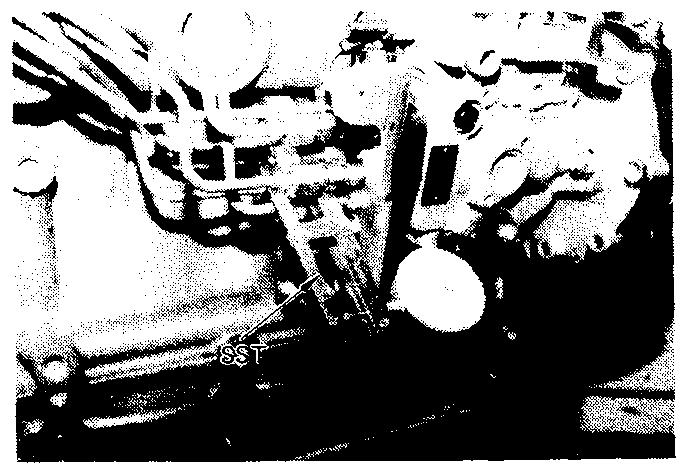
(3) Loosen injection pump set nut and the bracket underneath. Loosening the Set Nut KAL29-19 Loosen~ngthe Set Nut KAL29-19
(3) Afloje la tuerca de sujecion de la bornba de nyeccion y del soporte inferior (51 While observing the dial gauge, rotate the crankshaft in the reverse direction by a crank angle over 25' from the TDC of cylinder No. 1. When the dial gauge pointer deflection stops, set the dial gauge to 0.
Rotatsng the Crankshaft in Reverse Direction KAL29-3
(2) Loosen the joints of piping with the injection pump 1 Fuel inlet pipe 2 In~ectonpipe 3 Overflow pipe Loosening the P~p~ng KAL30-6
IS Standard:necessary.112,122: 1.56 - 1.62 rnm (0.0614 - 0.0638 in) 132: 1.36 - 1.42 rnm (0.0535 - 0.0559 in) 142: 1.66 - 1.72 rnm (0.0654 - 0.0677 in)
2. I njecton t~mingadjustment (1 Check alignment of the degree of offset between mark (B) on the timing gear case and mark (A) on the injection pump body. (To use it as theguideline in making ad]ustn>ent)
(5) Mientras obsetva el calibrador de esfera. gire el arbol del ciguehal en dreccion nversa medante un angulo del ciguehal superior a 25' a partir del PMS del cilindro No 1 Cuando se detene la desviacon de a aguja del caibrador de esfera. ajuste el medidor a cero (6) Gire lentamente el arbol de cgueiial en dreccon de avance hasta que el cilindro No 1 acance el PMS Lea la indication del caibrador de esfera S la lectura esta dentro de a standard, el ajuste es normal S no, es iecesaro ajustarStandard:112,122: (0,0611,56-1,62rnrn.4-0,0638 " ) 132: 1.36 - 1,42 rnrn. (0,0535 - 0,0559 " ) 142: 1,66 - 1,72 mm. (0,0654 - 0,0677 " ) 2 Ajuste de a "egulacior de n:tcc on (7 ) Cor?pvuebea al-e,~c15nde qrdd~de desplazamiento entre la marca (B) del caiter del ecgrariaje de ds!r bilcol y la maVca (A) de cuerpo ds a oomba de nyeccton (Para usaro como guia al realzar el ajuste ) Rotating the Crankshaft in Reverse Direction KAL29-3 I 1 Checking Match Marks KAL31 - 14 (2) Afoje las unones de as tuberas rigidas con la bornba de inyeccion a Tuberia rigda de adrnision de combustible @ Tuberia rigda de nyeccion @ Tuberia rig~dade rebose Loosening the Piping KAL30 6


Thank you very much for your reading. Please Click Here. Then Get COMPLETE IfNOTE:MANUAL.NOWAITINGthereisnoresponse to click on the link above, please download the PDF document first and then clickonit.

(6) Tighten the loosened pipe joints. (71 After the injectlon timing inspection and adjustment, remove the SST and dial gauge and install the bolt at the rear end of the pump. T = 100 - 160 kg cm (7.23 - 11.6 ft-lb) L9.8 - 15.7 N.ml
Caution: 0 Use a new copper washer. o Carefully prevent dust and foreign matter entrance. CLEARANCE
oPrecauciones:Useunaarandela de cobre nueva. 3 Evite cuidadosamente que entre el polvo o materlas extrailas INSPECCION Y AJUSTE DE LA HOLGURA DE LAS VALVULAS 1 Calente el Temperaturamotorstandard del refrigerante.75- 85°C 2 Remocion de la tuoeria rig~dade admision (1 ) Tuberia flexible de ventilation (2) 1-uberia rigda de admson @ Perno de sujecion (lado del colgador de motor) @ Perno desujecion v tueria de sujecion (lado de calentador de admison) @ Tuberia rigda de admison
VALVE
(4) Mdeva ei cuerpo de a nomba para el ajuste 6) S el valor medido en la etapa 6 de la nspeccion de la disrr~bucionde inyeccion esta por debajo del limite nferior, mdeva ia bomba en la direccion A @ S el valor medido en la etapa de a nspeccion de la distribution de nyeccion excede el limite superior, mueva la bomba en la direcc~onB (5) Apriete la tuerca de sujecion de a bomba de lnyeccion y el soporte inferior. e nspeccore de nuevo a reg~lac~onde nyeccon (6) Aprete las unones de las tuberias rigdas que se nabian aflojado (7) Despues de la nspecclon del ajuste de a regulation de nyeccon quite la SST y el calbrador de esfera e 'lnstale el perno en el extremo trasero de la bomba T = 1,O - 1.6 kgm. (7,23 - 11,6 Ib pie) 19,8 - 15,7 N,ml (41 Move the pump body for adjustment 3 If the measured value in step 6 of in - a* jection timing inspection is below the lower limit, move the pump In direction A a If the measured value in step 6 of injection timing inspection exceeds the upper limit move the pump in d~rectionB. (5) Tighten the injection pump set nut and the bracket underneath, and inspect the injection timing again. Adjusting the Injection T~ming KAL30-8 Adjust~ngthe Injection T~m~ng KAL30-8
INSPECTION AND ADJUSTMENT 1. Warm up the engine. Standard coolant temperature: 75 - 85'~ 2. lntake plpe removal (1) Ventilation hose Removing the Ventilation Hole KAL1-33 Removing the Ventilation Hole KAL1-33 (2) lntake pipe I Set bolt (engine hanger s13e) 2 Set bolt and set nut (intake heater side) 3 lntake pipe Removing the Intake P~pe KAL28-13 Remov~ngthe Intake P~pe KAL28 13


7. Measure the valve clearance of the rernalning valves. Inspecting the Valve Clearance (21 KAL28-5 Inspecting the Valve Clearance (2) KAL28 5 Adjusting the Valve Clearance KAL28-4
4. Rotate the crankshaft in the forward directlon to set cylinder No. 1 at the TDC 5. Measure the valve clearance for each of the valves shown in the figure. Standard valve clearance IN: 0.20 mm (0.008 in) (hot eng~ne) EX: 0.36 mm (0.014 in) (hot engine) Inspecting the Valve Clearance (1) KAL28 5Inspecting the Valve Clearance (1) KAL28-5
9 Apr~etea tuerca de segur~dade lnspeccione de nuevo la holgura de la valvula 3. Cylinder head cover removal (11 Bolts w~thwashers (2)Seal washers (3) Cylnder head cover Remov~ngthe Cylinder Head Cover KAL27 30
3 G~reel arb0 de c~gueial en d~recc~onde avance para colocare cnd-o No 1 en el PMS 5 M!da la holgi:ra de la valvula de cada ona de 13s valvulas most adas en la fg~~ra Holgura standard de la valvula. IN. 0.20 mm. (0,008 " ) (motor caliente) EX. 0.36 mm. (0.01 4 " ) (motor cal~ente)
6 G~reel arool d~lrg:etia en la d,recr;o- cie avance para coocare c, ndro No 6 en el PlVlS 7 M~daa holg~irade las vavuas restantes
Inspeccion de la holgura de la valvula
8 Afloje la tuerca de segurdad y gre el tor~i~liode ajuste para alustar Use un calbrador de espesor de motor para el ajuste de la holgura Holgura standard de la valvula: IN: 0,20 mm. (0.008 " ) (motor caliente) EX: 0,36 mm. (0,014 " ) (motor caliente)
3 Remocion de a cuberta de la culata de c!ndros(1) Pernos con arandeas (2) Arandelas de sellado (3) Cuberta de a culata de c lndros
Valve clearance adjustment
Remov~ngthe Cylinder Head Cover KA L27-30
9. Tighten the lock nut, and inspect the valve clearance again. Adjusting the Valve Clearance KAL28-4
Valve clearance inspection
6. Rotate the crankshaft In the forward d~rectlon to set cylinder No 6 at the TDC.
Ajuste de la holgura de la valvula
8. Loosen the lock nut and turn the adjustng screw for adjustment. Use an engine feeler gauge for clearance measurement. Standard valve clearance IN: 0.20 mm (0.008 in) (hot engine) EX: 0.36 mm (0.014 in) (hot engine)


INSPECCION DE LA PRESION DE COMPRESION 1 Caiente el Temperaturamotorstandard del refrigerante: 75 - 85°C 2 Hemocion de la tuberia rig~dade admision (1 ) Tuberia flexible de ventilacion Removing the Ventilation Hose KAL1-34 (2) Tuberia rigda de admison @ Perno de sujecon y tuerca de sujecion @ Tuberia rigda de adrnlson
10 lnstalacion de a cub~ertade la culata de cllindros(1) Cuberta de la culata de cilindros (2) Arandelas de sellado (3) Pernos con arandelas T = 50 - 90 kgm. 13.6 - 6.5 b-pie) 14.9 - 8.8 N mi
11. lntake pipe installat~on (1) lntake pipe (2) Set bolt and set nut (3) Ventilation hose Installing the lntake Pipe KAL28 13
10. Cylinder head cover installation (1 ) Cylinder head cover (2)Seal washers (3) Bolts with washers T= 50 - 90 kg cm (3.6 - 6.5 it-b) [49 - 8 8 N.ml Installing the Cylinder Head Cover KAL27 22 Installing the Intake Pipe KAL28-13
Removing the Intake Pipe KAL28-13 Rernovsng the lntake Plpe KAL28 13
COMPRESSION PRESSURE INSPECTION 1. Warm up the engine. Standard coolant temperature: 75 - 85'C 2. intake plpe removal (1 ) Ventilation hose (2) lntake pipe I Set bolt and set nut 2 lntake pipe Removing the Vent~lat~onHose KAL1-34
11 lnstalacion de la tuberia rigida de admson (1 ) Tuberia rigda de admison (2) Perno de sulecion y tuerca de sujecion (3) Tuberia flexible de ventilacion Installing the Cylinder Head Cover KAL27 22


3 Rernocon de la tuberia rigida de nyecc6n y de a tuberia rigida de filtraciones de as boquillas
Removing the Nozzle Leakage PlPe KAL27 5 pression measurement. Removing the Nozzle and Nozzle Holder KAL26-32 [I961 KPall260 rpm
5. Medtcion de la compresion
4 Rernocon de todos 10s sujetadores de las boquillas y de las boquillas (1 ) Tuercas de sujecon (2) Sujetadores de las boquillas y boquillas
VeaPrecaucion:lapagina 3 19 en cuanto al metodo de instalacion de la boquilla y sujetador de
Nota:Useuna bateria totalmente cargada para mantener la veloc~daddel motor superior a las rprn especificadas. (3) Repita las etapas anteriores (1) y (2) para todos 10s cilindros Limite de diferencia entre 10s cilindros: 2 kg/cmZ(28 psi)/260 rprn [I96 KPa11260 rprn (4) Si la presion de compres~onde cualquier cilindro es inferior al limite o si la diferencia de preson entre 10s cilindros es superior al limite, afiada un poco de aceite de motor por el or!ficio de la boquilla y rep~talas etapas anteriores (1 ) a (3) a SI al echar aceite aurnenta la presion. 10s segrnentos del piston y el calibre de cilindro pueden estar desgastados @ S a preson es todavia baja despues de haber aliadido acelte. la causa puede ser agarrotamiento de la valvula, defect0 de contact0 de la valvula o escape de pres~onpor la junta de empaquetadura
PongaPrecaucibn:enmarcha el motor para que salgan las materias extraiias de 10s cilindros antes de comenzar la medicion de la compresion.
Measuring the Compression Pressure KAL26-28 from the nozzle hole and repeat steps (1 ) to (3)above. 3 If the 011add~tionraises the pressure, the piston rings and cyl~nder bore may have been worn. If the pressure is still low after the oil addition, valve seizure, valve contact defect or pressure leakage from the gasket may be the cause.
Caution:Seepage 3 - 19 for the nozzle holder and nozzle installation method. Removing the Nozzle Leakage Pipe KAL27-5 Removing the Nozzle and Nozzle Holder KAL26-32 Measuring the Compression Pressure KAL26-28
(2) Ponga en rnarcha el motor y rnida la presion de Standard:compresion33kg/crn2 (469 psi)/260 rprn [3236 KPa11260 rprn Limite: 20 kg/crn2(284 psi)/260 rprn [I961 KPall260 rprn
(1 ) lnstale el accesorio del cornpresometro al orificio de la boqu!la. e instale el cornpreJuegosometrode compresometros SST 09992 76002 71 (SST 09992-000251


