
621F TIER 4 Print No. 47387703 Service Manual Wheel Loader
621F Wheel Loader Repair Manual
47387703
Table of Contents
DescriptionSection No.
General Tab 1 Section Index - General General Torque Specifications 1001
Fluids and Lubricants 1002 Metric Conversion Chart 1003
Engines Tab 2
Section Index - Engines
Engine and Radiator Removal and Installation 2000
Stall Tests 2002 After Cooler 2003
SCR System Sensors 2020
SCR Catalyst 2030
Engine Intake Temperature/Humidity Sensor2040
DEF/ADBLUE Heater Control Valve 2050
DEF/ADBLUE DNOx Supply Module 2060
DEF/ADBLUE Dosing Injector 2070
DEF/ADBLUE Supply Tank 2080
DEF/ADBLUE Supply Tank Level and Temperature Sensor/Pick-up and Heater 2090
DEF/ADBLUE Supply Filters 2100
For Engine Repair, See the Engine Service Manual (sold separately) 84392428
Fuel System Tab 3
Section Index - Fuel System
For Fuel System Repair, See the Engine Service Manual (sold separately)84392428
Electrical Tab 4
Section Index - Electrical
Removal and Installation of Starter and Alternator 4001
Electrical Specifications and Troubleshooting4002 Batteries 4003 Instrument Cluster 4005
621F Wheel Loader Repair Manual
Table of Contents
DescriptionSection No.
Steering Tab 5
Section Index - Steering
Removal and Installation of Steering Components 5001 Steering Specifications, Pressure Checks, and Troubleshooting5002 Steering Cylinders 5005
Center Pivot 5006
Auxiliary Steering Motor and Pump 5008 Joystick Steering System (JSS) 5009
Power Train Tab 6
Section Index - Power Train
Removal and Installation of Power Train Components 6001
Transmission Specifications, Pressure Checks, and Troubleshooting6002 4 Speed Transmission 6003
Front Axle 6004
Rear Axle 6004
Drive Shafts, Center Bearing, and Universal Joints6005 Wheels and Tires 6006
Brakes Tab 7
Section Index - Brakes
Removal and Installation of Brake Components7001 Hydraulic Brake Troubleshooting 7002 Brake Pump 7003 Brake Accumulators 7004 Parking Brake 7008
Hydraulics Tab 8
Section Index - Hydraulics
How to Read Hydraulic Schematics 8000
Removal and Installation of Hydraulic Components8001 Hydraulic Specifications, Troubleshooting, and Pressure Checks 8002 Cleaning the Hydraulic System 8003
Loader Control Valve 8005
47387703
Cylinders 8006
Coupler Solenoid Locking Valve 8007
Ride Control Accumulator 8013
Ride Control Valve 8014
Mounted Equipment Tab 9
Section Index - Mounted Equipment
Air Conditioning Troubleshooting and System Chec ks For System Checks For System with HFC-134a
Refrigerant 9002
Air Conditioner System Service 9003
Removal And Installation Of Air Conditioning And Heater Components 9004 Loader 9006
Roll Over Protective Structure (R OPS), Cab Structural Frame (CSF) 9007
Cab Glass Installation 9010
Rear View Camera Installation and Removal 9020 Electrical Schematic Foldouts and Hydraulic Schematic Foldout In Rear Pocket 621F Wheel Loader Repair Manual 47387703 Table of Contents DescriptionSection No.
SECTION INDEX
GENERAL
Standard Torque Specifications . . . . . . . . . . . . . . . . . . . . . . . . . . . . . . . . . . . . . . . . . . . . . . . . . . . . . . . . . . . . .1001
Fluids and Lubricants . . . . . . . . . . . . . . . . . . . . . . . . . . . . . . . . . . . . . . . . . . . . . . . . . . . . . . . . . . . . . . . . . . . . .1002
Metric Conversion Chart . . . . . . . . . . . . . . . . . . . . . . . . . . . . . . . . . . . . . . . . . . . . . . . . . . . . . . . . . . . . . . . . . . .1003
Section
Section Number
Title
Section 1001
GENERAL TORQUE SPECIFICATIONS
1001
TORQUE SPECIFICATIONS - DECIMAL HARDWARE
Use the torques in this chart when special torques are not given. These torques apply to fasteners with both UNC and UNF threads as received from suppliers dry, or when lubricated with engine oil. Not applicable if special graphities, Molydisulfide greases, or other extreme pressure lubricants are used.
Grade 5 Bolts, Nuts, and Studs
Size
PoundInches Newton metres
1/4 inch 108 to 132 12 to 15
5/16 inch204 to 25223 to 28
3/8 inch 420 to 504 48 to 57
Size
PoundFeet Newton metres
7/16 inch 54 to 64 73 to 87
1/2 inch80 to 96109 to 130 9/16 inch 110 to 132 149 to 179
5/8 inch150 to 180203 to 244
3/4 inch 270 to 324 366 to 439
7/8 inch400 to 480542 to 651
1.0 inch 580 to 696 787 to 944
1-1/8 inch800 to 8801085 to 1193
1-1/4 inch 1120 to 1240 1519 to 1681
1-3/8 inch1460 to 16801980 to 2278
1-1/2 inch 1940 to 2200 2631 to 2983
Size
Grade 8 Bolts, Nuts, and Studs
PoundInches Newton metres
1/4 inch 144 to 180 16 to 20
5/16 inch288 to 34833 to 39 3/8 inch 540 to 648 61 to 73
Size
PoundFeet Newton metres
7/16 inch 70 to 84 95 to 114
1/2 inch110 to 132149 to 179
9/16 inch 160 to 192 217 to 260
5/8 inch220 to 264298 to 358 3/4 inch 380 to 456 515 to 618
7/8 inch600 to 720814 to 976
1.0 inch 900 to 1080 1220 to 1465
1-1/8 inch1280 to 14401736 to 1953
1-1/4 inch 1820 to 2000 2468 to 2712
1-3/8 inch2380 to 27203227 to 3688 1-1/2 inch 3160 to 3560 4285 to 4827
NOTE: Use thick nuts with Grade 8 bolts.
1001-3
TORQUE SPECIFICATIONS - METRIC HARDWARE
Use the following torques when specifications are not given.
These values apply to fasteners with coarse threads as received from supplier, plated or unplated, or when lubricated with engine oil. These values do not apply if graphite or Molydisulfide grease or oil is used.
Grade 8.8 Bolts, Nuts, and Studs
8.8
Size
PoundInches Newton metres
M4 24 to 36 3 to 4
M560 to 727 to 8 M6 96 to 108 11 to 12
M8228 to 27626 to 31 M10 456 to 540 52 to 61
Size
PoundFeet Newton metres
M12 66 to 79 90 to 107 M14106 to 127144 to 172 M16 160 to 200 217 to 271 M20320 to 380434 to 515 M24 500 to 600 675 to 815 M30920 to 11001250 to 1500 M36 1600 to 1950 2175 to 2600
Size
Grade 10.9 Bolts, Nuts, and Studs
PoundInches Newton metres
M4 36 to 48 4 to 5
M584 to 969 to 11 M6 132 to 156 15 to 18 M8324 to 38437 to 43
Size
PoundFeet Newton metres
M10 54 to 64 73 to 87 M1293 to 112125 to 150 M14 149 to 179 200 to 245 M16230 to 280310 to 380 M20 450 to 540 610 to 730 M24780 to 9401050 to 1275 M30 1470 to 1770 2000 to 2400 M362580 to 30903500 to 4200
Grade 12.9 Bolts, Nuts, and Studs
10.9 12.9
Usually the torque values specified for grade 10.9 fasteners can be used satisfactorily on grade 12.9 fasteners.
1001-4
1001-5
TORQUE SPECIFICATIONS - STEEL HYDRAULIC FITTINGS
37 Degree Flare Fitting
Tube OD Hose ID Thread Size PoundInches Newton metres
1/4 inch 6.4 mm 7/16-20 72 to 144 8 to 16 5/16 inch 7.9 mm 1/2-2096 to 19211 to 22 3/8 inch 9.5 mm 9/16-18 120 to 300 14 to 34 1/2 inch 12.7 mm 3/4-16180 to 50420 to 57 5/8 inch 15.9 mm 7/8-14 300 to 696 34 to 79
Tube OD Hose ID Thread Size PoundFeet Newton metres 3/4 inch 19.0 mm 1-1/16-12 40 to 80 54 to 108 7/8 inch 22.2 mm 1-3/16-1260 to 10081 to 135 1.0 inch 25.4 mm 1-5/16-12 75 to 117 102 to 158 1-1/4 inch 31.8 mm 1-5/8-12125 to 165169 to 223 1-1/2 inch 38.1 mm 1-7/8-12 210 to 250 285 to 338
Split Flange Mounting Bolts
Size PoundInches Newton metres 5/16-18 180 to 240 20 to 27 3/8-16240 to 30027 to 34 7/16-14 420 to 540 47 to 61
Size PoundFeet Newton metres 1/2-13 55 to 65 74 to 88 5/8-11140 to 150190 to 203
Straight Threads with O-ring
Tube OD Hose ID Thread Size PoundInches Newton metres 1/4 inch 6.4 mm 7/16-20 144 to 228 16 to 26
5/16 inch 7.9 mm 1/2-20192 to 30022 to 34 3/8 inch 9.5 mm 9/16-18 300 to 480 34 to 54 1/2 inch 12.7 mm 3/4-16540 to 80457 to 91
Tube OD Hose ID Thread Size PoundFeet Newton metres 5/8 inch 15.9 mm 7/8-14 58 to 92 79 to 124 3/4 inch 19.0 mm 1-1/16-1280 to 128108 to 174 7/8 inch 22.2 mm 1-3/16-12 100 to 160 136 to 216 1.0 inch 25.4 mm 1-5/16-12117 to 187159 to 253 1-1/4 inch 31.8 mm 1-5/8-12 165 to 264 224 to 357 1-1/2 inch 38.1 mm 1-7/8-12250 to 400339 to 542
Section 2000
2000 ENGINE AND RADIATOR REMOVAL AND INSTALLATION
Removal
STEP 1
ENGINE
STEP 5
BD03A040
Park machine on a level surface and lower bucket to ground. Put articulation lock in LOCKED position.

STEP 2
Stop engine. Actuate brake pedal several times to discharge brake accumulators. Put key switch in ON position and move loader control lever back and forth at least 30 times to release any pressure from hydraulic circuit. Put key switch in OFF position.
STEP 3
Slowly loosen the filler cap for hydraulic reservoir to release air pressure in hydraulic reservoir.
STEP 4
BD06F108
The master and hood raise switch are located by the battery box. Raise the hood with the hood lift motor. Put master disconnect switch in OFF position. Remove both battery covers and disconnect batteries from the machine.


BD02N160
Put a 28.4 liter (30 U.S. quart) container below radiator drain. Remove radiator cap. Remove cap and drain coolant into container. Install cap after coolant has drained. Install radiator cap.
STEP 6
BD02N160
Put a 15.1 liter (16 U.S. quart) container below engine oil drain. Remove cap and drain oil into container. Install cap after oil has drained.
NOTE: After draining oil disconnect drain hose from frame for removal with engine.
2000-3
BD03A231
Double up a nylon lifting strap (1) and slide through the exhaust stack (2) on the hood.

STEP 8
BD03A230
Place a solid steel bar through the strap, raise the hood and release tension on the lifting motor.


STEP 9
Tag and disconnect hood wiring harness connector from rear chassis wiring harness connector.
STEP 11 BD03A227
BD03A226
Remove mount bolt (1) and backup alarm wiring harness clamp from cooler housing. Have another person balance the hood and remove the hood hinge mounting bolts (2) from the cooler frame.


BD03A228
Remove the pin from the top of the lifting motor.
2000-4
STEP 7
STEP 10 BD06F109
1 2
1 2 2


2000-5
raise and remove hood
loader. Lower
platform and disconnect lifting
Tag and disconnect engine wiring harness connector from air filter restriction switch.
BD03A225
clamp on air cleaner intake hose and remove the crankcase ventilation hose.
clamps on turbocharger and air cleaner, remove the intake hose.
STEP 12 BD03A232 Carefully
from
hood onto suitable
equipment. STEP 13 BD03A224
STEP 14
Loosen
STEP 15 BD06F110 Loosen
clamp
the turbocharger for the
cooler inlet hose.
STEP 16 BD06F110 Loosen the
on
after
the clamp
and remove the
cooler
hose
the
STEP 17 BD03A115 Loosen
on the after cooler
after
inlet
from
machine.


2000-6
STEP 18 BD06F111
Loosen the clamp on the intake manifold for the after cooler output hose.
STEP 19 BD03A118
Loosen the clamp on the after cooler and remove the after cooler outlet hose from the machine.
STEP 20 BD06F110
Loosen the exhaust clamp from the turbocharger. STEP 21 BD06F112 Remove the air cleaner and muffler from the bracket.
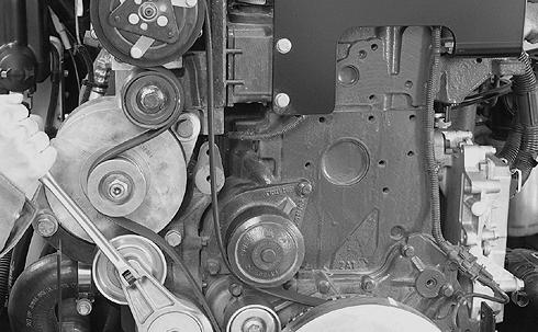
STEP 22 BD06F113 BD06F114 Remove the four mounting bolts from the belt cover, remove the cover. NOTE: After removing the belt cover remove the cover mounting brackets from the machine frame.
If


2000-7
STEP 23 BD06F115 Remove the drive belt from the engine.
STEP 24 BD06F116
Loosen clamps and remove lower cooler hose from the engine.
STEP 25 BD06F117
loader is equipped with air conditioning, identify, tag, and disconnect the engine wiring harness connectors from air compressor clutch connector (1). Remove the three mounting bolts (2) for the compressor and set the compressor on the left battery cover. STEP 26 BD06F118 Tag and disconnect the wiring from the alternator. STEP 27 BD06F119 Remove bolt securing wiring harness clamp to engine. STEP 28 BD06F120
1 2 1 2
Remove bolt securing wiring harness clamp (1) to the engine. Remove ground wires (2) from the engine.
STEP 29
STEP 32
BD06F111
BD06F121
Tag and remove the wires from the starter solenoid (3), remove the ground cable (2), and ground strap (1) from the starter.
NOTE: Move the starter cables away from the engine, move the wiring harness away from the engine.

STEP 30
BD06F146
Disconnect the engine coolant vent hose and root to the rear of the engine.
STEP 31
BD06F122
Remove the radiator hose (1) from the rear of the engine, remove the heater hose from the rear of the engine (2), remove the clamp bolts and clamps (3) from the bell housing.


Tag and remove the grid heater cable.
STEP 33
BD03A142
Disconnect the wiring harness from the EDC 7 controller.
NOTE: Lifting up on the lever will release the connector from the controller.
STEP 34
BD06F123
Remove the fuel line from the top of the EDC 7 controller, plug the line and cap the fitting.
2000-8
3 1 2 2 1 3
STEP 35
BD06F124
Tag and disconnect the fuel filter heater wires (1), disconnect the fuel line (2) from the fuel filter head, plug the line and cap the fitting.


STEP 36
BD06F125
Remove bolt and clamp.
STEP 37
STEP 38 BD06F127
Remove the lower cover for the drive shaft.
STEP 39
Remove the drive shaft bolts from the flywheel. Move the drive shaft clear of the flywheel.

STEP 40
Connect suitable lifting equipment to engine lifting brackets. Take up all slack in lifting equipment. Remove the engine mounting bolts and lift the engine enough to gain access to the drain hose, pull the drain hose with the engine.

STEP 41
Slowly raise engine from rear chassis. Be sure all harness connections and hoses have been disconnected and are clear of the engine. Remove engine from machine.

BD06F126
Connect and turn on vacuum pump to hydraulic reservoir. Tag and remove the hydraulic lines from the brake system pump, plug the lines and cap the fittings.
2000-9
BD03A172
1 2
STEP 42
If engine rubber isolators require replacement, remove and discard isolators (3 and 4). Install new rubber isolator (4), then rubber isolator (3).
STEP 43
Slowly raise engine and move into position over rear chassis. Be sure all harness connections and hoses are out of the way then lower engine. Put washer (5) between front rubber isolator (4) and chassis. Install washer (2), bolt (1), washer (6), and nut (7) in engine isolators. Lower engine into position.

STEP 44
Tighten engine mounting bolts to a torque of 244 to 298 Nm (180 to 220 lb-ft).
STEP 45
Disconnect lifting equipment from engine lifting brackets.
STEP 46
Connect engine oil drain hose to frame bracket.
STEP 47
At front of engine, position drive shaft on engine coupling. Install six bolts to secure drive shaft to engine coupling. Tighten the six bolts to a torque of 53 to 62 Nm (39 to 46 lb-ft).
2000-10 Installation W130R0032
BD03A172
1.ENGINE MOUNT BOLT3.INSOLATOR UPPER5.WASHER7.NUT 2.WASHER4.INSOLATOR LOWER6.WASHER8.REMOTE OIL DRAIN HOSE
2000-11
STEP 48 BD06F127 Install the lower cover for the drive shaft. STEP 49 BD06F126
1 2
Connect and turn on vacuum pump to the hydraulic reservoir. Remove caps from fittings and plugs from hoses. Connect hoses to brake pump following tags installed during removal. Remove and discard tags. Turn off and disconnect vacuum pump from hydraulic reservoir. STEP 50 BD06F125 Install bolt and clamp for fuel return hose. STEP 51 BD06F124 Remove cap from fitting and plug from the hose, connect fuel line (2). Connect fuel filter heater wires (1). Remove and discard tag. STEP 52 BD06F123 Remove cap from fitting and plug from the hose, connect fuel line to EDC 7. STEP 53 BD03A142 Connect wiring harness to EDC 7 controller. NOTE: Start the connector on the EDC 7 with lever straight out from EDC 7. Use lever to pull connector into position.
2000-12
BD06F146
bolt
bolt
wiring
2 1 3 3 1 2 1 2
STEP 54 BD06F111 Connect grid heater cable to grid heater. Remove and discard tag. STEP 55 BD06F122 Install the heater hose (2) to the rear of the engine, mount the clamps (3), install the radiator hose (1). STEP 56
Connect the engine coolant vent hose. STEP 57 BD06F121 Install the wires to the starter solenoid (3), install the ground cable (2), and ground strap (1) to the starter. Remove and discard tags. STEP 58 BD06F120 Install
securing wiring harness (1) clamp to the engine. Install ground wires (2) to the engine. STEP 59 BD06F119 Install
securing
harness clamp to engine.

Thank you very much for your reading. Please Click Here. Then Get COMPLETE MANUAL.NOWAITING NOTE: If there is no response to click on the link above, please download the PDF document first and then clickonit.
STEP 60
BD06F118
Connect the wiring to the alternator. Remove and discard tags.
STEP 61
1 2
BD06F117
If loader is equipped with air conditioning, mount the compressor using the three mounting bolts (2), connect the engine wiring harness connectors to air compressor clutch connector (1). Remove and discard tags.
STEP 62
BD06F116
Install lower cooler hose to the engine and tighten the clamps to a torque of 10.1 to 11.3 Nm (90 to 100 lb-inch).
STEP 63 BD06F115
Install the drive belt.
STEP 64 BD06F113 BD06F114
Install the cover mounting brackets to the machine frame. Install the belt cover, install the four mounting bolts for the belt cover.
2000-13
STEP 65
STEP 68
BD06F112
Place the muffler and air cleaner on the bracket. Install mounting bolts in air cleaner and tighten, install the mounting bolts in the muffler and leave loose at this time.
STEP 66
BD06F110
Install and tighten the exhaust clamp on the turbocharger, tighten the muffler mounting bolts.
STEP 67
BD03A118
Place the after cooler outlet hose on the machine. Tighten the clamp on the after cooler.
BD06F111
Tighten the clamp on the intake manifold for the after cooler output hose.
STEP 69
BD03A115
Place the after cooler inlet hose on the machine. Tighten the clamp on the after cooler.
STEP 70
BD06F110
Tighten the clamp on the turbocharger for the after cooler inlet hose.
2000-14
2000-15
intake
air
BD03A232
raise and place hood over loader.
and 8 of removal for lifting
BD03A227 BD03A226
the hood hinge mounting bolts
the
Install
and
harness clamp to
1 2 2
STEP 71 BD06F110 Install the
hose and tighten the clamps on turbocharger and air cleaner. STEP 72 BD03A225 Install the crankcase ventilation hose and tighten the clamp on air cleaner intake hose. STEP 73 BD03A224 Connect engine wiring harness connector to
filter restriction switch. Remove and discard tag. STEP 74
Carefully
NOTE: Refer to step 7
procedure. STEP 75
Have another person balance the hood, install
(2) to
cooler frame.
mount bolt (1)
backup alarm wiring
cooler housing.
STEP 78
2 1
BD03A228
Install the pin from the top of the lifting motor, lower and remove lifting equipment.
STEP 77
BD06F109
Connect hood wiring harness connector to rear chassis wiring harness connector. Remove and discard tag.
BD03A221
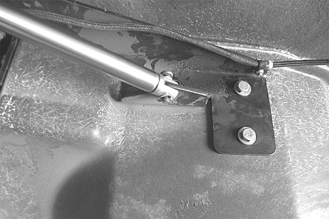
NOTE: If hood strut is not adjusted properly the hood will be damaged.
When a hood is removed and replaced an initial adjustment on the strut is necessary. Adjust between the top of the lift motor adjusting jam nut (1) to the top of the threads (2) to 20 mm (X). With the motor down to its lowest point take a measurement between the left hand side hood bumper and the counter weight, record this measurement (Y). Use the following table to adjust the strut (X).

Hood Adjustment Table
Y (MM) X (MM) Y (MM) X (MM) Y (MM) X (MM) Y (MM) X (MM)
1 19 21 14 41 9 61 5 2 19 22 14 42 9 62 5 3 18 23 14 43 9 63 4 4 18 24 13 44 9 64 4 5 18 25 13 45 9 65 4 6 18 26 13 46 8 66 4 7 17 27 13 47 8 67 3
8 17 28 12 48 8 68 3 9 17 29 12 49 8 69 3 10 17 30 12 50 7 70 3
11 16 31 12 51 7 71 2
12 16 32 12 52 7 72 2 13 16 33 11 53 7 73 2 14 16 34 11 54 6 74 2
15 16 35 11 55 6 75 2 16 15 36 11 56 6 76 1 17 15 37 10 57 6 77 1 18 15 38 10 58 6 78 1 19 15 39 10 59 5 79 1 20 14 40 10 60 5 80 0
2000-16
STEP 76
STEP 79
STEP 85
BD02N160
Check and make sure that drain caps are tight.
STEP 80
Install a new oil filter on engine. Fill engine with 13.25 liters (14 U.S. quarts) of Case AKCELA Engine Oil (SAE 15W-40).
STEP 81
If hydraulic reservoir was drained, fill reservoir with 90.8 liters (24.0 U.S. gallons) of Case AKCELA Hy-Tran Ultra® fluid.
STEP 82
Fill engine coolant system with a solution of 50% Ethylene Glycol and 50% water. Cooling system capacity is 28.4 liters (30.0 U.S. quarts). Install the radiator cap. Fill the coolant reservoir up to the FULL mark on the reservoir.
STEP 83
Connect the batteries, install battery covers, put master disconnect switch in ON position.
STEP 84
Start engine and run the engine at low idle. Run the engine at operating temperature for approximately five minutes to completely mix the Ethylene Glycol and water. When the coolant is at operating temperature, stop the engine. When engine has cooled, check the coolant level at the reservoir.
WARNING: Hot coolant can spray out if radiator cap is removed. To remove radiator cap: Let system cool, turn to first notch, then wait until all pressure is released. Scalding can result from fast removal of radiator cap.
Lower the hood with the hood lift motor.
STEP 86
Put articulation lock in OPERATING position.
2000-17
BD06F108
RADIATOR
Removal
STEP 1
Park loader on level surface and lower bucket to ground. Apply parking brake and shut down engine.
STEP 2
BD03A040
Put articulation lock in LOCKED position.
STEP 3
Put master disconnect switch in OFF position.
STEP 4
BD03A120
Have another person raise and hold the side panel up into the raised position. Remove the two mounting screws for the side panel, remove the panel.

NOTE: Photo is of the oil cooler side of the machine, the procedure is the same.


STEP 5
BD06F128
Remove bolt and washer securing LH fender. Remove LH fender.
STEP 6
BD02N160
Put a 28.4 liter (30.0 U.S. quart) container below radiator drain. Remove radiator cap then remove cap and drain coolant into container. Install cap after coolant has drained. Install radiator cap.
STEP 7
BD03A109
Release catch and tilt air conditioning condenser core up to gain access to upper radiator hose.
2000-18