
Part number 47824875 1st edition English January 2015 SERVICE MANUAL Speedrower® 220 Speedrower® 260 Tier 4B (final) Self-Propelled Windrower
Link Product / Engine
Product Market Product Engine
Speedrower® 220 North America
Speedrower® 260 North America
F4HFE613A*B001
F4HFE613A*B001
47824875 19/01/2015
INTRODUCTION
Engine . . . . . . . . . . . . . . . . . . . . . . . . . . . . . . . . . . . . . . . . . . . . . . . . . . . . . . . . . . . . . . . . . . . . . . . . . . . . . . . . . . . . . . .
[10.001] Engine and crankcase . . . . . . . . . . . . . . . . . . . . . . . . . . . . . . . . . . . . . . . . . . . . . . . . . . . . . . . . . . . . . 10.1
[10.202] Air cleaners and lines . . . . . . . . . . . . . . . . . . . . . . . . . . . . . . . . . . . . . . . . . . . . . . . . . . . . . . . . . . . . . . 10.2
[10.206] Fuel filters . . . . . . . . . . . . . . . . . . . . . . . . . . . . . . . . . . . . . . . . . . . . . . . . . . . . . . . . . . . . . . . . . . . . . . . . . . 10.3 [10.216] Fuel tanks . . . . . . . . . . . . . . . . . . . . . . . . . . . . . . . . . . . . . . . . . . . . . . . . . . . . . . . . . . . . . . . . . . . . . . . . . . 10.4 Fuel injection system [10.254] Intake and exhaust manifolds and muf fler . . . . . . . . . . . . . . . . . . . . . . . . . . . . . . . . . . . . . . . . . 10.6 [10.310] Aftercooler . . . . . . . . . . . . . . . . . . . . . . . . . . . . . . . . . . . . . . . . . . . . . . . . . . . . . . . . . . . . . . . . . . . . . . . . . . 10.7 Engine cooling system Fan and drive
Front axle system . . . . . . . . . . . . . . . . . . . . . . . . . . . . . . . . . . . . . . . . . . . . . . . . . . . . . . . . . . . . . . . . . . . . . . .
. . . . . . . . . . . . . . . . . . . . . . . . . . . . . . . . . . . . . . . . . . . . . . . . . . . . . . . . . . . . . . . . . . . . . . . . . 25.1 Rear
Contents
Selective Catalytic Reduction (SCR) exhaust treatment T ransmission . . . . . . . . . . . . . . . . . . . . . . . . . . . . . . . . . . . . . . . . . . . . . . . . . . . . . . . . . . . . . . . . . . . . . . . . . . . . . . Hydraulic pump drive
[25.310] Final drives
[27.550] Non-powered rear axle
. 27.1 Hydrostatic drive . . . . . . . . . . . . . . . . . . . . . . . . . . . . . . . . . . . . . . . . .
. . . T ransmission and steering hydrostatic control Hydrostatic transmission Pump and motor components Brakes and controls . . . . . . . . . . . . . . . . . . . . . . . . . . . . . . . . . . . . . . . . . . . . . . . . . . . . . . . . . . . . . . . . . . . . [33.1 10] Parking brake parking lock . . . . . . . . . . . . . . . . . . . . . . . . . . . . . . . . . . . . . . . . . . . . . . . . . . . . . . 33.1 Hydraulic systems . . . . . . . . . . . . . . . . . . . . . . . . . . . . . . . . . . . . . . . . . . . . . . . . . . . . . . . . . . . . . . . . . . . . . . . Hydraulic systems 47824875 19/01/2015
axle system . . . . . . . . . . . . . . . . . . . . . . . . . . . . . . . . . . . . . . . . . . . . . . . . . . . . . . . . . . . . . . . . . . . . . . . .
. . . . . . . . . . . . . . . . . . . . . . . . . . . . . . . . . . . . . . . . . . . . . . . . . . . . . . . . . . . .
. . . . . . . . . . . . . . . . . . . . . . . . . . . . .
Main lift system
[35.105] Charge pump . . . . . . . . . . . . . . . . . . . . . . . . . . . . . . . . . . . . . . . . . . . . . . . . . . . . . . . . . . . . . . . . . . . . . . . 35.3
[35.304] Combination pump units . . . . . . . . . . . . . . . . . . . . . . . . . . . . . . . . . . . . . . . . . . . . . . . . . . . . . . . . . . . 35.4
[35.415] Header attachment tilting system . . . . . . . . . . . . . . . . . . . . . . . . . . . . . . . . . . . . . . . . . . . . . . . 35.5
Steering . . . . . . . . . . . . . . . . . . . . . . . . . . . . . . . . . . . . . . . . . . . . . . . . . . . . . . . . . . . . . . . . . . . . . . . . . . . . . . . . . . . . .
Steering control
Cab climate control
. . . . . . . . 50.1
Electrical systems . . . . . . . . . . . . . . . . . . . . . . . . . . . . . . . . . . . . . . . . . . . . . . . . . . . . . . . . . . . . . . . . . . . . . . . Electrical system Hydrostatic drive control system Harnesses and connectors Electronic modules
F
AUL T CODES
Platform, cab, bodywork, and decals . . . . . . . . . . . . . . . . . . . . . . . . . . . . . . . . . . . . . . . . . . . . . operator seat [90.150] Cab . . . . . . . . . . . . . . . . . . . . . . . . . . . . . . . . . . . . . . . . . . . . . . . . . . . . . . . . . . . . . . . . . . . . . . . . . . . . . . . . . 90.2 [90.151] Cab interior . . . . . . . . . . . . . . . . . . . . . . . . . . . . . . . . . . . . . . . . . . . . . . . . . . . . . . . . . . . . . . . . . . . . . . . . . 90.3 [90.154] Cab doors and hatches . . . . . . . . . . . . . . . . . . . . . . . . . . . . . . . . . . . . . . . . . . . . . . . . . . . . . . . . . . . . 90.4
. . . . . . . . . . . . . . . . . . . . . . . . . . . . . . . . . . . . . . . . . . . . . . . . . . . . . . . . . . . . . . . . . . . . . [50.200] Air conditioning . . . . . . . . . . . . . . . . . . . . . . . . . . . . . . . . . . . . . . . . . . . . . . . . . . . . . . . . . . . . .
47824875 19/01/2015

47824875 19/01/2015 1
INTRODUCTION
Safety rules
Personal safety
This the safety alert used alert you potential personal injury Obey all safety messages that follow this symbol avoid possible death injury .

Throughout this manual you will find the signal words W and CAUTION followed special These precautions are intended for the personal safety you and those working with
Read and understand all the safety messages this manual before you operate service the
DANGER indicates a hazardous situation not will result death serious injury
W ARNING indicates a hazardous situation not could result death serious injury
CAUTION indicates a hazardous situation that, not avoided, could result minor moderate injury .
AILURE T O FOLLOW DANGER, W ARNING, AND CAUTION MESSAGES COULD RESUL T DEA SERIOUS INJUR Y .
Machine safety
NOTICE: Notice indicates a situation not could result machine property
Throughout this manual you will find the signal word Notice followed special instructions prevent machine property The word Notice used address practices not related personal safety
Information
NOTE: Note indicates additional information that clarifies other information this
Throughout this manual you will find the word Note followed additional information about a other information the The word Note not intended address personal safety property
INTRODUCTION
Series
F
47824875 19/01/2015 5
Safety rules
General safety rules
Use caution when operating the machine slopes. Raised equipment, full tanks and other loads will change the center gravity the The machine can tip roll over when near ditches and embankments uneven

• Only skilled operators who are familiar with all the controls and harvesting techniques should use the recommended operate cultivated land with slopes greater than % ( ° ) uphill and
• necessary , when driving downhill change into a lower gear before starting the Machine must stopped downshift into a lower gear
Never permit anyone other than the operator ride the Never operate the machine under the influence while otherwise
Pay attention overhead power lines and hanging High voltage lines may require significant clearance for safety
Hydraulic oil diesel fuel leaking under pressure can penetrate the causing serious injury
• NOT use your hand check for Use a piece cardboard paper
• Stop remove key and relieve the pressure before connecting disconnecting fluid
• Make sure all components are good condition and tighten all connections before starting the engine izing the system.
• hydraulic fluid diesel fuel penetrates the seek medical attention immediately
• Continuous long term contact with hydraulic fluid may cause skin cancer . A void long term contact and wash the skin promptly with soap and water Keep clear moving Loose jewelry , long hair , and other loose hanging items can become entangled moving
W ear protective equipment when NOT attempt remove material from any part the machine while being operated components are
Make sure all guards and shields are good condition and properly installed before operating the Never operate the machine with shields Always close access doors panels before operating the Dirty slippery and platforms can cause Make sure these surfaces remain clean and clear
A person pet within the operating area a machine can struck crushed the machine its NOT allow anyone enter the work
Raised equipment and / loads can fall unexpectedly and crush persons
Never allow anyone enter the area underneath raised equipment during
Never operate engine enclosed spaces harmful exhaust gases may build
Before starting the sure that all controls are neutral park lock
Start the engine only from the operator ’ s the safety start switch bypassed, the engine can start with the transmission gear not connect short across terminals the starter Attach jumper cables described the manual. Starting gear may cause death serious injury .
Always keep all and Slow Moving V ehicle (SMV) emblem clean provide the best possible visibility while operating the machine.
INTRODUCTION
47824875 19/01/2015 6
Operate controls only when seated the operator ’ s except for those controls expressly intended for use from other

Before leaving the machine: Park machine a firm level Put all controls neutral park lock Engage park use wheel chocks Lower all hydraulic equipment header , T urn f engine and remove key due exceptional you would decide keep the engine running after leaving the operator ’ s then the following precautions must followed: Bring the engine low idle Disengage all drive W ARNING Some components may continue run down after disengaging drive systems. Make sure all drive systems are fully Failure comply could result death serious injury .
Shift the transmission into Apply the parking General maintenance safety Keep area used for servicing the machine clean and dry Clean spilled Service machine a firm level surface. Install guards and shields after servicing the Close all access doors and install all panels after servicing the not attempt clear obstructions make adjustments the machine while motion while the engine Always make sure working area clear other persons and pets before you start operating the Unsupported hydraulic cylinders can lose pressure and drop the equipment causing a crushing not leave equipment a raised position while parked during unless securely Jack lift the machine only jack lift points indicated this Incorrect towing procedures can cause When towing a disabled machine follow the procedure this Use only rigid tow Stop the remove key and relieve pressure before disconnecting connecting fluid Stop the engine and remove key before disconnecting connecting electrical Scalding can result from incorrect removal coolant Cooling system operates under Hot coolant can spray out a cap removed while the system Allow system cool before removing When removing a cap turn slowly allow pressure escape before completely removing the Replace damaged worn tubes, electrical exhaust and hydraulic lines may become hot during T ake care when servicing such components. Allow surfaces cool before handling disconnecting hot components. W ear protective equipment when
INTRODUCTION
W01 13A
47824875 19/01/2015 7
Engine and crankcase - Overview
76075199 1
The NEF T ier engine a 6–cylinder turbocharged and after cooled unit, having a bore 104 ( 4.4 ) and a stroke 132 ( 5.0 ) which generates a displacement 410 in³ .

The engine uses a electronically controlled - pressure injection pump and has been designed meet current emission regulations and must only serviced authorized service agent.
All engines fearure cross flow cylinder heads, with the inlet and exhaust manifolds opposite sides the cylinder The fuel and air combustion takes place the specially designed bowl the crown the pistons.
NOTE: The FRONT the engine the water pump end. The REAR the engine the flywheel end. this section, right and left correspond the above when standing the rear the engine looking the flywheel end with the water pump end away from
Cylinder block assembly
The cylinder block alloy cast iron with deep cylinder and water jackets for cooling the The cylinder bores are machined integral with the cylinder during the manufacturing
Cylinders are line and vertical and numbered 1 6 from the front (fan end) the rear the engine. They can bored oversize for the fitment which are available
the following procedures and illustrations the engine shown removed from the vehicle however there are certain operations that can performed with the engine Where necessary remove the engine use a suitable hoist overhead gantry and standard engineering Removal the engine described Chapter 1 Section this Dismantle the engine following conventional techniques and referring the appropriate overhaul sections this chapter Always refer the specification section necessary
NOTE: Where necessary remove additional items gain access the components the engine refer Engine
Engine - Engine and crankcase
47824875 19/01/2015 10.1 [10.001] / 3
Engine and crankcase - Check fluid level
NOTE: Before checking the engine oil level, park the windrower a level surface, stop the engine, set the park and wait for a short period (minimum 5 minutes) allow the oil drain back into the oil
Clean the dipstick area debris and remove dipstick (1) wipe and reinsert fully
Pull the dipstick out again and check the oil The oil level should the top the flattened
NOTICE: not operate the engine with the oil level below the mark the Damage the engine may occur .


Adding engine oil
Clean any debris from around the crankcase fill cap (1) the left side the windrower
Remove the fill cap (1) and add oil required the level within the two marks the The quantity oil represented the upper and lower marks approximately 2 l ( 2.1 ) .
Install the fill cap and check the
NOTICE: not operate the engine with the oil level above the mark. The excess oil will burned off pushed out the crankcase breather and give a false pression oil
Engine - Engine and crankcase
NHIL14WR00297AA 1
NHIL14WR00293AA 2 47824875 19/01/2015 10.1 [10.001] / 5
Engine and crankcase - Drain fluid


W arn the engine operating Park the windrower a level surface centering the steering Set the parking Stop the
NOTICE: Clean the area around each check fill before Failure clean these areas may allow contamination enter the
Remove engine oil drain plug (1) and catch the oil a suitable container .
NOTE: the oil drains slowly , may help unscrew the filler cap for the engine
Replace the drain plug after the oil has been
Clean the oil filter
Unscrew and discard the oil filter (1)
NOTE: Always discard used oil and filters properly
Engine - Engine and crankcase
NHIL13WR001 14AA 1
47824875 19/01/2015 10.1 [10.001] / 6
NHIL14WR00296AA 2
Engine and crankcase - Filling
Apply a thin film clean oil around the rubber seal the new oil filter . Screw the new filter onto the filter head until the rubber seal contacts the mounting then tighten additional 3 / 4 1 full not
Clean any debris from around the crankcase fill cap. Remove the filler cap (1) and fill the engine with proximately l ( 16.9 ) fresh adhering the correct grade and viscosity
Start and run the engine idle speed for approximately one minute circulate the then stop the
NOTICE: V erify the engine oil pressure the operating range start stop the engine and investigate the cause, serious engine damage will
Check the drain plug and oil filter areas for
W ait five allow the oil drain into the oil and recheck the oil level the The oil level should between the two
add more oil obtain the correct
NOTICE: not operate engine with the oil level below the lower notch the Damage the engine may occur
NOTICE: The use B20 fuel requires checking the engine oil daily
Engine - Engine and crankcase
NHIL14WR00293AA 1 47824875 19/01/2015 10.1 [10.001] / 7
Engine - Remove - NEF 6 cylinder
Speedrower® 220
Speedrower® 260
Draper ready - Factory - fitted accept draper - - - Non draper ready - Not fitted for draper header
Draper ready - Factory - fitted accept draper - - - Non draper ready - Not fitted for draper header
Remove bolt (2) starter disconnect ground cable and the negative battery
Remove battery post nut and disconnect positive tery cable (3)
Remove protective cap and disconnect all cables from starter solenoid (1)
NHIL13WR001 12AA 1
Disconnect cable and two wires (1) from alternator (2) Remove complete wire harness from engine


NHIL13WR00108AA 2
Drain coolant from radiator and engine opening valve (1) . Catch fluid from drain hose and save for Remove the radiator cap speed the using caution the system
Disconnect drain hose.
NHIL14WR00316AA 3
Engine - Engine and crankcase
47824875 19/01/2015 10.1 [10.001] / 8
Remove the spring clamp (1) remove the exhaust pipe elbow (2) from the turbocharger
NHIL14WR01 144AA 4
Using a helper , detach four gas springs (1) from engine area side doors removing four flange nuts and lock
NHIL14WR01 151AA 5
Remove side doors removing bolts (1) and lifting doors upward f the support brackets.
NOTICE: Figure 6 shows a top view the support not stand top the engine


Remove four carriage lock washers and flange nuts (5) that secure the front the hood.
NHIL14WR01 152AA 6
Engine - Engine and crankcase
47824875 19/01/2015 10.1 [10.001] / 9
1 Loosen the spring clamps (1) and remove tubing from turbo intercooler (2) , and from intercooler intake manifold (3)
NHIL14WR01 138AA 7
NHIL14WR01 145AA 8
Disconnect restriction indicator switch (1)
NHIL14WR01 138AA 9
Loosen clamps and remove 127 ( 5 ) diameter outlet tubing (1) from air cleaner the turbocharger


NHIL14WR01 137AA

Engine - Engine and crankcase
47824875 19/01/2015 10.1 [10.001] /
14. T ag, label, and disconnect all harnesses (1) that connect the electrical system the frame the windrower the center roof section the windrower

15. Remove all cable ties holding the large harness the center roof

NHIL14WR01 149AA 1 1
Squeeze the tabs and disconnect the DEF / A D B LUE ® lines (1) that connect the supply module the dosing
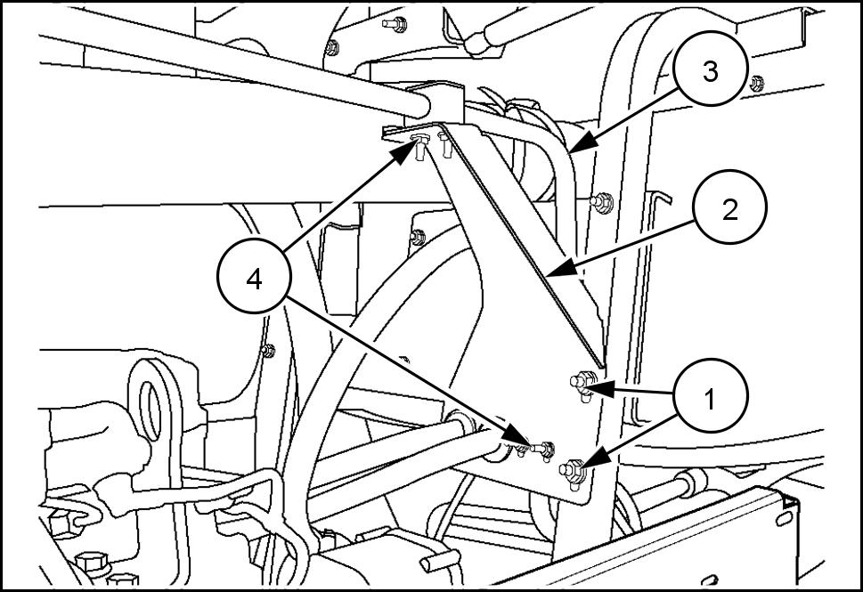
Remove flange lock washers and flange nuts (1) , detach hood support frame from radiator side supports and from front

Use suitable slings lift the hood support roof and exhaust after - treatment from the
NHIL14WR01 148AA
NHIL14WR01 146AA
NHIL14WR01 147AA
Engine - Engine and crankcase
47824875 19/01/2015 10.1 [10.001] / 1 1
NOTICE: Use jackstands support the hood support frame that the Selective Catalytic Reduction (SCR) components not get damaged when setting the hood


NHIL14WR01 124AA
Disconnect wire harness (1) from A / C compressor (2)


NHIL14WR01 145AA
Disconnect ECM harness (1) Remove ECM harness and A / C compressor harness from the 21. Remove and cap fuel lines (2) . 76075209 Remove and cap both heater hoses (1)
NHIL14WR01 150F A
Engine - Engine and crankcase
47824875 19/01/2015 10.1 [10.001] /
23.
Remove clamps (1) that secure A / C compressor line (2)
Remove flange nuts (3) that secure bracket (4) Set bracket and heater hoses aside.
76075210
Remove air hose (1) that lead crankcase ventilation 76075210
Remove A / C compressor drive belt releasing tension tensioner (1) 86070777

Remove three bolts (1) that secure A / C compressor Hang compressor right side machine (2) with hoses

NOTICE: Use caution when hanging compressor (2) sure not damage bend any the steel fluid equipped with optional hydraulic pump (1) remove two bolts and lay this pump over right Disconnect wire harness from fuel water switch (2)


Engine - Engine and crankcase
NHIL WR00594AA 47824875 19/01/2015 10.1 [10.001] /
30. Disconnect both upper and lower radiator hoses (1) .


76077320
Loosen clamp bolts (1) steering yoke and remove from splined shaft steering motor
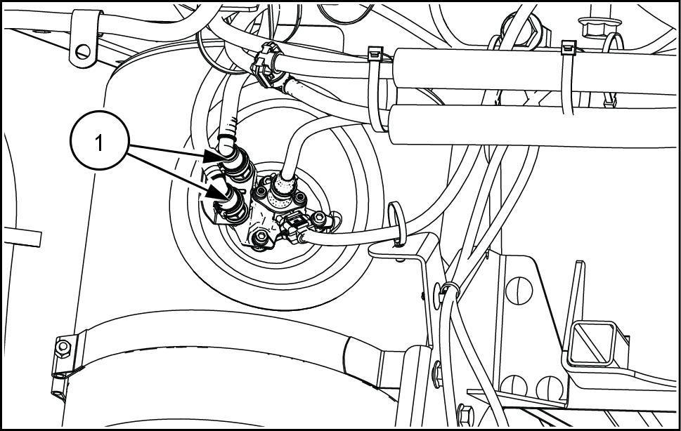
Remove and cap steel hydraulic lines (1) the top Use a collection pan catch any excess fluid that may Disconnect breather hose (2) 86070789
Remove plug (1) drain oil from gear
With adequate support provided for the move flange bolts (2) that secure the pumps cover plate (3)
With adequate support provided for the fully move transmission and header drive pump away from 76077321
Engine - Engine and crankcase
NHIL13WR00104AA
47824875 19/01/2015 10.1 [10.001] /
36. Remove four flange screws and lock washers (1) from radiator side fan and detach from drive Set fan rearward fan shroud give maximum clearance lift out 50050774


37. Remove four large cap screws with lock nuts (1) . 38. Use appropriate lifting equipment lift engine out
Mount the engine engine stand before removing the chain and hoist. 76075209
Engine - Engine and crankcase
47824875 19/01/2015 10.1 [10.001] /


Engine - Engine and crankcase
- Install - NEF 6 Cylinder
220
Support
component(s)
W1024A
47824875 19/01/2015 10.1 [10.001] /
Engine
Speedrower®
Draper ready - Factory - fitted accept draper - - - Non draper ready - Not fitted for draper header Speedrower® 260 Draper ready - Factory - fitted accept draper - - - Non draper ready - Not fitted for draper header W ARNING Heavy parts!
designated
with adequate lifting equipment. Failure comply could result death serious injury
Align holes engine supports and install four 5 / 8 x / 2 bolts with large washers (1) down through gine mounts and install lock T ighten 149 N·m ( 1 ) 76075209 1 Install four flange bolts and lock washers (1) from radiator side fan and attach drive sheave. 50050774 2 With adequate support provided for the carefully move transmission and header drive pump into mounting Install all flange bolts (1) that cure the pumps cover plate (2) NOTE: Use L OCTITE ® 598™ B LACK silicon sealant ing surfaces before joining pumps cover Install and tighten drain plug (3) cover 76077321 3

Thank you very much for your reading. Please Click Here. Then Get COMPLETE MANUAL.NOWAITING NOTE: If there is no response to click on the link above, please download the PDF document first and then clickonit.
Fill front gear case section flywheel housing moving breather plug (1) with l ( ) NEW HOLLAND AMBRA HYPOIDE NEW HOLLAND AMBRA HYPOIDE SSL GEAR OIL Oil level should between the two marks the dipstick (2)
Replace breather (1) 86070789 4
Install steel hydraulic lines (1) the top Attach breather hose (2) 86070789 5
Attach steering yoke (1) splined shaft (2) T ighten clamp bolts (3) 10041 124 6
Connect and tighten both upper and lower radiator hoses (1) equipped with optional hydraulic pump (1) install two 3 / 8 x / 2 socket head bolts and lock washers (2) that secure


1 Connect wire harness fuel water switch (3)

Engine - Engine and crankcase
47824875 19/01/2015 10.1 [10.001] /
76077320 7
12. Install and tighten 5 / in. x 4 in. bolts (1) through the base A / C compressor
Install and adjust A / C compressor drive belt (1) adjusting tension tensioner (2) . 86070777 9


Attach air hose (1) that leads crankcase ventilation 76075210
Install flange flange and lock washers (1) that secure bracket (2) . Secure A / C compressor line (3) with clamps (4)
Engine - Engine and crankcase
NHIL WR00594AA 8
76075210 1 1 47824875 19/01/2015 10.1 [10.001] /
Connect both heater hoses (1) .
Connect ECM harness (1) 18. Connect both inlet and return fuel lines (2) . 76075209 19. Connect wire harness (1) A / C compressor (2) .
Arrange wiring harness around engine original and install clamps position protect harness from damage operation. 21. Use suitable slings lift the hood support frame into place over the T ake care not damage any Selective Catalytic Reduction (SCR) components while moving the frame into

Engine - Engine and crankcase
16.
NHIL14WR01
150F A
NHIL14WR01
47824875 19/01/2015 10.1 [10.001] /
145AA