Service
Previous Screen
Product: EXCAVATOR
Model: 311B EXCAVATOR 8GR
Configuration: 311B TRACK-TYPE EXCAVATORS 8GR00001-UP (MACHINE) POWERED BY 3064 ENGINE
Disassembly and Assembly
311B, 312B & 312B L EXCAVATORS MACHINE SYSTEMS
Travel Motor & Final Drive
SMCS - 4050-010; 4050-017; 4351-010; 4351-017
Remove & Install Travel Motor & Final Drives
Start By:
a. separate track assemblies

b. remove sprocket
Fluid Spillage Containment
Care must be taken to ensure that the fluids are contained during performance of the inspection, the maintenance, the testing, the adjusting and the repair of the machine. Be prepared to collect the fluid with suitable containers before opening any compartment or disassembling of the any components containing fluids. Refer to the "Tools And Shop Products Guide", NENG2500 for the tools and the supplies suitable to collect and contain any of the fluids in Caterpillar machines. Dispose of the fluids according to local regulations and mandates.
At operating temperature, the hydraulic oil tank is hot and under pressure. Hot oil can cause burns. To prevent possible personal injury, release the pressure in the implement hydraulic circuits (the boom, the stick and the bucket) before any of the hydraulic lines or any of the components are disconnected or removed.
1. Release the pressure the implement hydraulic circuits (the boom, the stick and the bucket) before any of the hydraulic lines or any of the components are disconnected or removed. Release the pressure as follows:
a. Shut off the engine and place key in the "ON" position. Put the hydraulic activation control lever in the "UNLOCK" position.
b. Move the control levers for the boom, the stick, and the swing to all full stroke positions. This will release any pressure that might be present in the pilot system.
c. Return the key to "OFF" position.
d. Slowly loosen the fill plug on the hydraulic tank, and release the pressure.
e. Tighten the fill plug on the hydraulic tank.
f. The pressure in the hydraulic system has been released, the lines and the components can be removed
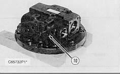
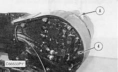
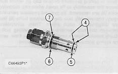
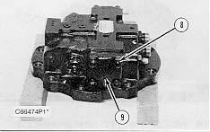
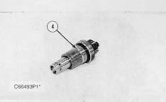
2. Remove access cover assembly (1) from over the rear side of the final drive.
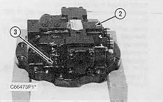
3. Disconnect hose assemblies (2) and (3) from the travel motor. Put plugs in the hose assemblies to keep dirt and debris out of the hydraulic system.
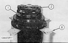
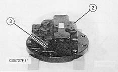
4. Fasten Tooling (A) and a hoist to final drive. Put slight lifting tension on the final drive with the hoist.
5. Remove 16 bolts (4) that hold the travel motor and the final drive to the undercarriage frame assembly. Remove the travel motor and the final drive. The weight of the travel motor and the final drive is approximately 160 kg (352 lb).
NOTE: The following steps are for the installation of the final drive.
6. Make sure the mating surfaces of the travel motor, the final drive and the undercarriage frame assembly are clean and free of dirt and debris.
7. Check the condition of the O-ring seals in the ends of hose assemblies (2) and (3). If any of the seals are worn or damaged, use new parts for replacement.
8. Fasten Tooling (A) and a hoist to travel motor and the final drive and put it in position in the undercarriage frame assembly. Make sure all mounting bolt holes are in alignment.
9. Put a thin coat of 9S-3263 Thread Lock on threads of sixteen bolts (4). Install sixteen bolts (4) that hold the final drive to the undercarriage frame assembly. Tighten the bolts evenly.
10. Connect hose assemblies (2) and (3) to the travel motor.
11. Reinstall the access cover assembly over the rear of the final drive.
NOTE: Refer to the topic "Lubricant Viscosities and Refill Capacities" in the "Operation & Maintenance Manual" for the proper filling procedure and the proper levels for the hydraulic oil system.
12. Check the oil level in the hydraulic tank. If necessary, fill it to the correct level.
End By:
a. install sprocket
b. connect track assemblies
Disassemble & Assemble Travel Motor & Final Drives (312B Excavator)
Start By:
a. remove travel motor and final drive
1. Thoroughly clean the outside of the travel motor and the final drive prior to disassembly.
2. Put an alignment mark across the sections of the travel motor and the final drive for assembly purposes. The parts must be reinstalled in their original locations.

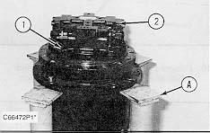
3. Fasten the travel motor and the final drive to Tooling (A) as shown. Remove the drain plug to drain the oil. The capacity of the 312B final drive is 2.5 liters (.6 U.S. gal).
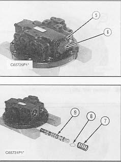
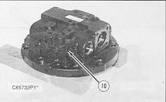
4. Remove ten bolts (1) and travel brake valve (2).
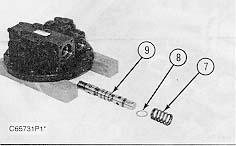
5. Position travel brake valve (2) on wood blocks as shown. Remove relief valve (3).
6. Remove back-up rings (4), O-ring seal (5), O-ring seal (6) and back-up ring (7) from the relief valve.
There is spring pressure behind cap (9) which may cause the assembly to fly apart when cap mounting bolts (8) are removed. To prevent possible personal injury, remove only two cap mounting bolts (8) that are diagonal to each other. Then, alternating between the two remaining cap mounting bolts, slowly loosen them a small amount at a time, until the spring pressure is completely released.

1. Remove two cap mounting bolts (8) that are diagonal to each other. Then, alternating between the two remaining cap mounting bolt, slowly loosen them a small amount at a time, until the spring pressure is released. Remove cap (9) from the travel brake valve.
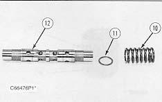
NOTE: Spool assembly (12) should not be disassembled. That component is serviced as an assembly.
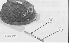
8. Remove spring (10), washer (11) and spool assembly (12) from the travel brake valve.


 9. Remove plug (13) and O-ring seal (14) from the travel brake valve. Remove the O-ring seal from plug (13).
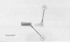
10. Remove plunger (15) and spring (16) located behind plug (13), from the travel brake valve.
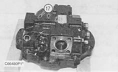
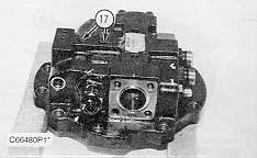
11. Remove two plugs (17).
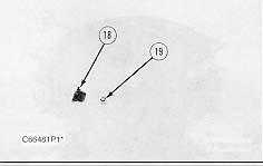
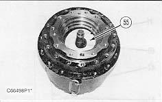
12. Remove O-ring seal (18) from each plug. Remove ball (19) from the travel brake valve.
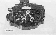
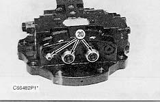
13. Remove three hose fittings (20). Remove all of the O-ring seals from hose fittings (20).
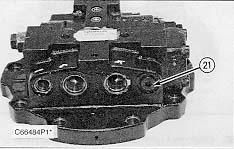
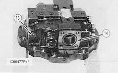
14. Remove plug (21) from the travel brake valve. Remove the O-ring seal from plug (21).
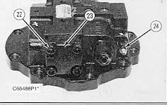
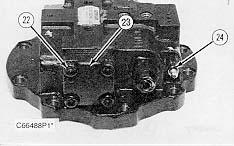
15. Remove four cap mounting bolts (22) and remove cap (23). Remove fitting (24). Remove the O-ring seal from fitting (24).
9. Remove plug (13) and O-ring seal (14) from the travel brake valve. Remove the O-ring seal from plug (13).
10. Remove plunger (15) and spring (16) located behind plug (13), from the travel brake valve.
11. Remove two plugs (17).
12. Remove O-ring seal (18) from each plug. Remove ball (19) from the travel brake valve.
13. Remove three hose fittings (20). Remove all of the O-ring seals from hose fittings (20).
14. Remove plug (21) from the travel brake valve. Remove the O-ring seal from plug (21).
15. Remove four cap mounting bolts (22) and remove cap (23). Remove fitting (24). Remove the O-ring seal from fitting (24).
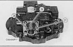

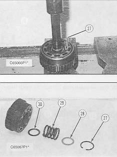
 16. Remove spring (25) and washer (26) from the travel brake valve. Remove O-ring seal (27) from the valve body.
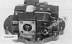
17. Remove relief valve (28) from the valve body.
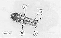
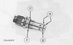
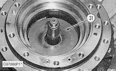
18. Remove back-up rings (29), O-ring seal (30), O-ring seal (31) and back-up ring (32) from the relief valve.
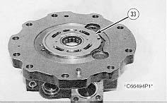
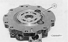
19. Reposition the travel brake valve body as shown. Remove plate (33) from the body.
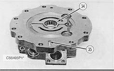
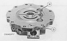
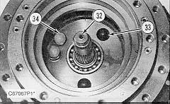
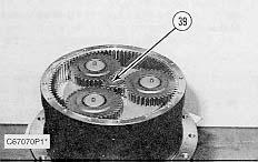
20. If necessary, remove bearing (34) and location pin (35).
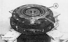
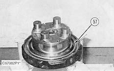
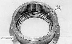
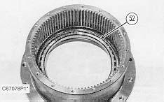
21. Remove three O-ring seals (36) and washer set (37) from the travel motor body.
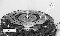
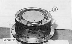
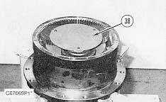
22. Remove shim (38).
16. Remove spring (25) and washer (26) from the travel brake valve. Remove O-ring seal (27) from the valve body.
17. Remove relief valve (28) from the valve body.
18. Remove back-up rings (29), O-ring seal (30), O-ring seal (31) and back-up ring (32) from the relief valve.
19. Reposition the travel brake valve body as shown. Remove plate (33) from the body.
20. If necessary, remove bearing (34) and location pin (35).
21. Remove three O-ring seals (36) and washer set (37) from the travel motor body.
22. Remove shim (38).
23. Install Tooling (B) as shown.
a. While retaining brake piston (39) with Tooling (B) apply shop air pressure (free of water) of approximately 525 kPa (75 psi) to brake release port (Y).
b. Brake piston (39) will move up and out of the travel motor body.
c. Remove brake piston (39) from the travel motor body.
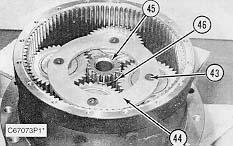
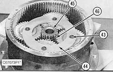
24. Remove O-ring seals (40) and (42) and back-up rings (41) and (43) from the brake piston.
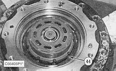
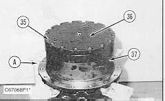
25. Remove two friction plates and two steel plates (44) from the travel motor body.

NOTICE
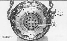
Do not let the components of barrel assembly (45) come apart during the removal from the travel motor body. All of the components in the barrel assembly must be reinstalled in their original locations.
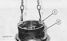
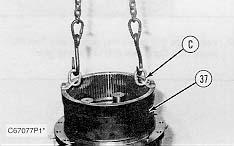
26. Fasten Tooling (C) and position the travel motor and the final drive as shown. Remove barrel assembly (45) from the travel motor body.
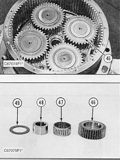
27. Shoe retainer (46) and piston shoe assemblies (47) are not serviced separately. Prior to removal of the shoe retainer and the piston shoe assemblies from barrel (48), put identification marks on piston shoe assemblies (47) as to their location in shoe retainer (46) and barrel (48). The piston shoe assemblies must be reinstalled in their original bores in the shoe retainer and the barrel.
28. Remove shoe retainer (46) and piston shoe assemblies (47) from barrel (48). Separate the piston shoe assemblies from the shoe retainer.
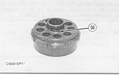
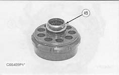
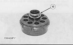
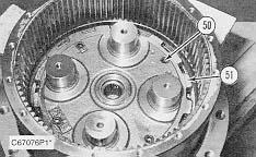
29. Remove bushing (49) from the barrel.
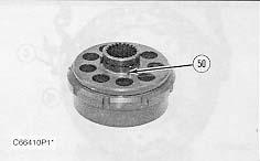
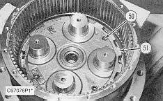
30. Remove three pins (50) from the barrel.
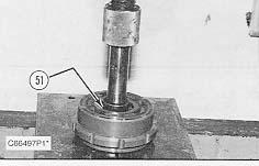
There is spring force against washer (52). When snap ring (51) is removed, the spring force will be released. To prevent possible personal injury, removal of the internal components in barrel (48) should be performed in a press in order to retain spring (53) and washer (52).
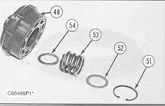
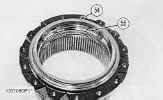
31. Put barrel (48) in a press. Install a suitable size drive plate that is slightly smaller in diameter than washer (52), on washer (52). Put a slightly amount of compression on washer (52) with the press. Remove snap ring (51) and slowly release the spring compression. Remove washer (52), spring (53) and washer (54) from the barrel (48).
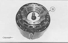
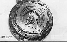
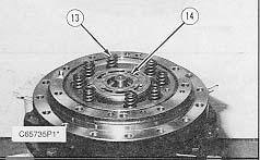
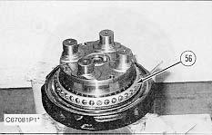
32. Remove cam plate (55) from the travel motor body.
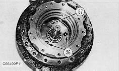
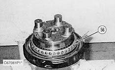
 33. Put identification marks on two balls (56) and piston (57) as to their location in the travel motor body. Remove two balls (56) and piston (57) from the travel motor body. Remove the spring located behind the piston.
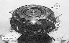
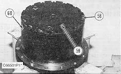
34. Fasten the final drive to Tooling (A) as shown. Remove sixteen bolts (58) and the washers that hold cover (59) in place.


 35. Using a soft faced hammer, break the seal between cover (59) and ring gear (60). Remove the cover.
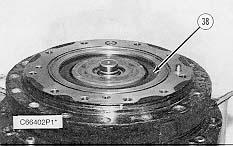
36. Remove washer (61) and three bolts (62) and plate (63).
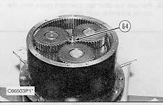
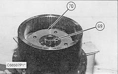
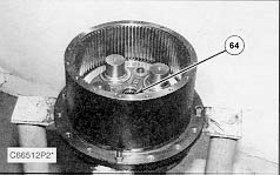
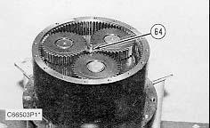
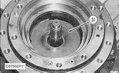
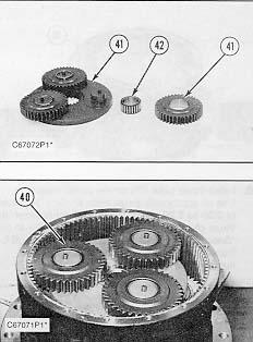
37. Remove sun gear (64) from the carrier assembly.
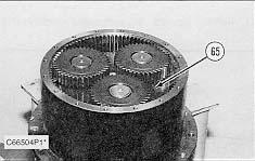
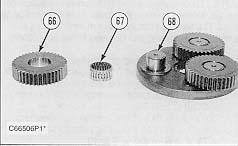
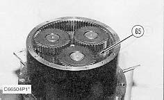
38. Remove carrier assembly (65) by lifting it straight up.
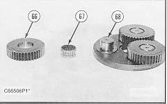
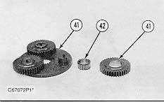
39. Remove planetary gear (66) and bearing (67) from the carrier assembly. If necessary, remove race (68) from the carrier assembly shaft.
40. Remove the other two planetary gears from the carrier assembly as in Step 39.
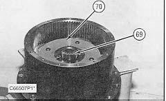
41. Remove sun gear (69) from carrier assembly (70).
35. Using a soft faced hammer, break the seal between cover (59) and ring gear (60). Remove the cover.
36. Remove washer (61) and three bolts (62) and plate (63).
37. Remove sun gear (64) from the carrier assembly.
38. Remove carrier assembly (65) by lifting it straight up.
39. Remove planetary gear (66) and bearing (67) from the carrier assembly. If necessary, remove race (68) from the carrier assembly shaft.
40. Remove the other two planetary gears from the carrier assembly as in Step 39.
41. Remove sun gear (69) from carrier assembly (70).
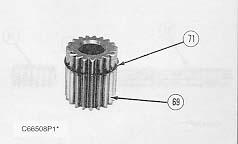
Remove retaining ring (71) from sun gear (68).


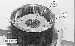 43. Remove four bolts (72) and plate (73).
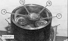
44. Remove planetary gear (74), bearing (75), race (76) and washer (77) from the carrier assembly. 45. Remove the other three planetary gears from the carrier assembly as in Step 44.
46. Remove bolt (78) from the planetary carrier.
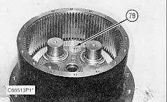
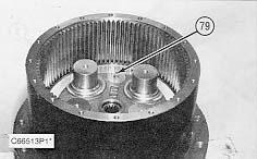
47. Use a magnet to remove pin (79).
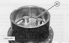
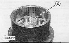
48. Remove nut (80) from the final drive housing.
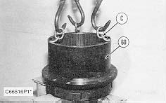
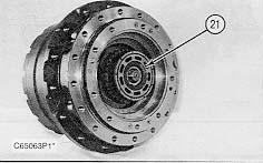
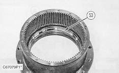
49. Fasten Tooling (C) and a hoist to ring gear (60) as shown. Remove the ring gear from the main housing.
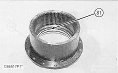
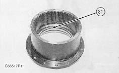
50. Remove bearing (81) from the ring gear.
43. Remove four bolts (72) and plate (73).
44. Remove planetary gear (74), bearing (75), race (76) and washer (77) from the carrier assembly. 45. Remove the other three planetary gears from the carrier assembly as in Step 44.
46. Remove bolt (78) from the planetary carrier.
47. Use a magnet to remove pin (79).
48. Remove nut (80) from the final drive housing.
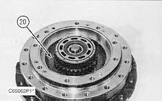
49. Fasten Tooling (C) and a hoist to ring gear (60) as shown. Remove the ring gear from the main housing.
50. Remove bearing (81) from the ring gear.
51. If necessary, remove race (82) from the ring gear.
52. Reposition the ring gear as shown. If necessary, remove race (83) from the ring gear.
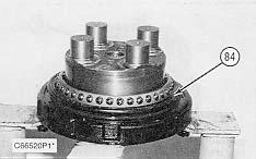
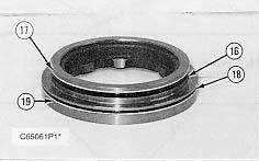
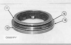
53. Remove Duo-Cone seal (84) from the main housing.
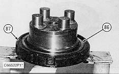
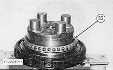
54. Remove bearing (85) from the main housing.
55. Remove Duo-Cone seal (86) from main housing (87).
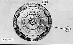
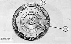
56. Reposition the main housing as shown. Remove shaft (88) from the main housing. Remove bearing (89) from the shaft.


NOTE: The following steps are for the assembly of the travel motor and the final drive.
57. Make sure all of the parts of the travel motor and the final drive are thoroughly clean and free of dirt and debris prior to assembly. Check the condition of all O-ring seals used in the travel motor and the final drive. If any of the seals are worn or damaged, use new parts for replacement. Reassemble the travel motor and the final drive on Tooling (A).
58. Put bearing (89) on shaft (88). Install shaft (88) into the main housing.
NOTICE
Refer to the topic "Assembly And Installation Of Conventional DuoCone Seals" in this module.
NOTE: The rubber seals and all of the surfaces that make contact with the seals must be clean and dry. After the installation of the seals, put clean SAE 30 weight oil on the contact surfaces of the metal seals.
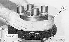
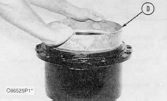
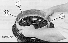
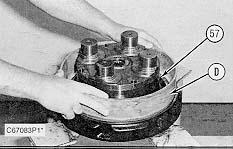
59. Using Tool (D), install Duo-Cone seal (86) in the main housing.
60. Install bearing (85) on the main housing.
61. Install race (83) to the ring gear.
62. Install race (82) to the ring gear.
63. Install bearing (81) to the ring gear.
NOTICE
Refer to the topic "Assembly And Installation Of Conventional DuoCone Seals" in this module.

NOTE: The rubber seals and all of the surfaces that make contact with the seals must be clean and dry. After the installation of the seals, put clean SAE 30 weight oil on the contact surfaces of the metal seals.
64. Using Tool (D), install Duo-Cone seal (84) in the main housing.
Do not scratch or damage the Duo-Cone seals in the main housing or the ring gear during assembly of these two components. After the installation of the ring gear on the main housing, there will be a small gap between the components. The gap is caused by the Duo-Cone seals and will be eliminated during the installation of nut (80).
66. Use the following procedure to make a preload adjustment of bearing (81) as follows:
a. Tighten nut (80) until there is no gap between main housing (87) and bearing (81).
b. Rotate ring gear (60) several turns.
c. Turn nut (80) in and/or out until the rotational torque of ring gear (60) is 21 ± 5 N·m (15 ± 4 lb

 65. Fasten Tooling (C) and a hoist to ring gear (60) as shown. Install the ring gear on the main housing.
ft).
67. Install pin (79) in nut (80).
68. Apply 9S-3263 Thread Lock to bolt (78). Install bolt (78) to the planetary carrier. Tighten the bolt to a torque of 69 ± 5 N·M (50 ± 4 lb ft).
69. Position the travel motor and the final drive housing as shown. Install two balls (56), the spring and piston (57) in the travel motor body.
65. Fasten Tooling (C) and a hoist to ring gear (60) as shown. Install the ring gear on the main housing.
ft).
67. Install pin (79) in nut (80).
68. Apply 9S-3263 Thread Lock to bolt (78). Install bolt (78) to the planetary carrier. Tighten the bolt to a torque of 69 ± 5 N·M (50 ± 4 lb ft).
69. Position the travel motor and the final drive housing as shown. Install two balls (56), the spring and piston (57) in the travel motor body.
70.
71. Install washer (54), spring (53) and washer (52) in barrel (48).


72.
73. Install three pins (50) in the barrel.
74.
75.
76.
Install cam plate (55) in the travel motor body. Make sure the machined cutouts in the cam plate engage with the balls and the piston. Use a press, and compress spring (53). Install retaining ring (51). Install bushing (49) to the barrel. Install piston shoe assemblies (47) in their original bores in shoe retainer (46). Put clean hydraulic oil in the bores of the barrel and on piston shoe assemblies (47). Install the piston shoe assemblies with the shoe retainer in their original bores in barrel (48). 77. Put clean hydraulic oil on the sliding surfaces of the cam plate, the piston shoe assemblies and on the splined shaft of the motor. Put the travel motor body on its side and install barrel assembly (45) on the shaft as a unit.78. Put clean hydraulic oil on two friction plates and two steel plates (44). Install the plates in alternating order in the travel motor body. Start with a friction plate and end with a steel plate.
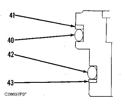
79. Make sure brake piston (39) is thoroughly clean and free of dirt and debris. Check the condition of back-up rings (41) and (43) and O-ring seals (40) and (42). If the rings or the seals are worn or damaged, use new parts for replacement. Install back-up rings (41) and (43) and O-ring seals (40) and (42) on brake piston (39) as shown. Put a coat of 1U-6396 Assembly Compound on the back-up rings and the O-ring seals.
80. Put a thin coat of clean hydraulic oil on the surface of the travel motor body which makes contact with piston (39). Install piston (39) in the travel motor body by hand. It may be necessary to use a soft faced hammer to seat the piston properly.
 81. Install shim (38) in the piston.
82. Install washer set (37) in the piston. Install three O-ring seals (36) in the travel motor body.
83. Install bearing (34) and location pin (35) in the travel brake valve.
81. Install shim (38) in the piston.
82. Install washer set (37) in the piston. Install three O-ring seals (36) in the travel motor body.
83. Install bearing (34) and location pin (35) in the travel brake valve.
84. Install plate (33) in its original position on the travel brake valve.

85. Install back-up ring (32) and O-ring seal (31) on the relief valve. Install back-up rings (29) and O-ring seal (30) on the relief valve as shown.
86. Install relief valve (28) in the travel brake valve body. Tighten the relief valve body to a torque of 200 ± 20 N·m (145 ± 15 lb ft).
87. Install washer (26) and spring (25) in the travel brake valve. Install O-ring seal (27) to the valve body.
88. Install cap (23) and four cap mounting bolts (22) that hold it. Tighten the bolts to a torque of 78 ± 8 N·m (60 ± 6 lb ft).
89. Put the O-ring seal on fitting (24) and install it in the travel brake valve body.
90. Put the O-ring seal on plug (21) and install it in the travel brake valve body. Tighten the plug to a torque of 69 ± 5 N·m (50 ± 4 lb ft).
91. Put the O-ring seals on fittings (20), and install them in the travel brake valve body.
92. Install two balls (19) in the travel brake valve body. Put O-ring seals (18) on plugs (17). Install the plugs to the travel brake valve. Tighten the plugs to a torque of 20 ± 2 N·m (15 ± 1 lb ft).
93. Put plunger (15) and spring (16) in the travel brake valve body. Put the O-ring seal on plug (13). Install plug (13) to the travel brake valve. Tighten the plug to a torque of 49 ± 5 N·m (36 ± 4 lb ft).
94. Put O-ring seal (14) on the travel brake valve body.
95. Install spring (10) and washer (11) in the valve body. Put a thin coat of clean hydraulic oil on spool assembly, and install it in the valve body.
NOTE: To compress spring (10) during installation of cap (9), longer cap mounting bolts must temporarily be used. The two travel brake valve mounting bolts are suitable in length and can be used in this application.
96. Temporarily install cap (9) with two longer mounting bolts. Tighten the two bolts evenly until the spring is compressed and the cap is against the valve body. Install two original cap mounting bolts (8) to hold the cap; then replace the temporary bolts with the original cap mounting bolts. Tighten cap mounting bolts (8) to a torque of 78 ± 8 N·m (60 ± 6 lb ft).

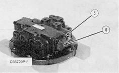
97. Install back-up ring (7) and O-ring seal (6) on the relief valve. Install back-up rings (4) and O-ring seal (5) on the relief valve as shown.
98. Install relief valve (3) to travel brake valve (2). Tighten the relief valve body to a torque of 200 ± 20 N·m (145 ± 15 lb ft).
99. Position travel brake valve (2) on the travel motor housing. Install ten bolts (1) that hold it. Tighten the bolts to a torque of 191 ± 15 N·m (140 ± 11 lb ft).
100. Reposition the travel motor and the final drive housing as shown. Install Sun Gear (64) to the final drive housing. Using Sun Gear (64), check to see if the motor output shaft can start rotating by a torque of 215 to 235 N·m (160 to 175 lb ft). If the motor output shaft does rotate within specification, continue with the assembly of the final drive. If the motor output shaft does not rotate within specification, shim (38) needs to be changed. Shim (38) are available in several different thicknesses. When necessary to increase torque, use a thicker shim. When necessary to decrease torque, use a thinner shim. Refer to the Specifications module, 311B, 312B and 312B L Excavators, Hydraulic Systems, for a list of shims that can be used.
101. Install all washers (77), races (76), bearings (75) and planetary gears (74) to the planetary carrier.
102. Put plate (73) on the carrier assembly. Apply 9S-3263 Thread Lock to bolts (72). Install four bolts (72) that hold plate (73) to the planetary carrier. Tighten the bolts to a torque of 69 ± 5 N·m (50 ± 4 lb ft).
103. Install retaining ring (71) to sun gear (69).
104. Install sun gear (69) in carrier assembly (70).
105. Install race (68) on the carrier shaft assembly. Put bearing (67) and planetary gear (66) on the carrier shaft assembly.

106. Install the other two planetary gears on the carrier assembly as in Step 105.
107. Install planetary carrier (65) in the final drive housing.
108. Install sun gear (64) in the carrier assembly.
109. Put plate (63) on the carrier assembly. Apply 9S-3263 Thread Lock to bolts (62). Install three bolts (62) that hold plate (63) to the planetary carrier. Tighten the bolts to a torque of 69 ± 5 N·m (50 ± 4 lb ft).
110. Install washer (61) on plate (63).
111. Make sure the machined surface of ring gear (60) and cover (59) is thoroughly clean, free of dirt and debris, and is dry. Put a bead of 1U-8846 Gasket Maker around the machined surface of the ring gear. Put cover (59) in its original position on the ring gear.
112. Install bolts (58) and the washers that hold the cover. Tighten the sixteen bolts to a torque of 35 ± 2 N·m (26 ± 1 lb ft).
NOTICE
To prevent possible damage to the travel motor, the unit should be filled at least up to the fill port prior to operation. Refer to the "Operation & Maintenance Manual" for the correct oil specification.
End By:
a. install travel motor and final drive
Disassemble & Assemble Travel Motor & Final Drives (311B Excavator)
Start By:
a. remove travel motor and final drive
1. Thoroughly clean the outside of the travel motor and the final drive prior to disassembly.
2. Put an alignment mark across the sections of the travel motor and the final drive for assembly purposes. The parts must be reinstalled in their original locations.

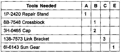
3. Fasten the travel motor and the final drive to Tooling (A) as shown. Remove the drain plug to drain the oil. The capacity of the 311B final drive is 2.6 liters (.7 U.S. gal).
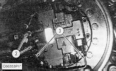
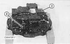
4. Remove nine bolts (1) and travel brake valve (2).
5. Position travel brake valve (2) on wood blocks as shown. Remove two relief valves (3).
6. Remove O-ring seal (4) from the relief valves.
There is spring pressure behind cap (6) which may cause the assembly to fly apart when cap mounting bolts (5) are removed. To prevent possible personal injury, remove only two cap mounting bolts (5) that are diagonal to each other. Then, alternating between the two remaining cap mounting bolts, slowly loosen them a small amount at a time, until the spring pressure is completely released.

7. Remove two cap mounting bolts (5) that are diagonal to each other. Then, alternating between the two remaining cap mounting bolts, slowly loosen them a small amount at a time, until the spring pressure is released. Remove cap (6) from the travel brake valve. Remove the O-ring seal from cap (6).
NOTE: Spool assembly (9) should not be disassembled. That component is serviced as an assembly.
8. Remove spring (7), washer (8) and spool assembly (9) from the travel brake valve.
9. Remove the other cap (6) from the other side of the valve.
10. Remove the plug (10) from behind the travel brake valve. Remove the O-ring seal from plug (10).
11. Remove spring (11) and plunger (12) located behind plug (10), from the travel brake valve.
12. Remove eight springs (13) and valve plate (14) from the brake piston.
13. Install Tooling (B) as shown.
a. While retaining brake piston (15) with Tooling (B), apply shop air pressure (free of water) of approximately 525 kPa (75 psi) to brake release port (Y).
b. Brake piston (15) will move up and out of the travel motor body.
c. Remove brake piston (15) from the travel motor body.
14. Remove O-ring seals (16) and (18) and back-up rings (17) and (19) from the brake piston.
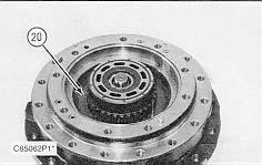
15. Remove disc (20) from the flange holder.
NOTICE
Do not let the components of barrel assembly (21) come apart during the removal from the travel motor body. All of the components in the barrel assembly must be reinstalled in their original locations.
16. Position the travel motor and the final drive as shown. Remove barrel assembly (21) from the travel motor body.
17. Shoe retainer (23) and piston shoe assemblies (22) are not serviced separately. Prior to the removal of the shoe retainer and piston shoe assemblies from barrel (24), put identification marks on piston shoe assemblies (22) as to their location in shoe retainer (23) and barrel (24). The piston shoe assemblies must be reinstalled in their original bores in the shoe retainer and the barrel.

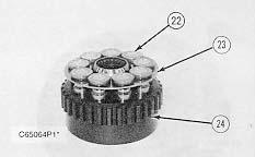
18. Remove shoe retainer (23) and piston shoe assemblies (22) from barrel (24). Separate the piston shoe assemblies from the shoe retainer.
19. Remove bushing (25) from the barrel. 20. Remove three pins (26) from the barrel.
There is a spring force against washer (28). When snap ring (27) is removed, the spring force will be released. To prevent possible personal injury, removal of the internal components in barrel (24) should be performed in a press in order to retain spring (29) and washer (28).
21. Put barrel (24) in a press. Install a suitable size drive plate that is slightly smaller in diameter than washer (28), on washer. Put a slight amount of compression on washer (28) with the press. Remove snap ring (27) and slowly release the spring compression. Remove washer (28), spring (29) and washer (30) from the barrel (24).

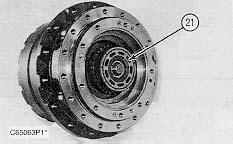
22. Remove swash plate (31) from the flange holder.
23. Remove shaft (32) from the flange holder.
24. Using a magnet, remove two steel balls (33) from the flange holder.
25. Remove two piston assemblies (34) and the two springs from the flange holder.
26. Fasten the final drive to Tooling (A) as shown. Remove sixteen bolts (35) and the washers that hold cover (36) in place.
27. Using a soft faced hammer, break the seal between cover (36) and ring gear (37). Remove the cover.
28. Remove thrust plate (38) from the carrier assembly.
29. Remove sun gear (39) from the carrier assembly.
30. Remove carrier assembly (40) by lifting it straight up.
31. Remove planetary gear (41) and bearing (42) from the carrier assembly.

32. Remove the other two planetary gears from the carrier assembly as in Step 31.
33. Remove four screws (43) and thrust plate (44) from the carrier assembly.
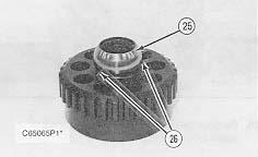
34. Remove sun gear (45) from the carrier assembly. Remove retaining ring (46) from sun gear (45).
35. Remove four planetary gears (46) from the carrier assembly.
36. Remove bearing (47) and bushing (48) from planetary gears (46). Remove thrust washers (49) from the carrier assembly.
38. Fasten Tooling (C) and a hoist to ring gear (37) as shown. Remove the ring gear from the main housing.
 37. Remove four socket head screws (50) and ring nut (51).
43.
NOTE: The following steps are for the assembly of the travel motor and the final drive.
44. Make sure all of the parts of the travel motor and the final drive are thoroughly clean and free of dirt and debris prior to assembly. Check the condition of all O-ring seals used in the travel motor and the final drive. If any of the seals are worn or damaged, use new parts for replacement. Reassemble the travel motor and the final drive on Tooling (A).
NOTICE
Refer to the topic "Assembly And Installation Of Conventional DuoCone Seals" in this module.
NOTE: The rubber seals and all of the surfaces that make contact with the seals must be clean and dry. After the installation of the seals, put clean SAE 30 weight oil on the contact surfaces of the metal seals.
 39. Remove bearing (52) from the ring gear.
40. If necessary, remove race (53) from the ring gear.
41. Remove Duo-Cone seal (54) and race (55) from the ring gear.
42. Remove bearing (56) from the main housing.
Remove Duo-Cone seal (57) from the main housing.
39. Remove bearing (52) from the ring gear.
40. If necessary, remove race (53) from the ring gear.
41. Remove Duo-Cone seal (54) and race (55) from the ring gear.
42. Remove bearing (56) from the main housing.
Remove Duo-Cone seal (57) from the main housing.
NOTICE
Do not scratch or damage the Duo-Cone seals in the main housing or the ring gear during assembly of these two components. After the installation of the ring gear on the main housing, there will be a small gap between the components. The gap is caused by the Duo-Cone seals and will be eliminated during installation of ring nut (51).

 45. Using Tool (D), install Duo-Cone seal (57) in the main housing.
46. Install bearing (56) on the main housing.
47. Install race (55) to the ring gear. Using Tool (D), install Duo-Cone seal (54) to the ring gear.
48. Reposition the ring gear and install race (53).
49. Install bearing (52) in the ring gear.
50. Fasten Tooling (C) and a hoist to ring gear (37) as shown. Install the ring gear on the main housing.
45. Using Tool (D), install Duo-Cone seal (57) in the main housing.
46. Install bearing (56) on the main housing.
47. Install race (55) to the ring gear. Using Tool (D), install Duo-Cone seal (54) to the ring gear.
48. Reposition the ring gear and install race (53).
49. Install bearing (52) in the ring gear.
50. Fasten Tooling (C) and a hoist to ring gear (37) as shown. Install the ring gear on the main housing.
51. Use the following procedure to make a preload adjustment of bearing (52) as follows:
a. Tighten nut (51) until there is no gap between the main housing and bearing (52).
b. Rotate ring gear (37) several turns.
c. Turn nut (51) in and/or out until rotational torque of ring gear (37) is 21 ± 5 N·m (15 ± 4 lb ft).

52. Install four screws (50). Tighten the screws to a torque of 40 ± 5 N·m (29 ± 4 lb ft).
53.
54. Install retaining ring (46) on sun gear (45).
55. Install thrust plate (44) and four screws (43). Tighten the screws to a torque of 44 ± 5 N·m (32 ± 4 lb ft).
56. Install bearing (42) and planetary gear (41) on the carrier shaft assembly.
57. Install the other two planetary gears on the carrier assembly as in Step 56.
58. Install planetary carrier (40) in the final drive housing.
 Put washer (49) on the carrier assembly shaft. Install bearing (47) and bushing (48) to planetary gear (46). Install gear (46) on the carrier assembly shaft.
Thank you very much for your reading. Please Click Here. Then Get COMPLETE MANUAL.NOWAITING

NOTE:
If there is no response to click on the link above, please download the PDF document first and then clickonit.
59. Install sun gear (39).
60. Install thrust plate (38) on the carrier assembly. Use an appropriate thrustr plate to get a clearance of 0.30 to 1.20 mm (.011 to .047 in) between the thrust plate and planetary carrier (40). Refer to the "Specifications module, 311B, 312B and 312 B L Excavators, Hydraulic Systems" for plate part numbers and thicknesses.
61. Make sure the machined surface of ring gear (37) and cover (36) is thoroughly clean, free of dirt and debris and is dry. Put a bead of 1U-8846 Gasket Maker around the machined surface of the ring gear. Put cover (36) in its original position on the ring gear.
62. Install bolts (35) and the washers that hold the cover. Tighten the sixteen bolts to a torque of 39 ± 2 N·m (22 ± 1 lb ft).
63. Position the travel motor and the final drive housing as shown. Install two balls (33) in the flange holder.
64. Install the two springs and two piston assemblies (34) in the flange holder. Put clean hydraulic oil on the components.


65. Put the bearing on shaft (32) and install the shaft in the travel motor housing.
66. Install swash plate (31). Make sure the swash plate is aligned with balls (33). Also, push on the swash plate from side to side to make sure it can move on the balls at the fixed position.
67. Install washer (30), spring (29) and washer (28) in barrel (24).
68. Use a press, and compress spring (29). Install retaining ring (27).


69. Install three pins (26) and bushing (25).
70. Install piston shoe assemblies (22) in their original bores in shoe retainer (23).
71. Put clean hydraulic oil in the bores of the barrel and on piston shoe assemblies (22). Install the piston shoe assemblies with the shoe retainer in their original bores in barrel (24).
NOTICE
During the installation of the barrel assembly (21), do not let the components fall apart.
72. Install barrel assembly (21) on the shaft as a unit. 73. Install disc (20) in the flange holder.74. Make sure brake piston (15) is thoroughly clean and free of dirt and debris. Check the condition of back-up rings (17) and (19) and O-ring seals (16) and (18). If the back-up rings or the O-ring seals are worn or damaged, use new parts for replacement.
75. Install back-up rings (17) and (19) and O-ring seals (16) and (18) on brake piston (15) as shown. Put a coat of 1U-6396 Assembly Compound on the back-up rings and the O-ring seals.
76. Put a thin coat of clean hydraulic oil on the surface of the travel motor body which makes contact with piston (15). Install piston (15) in the travel motor body by hand. It may be necessary to use a soft faced hammer to seat the piston properly.
77. Install valve plate (14) and eight springs (13) in the flange holder.
78. Install plunger (12) and spring (11) in the travel brake valve.
79. Put the O-ring seal on plug (10), and install the plug. Tighten the plug to a torque of 50 ± 3 N·m (37 ± 2 lb ft).

80. Install spool assembly (9), washer (8) and spring (7) in the travel brake valve.
81. Put the O-ring seals on caps (6). Install both caps (6) and cap mounting bolts (5). Tighten the cap mounting bolts to a torque of 59 ± 5 N·m (44 ± 4 lb ft).