
STEERING WHEEL FREEPLAY CHECK
With the vehicle stopped and tires pointed straight ahead, rock the steering wheel gently back and forth with light finger pressure.
Freeplay should not exceed the maximum. Freeplay mm(in.) Maximum 30(118) 30 (1.18)
IDLE–UP CHECK
1. TURN AIR CONDITIONING SWITCH OFF
2. CHECK IDLE–UP
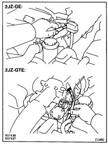
(a) Start engine and run it at idle. (b) Fully turn the steering wheel. (c) Check that the engine speed decreases when the air control valve hose is pinched.

(d) Check that the engine speed increases when the hose is released.
FLUID LEVEL CHECK
1. KEEP VEHICLE LEVEL
2. CHECK FLUID LEVEL

Check the fluid level in the reservoir. If necessary, add fluid.
Fluid: ATF DEXRON II
HINT: Check that the fluid level is within the HOT LEVEL range on the dipstick of the reservoir cap. If the fluid is cold, check that it is within the COLD LEVEL range.
3. BOOST FLUID TEMPERATURE
(a) Start the engine and run it at idle. (b) Turn the steering wheel from lock to lock several times to boost fluid temperature.
Fluid temperature: 80°C (176°F)
– STEERING ON–VEHICLE INSPECTION SR–7
4. CHECK FOR FOAMING OR EMULSIFICATION
If there is foaming or emulsification, bleed power steering system.
(See page SR–9 )
5.
CHECK FLUID LEVEL RISE
(a) With the engine idling, measure the fluid level in the reservoir. (b) Stop the engine.

(c) Wait a few minutes and remeasure the fluid level in the reservoir.
Fluid level rise mm (in.) Maximum 5(02) 5 (0.2)
If a problem is found, bleed power steering system. (See page SR–9 )
6. CHECK FLUID LEVEL
POWER STEERING FLUID REPLACEMENT
1. JACK UP FRONT OF VEHICLE AND SUPPORT IT WITH STANDS
2. DRAIN FLUID
(a) Disconnect the return hose from the PS vane pump. (b) Turn the steering wheel from lock to lock.
3. FILL OIL RESERVOIR
(a) Fill oil reservoir with fresh fluid.
Fluid: ATF DEXRON II
(b) Start engine.
(c) After 1 or 2 seconds, fluid will begin to discharge from the return hose.
(d) Stop the engine immediately.
NOTICE: Take care that some fluid remains in the oil reservoir.
(e) Repeat steps (a), (b), (c) and (d) until there is no more air in fluid.

(f) Connect the return hose.
4. BLEED POWER STEERING SYSTEM
(See page SR–9 )
SR–8 – STEERING ON–VEHICLE INSPECTION
POWER STEERING SYSTEM BLEEDING
1. JACK UP FRONT OF VEHICLE AND SUPPORT IT WITH STANDS
2. TURN STEERING WHEEL
With the engine stopped, turn the steering slowly from lock to lock several times.
NOTICE: Take care that some fluid remains in the oil reservoir.

3. LOWER VEHICLE
4. START ENGINE
Run the engine at idle for a few minutes.
5. TURN STEERING WHEEL
(a) With the engine at idling, turn the wheel to left or right full lock and keep it there for 2–3 seconds, then turn the wheel to the opposite full lock and keep it there for 2–3 seconds.
(b) Repeat (a) several times.
6. STOP ENGINE
7. CHECK FOR FOAMING OR EMULSIFICATION
If the system has to be bled twice specifically because of foaming or emulsification, check for fluid leaks in the system.
8. CHECK FLUID LEVEL (See page SR–7 )
– STEERING ON–VEHICLE INSPECTION SR–9
FLUID PRESSURE CHECK
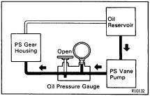
1. CONNECT OIL PRESSURE GAUGE
(a) Disconnect the pressure feed tube from the PS vane pump. (See page SR–26 ) (b) Connect the gauge over a new gasket, as shown below.
NOTICE: Check that the valve of the gauge is in the open position.
2. BLEED POWER STEERING SYSTEM (See page SR–9 )

3. BOOST FLUID TEMPERATURE
(a) Start the engine and run it at idle. (b) Turn the steering wheel from lock to lock several times to boost fluid temperature. Fluid temperature: 80°C (176°F)
4.
CHECK FLUID PRESSURE READING WITH VALVE CLOSED

With the engine idling, close the oil pressure gauge valve and observe the reading on the gauge.
Fluid pressure kPa (kgf/cm2, psi)
Minimum 7355(751067) 7,355 (75, 1,067)
NOTICE:
• Do not keep the valve closed for more than 10 seconds.
• Do not let the fluid temperature become too high.
SR–10 – STEERING ON–VEHICLE INSPECTION
5. CHECK FLUID PRESSURE READING WITH VALVE OPENED
(a) With the engine idling, open the valve fully.
(b) Measure the fluid pressure at engine speeds of 1,000 rpm and 3,000 rpm.
Fluid pressure kPa (kgf/cm2, psi)
Difference 490 (5, 71) or less
NOTICE: Do not turn the steering wheel.
6. CHECK FLUID PRESSURE READING WITH STEERING WHEEL TURNED TO FULL LOCK
With the engine idling and valve fully opened, turn the wheel to full lock.
Fluid pressure kPa (kgf/cm2, psi)
Minimum 7,355 (75, 1,067)
NOTICE:
• Do not maintain lock position for more than 10 seconds.
• Do not let the fluid temperature become too high.
7. DISCONNECT OIL PRESSURE GAUGE
(a) Disconnect the pressure gauge. (b) Connect the pressure feed tube. (See page SR–32 )


8. BLEED POWER STEERING SYSTEM (See page SR–9 )
STEERING EFFORT MEASUREMENT
1. CENTER STEERING WHEEL
2.
MEASURE STEERING EFFORT
(a) Remove the steering wheel pad. (See page SR–14 )
(b) Start the engine and run it at idle.
(c) Measure the steering effort in both directions. Maximum steering effort: 6.9 N m (70 kgf cm, 61 in. lbf)
If steering effort is excessive, repair the power steering unit. HINT: Be sure to consider the tire type, pressure and contact surface before making your diagnosis.
(d) Tighten the steering wheel set nut. Torque: 35 N⋅ m (360 kgf⋅ cm, 26 ft⋅ lbf)
(e) Install the steering wheel pad.
(See page SR–22 )
– STEERING ON–VEHICLE INSPECTION SR–11
TILT STEERING COLUMN COMPONENTS

SR–12 – STEERING TILT STEERING COLUMN
COMPONENTS

– STEERING TILT STEERING COLUMN SR–13
STEERING COLUMN REMOVAL
1. REMOVE STEERING WHEEL PAD
(a) Place the front wheels facing straight ahead. (b) Remove the No.2 and No.3 covers. (c) Using a torx socket wrench, loosen the 3 torx screws.
HINT: Loosen the 3 screws until the groove along the screw circumference catches on the screw case.
(d) Pull the pad out from the steering wheel and disconnect the airbag connector.


NOTICE: When removing the pad, take care not to pull the airbag wire harness.
CAUTION:
• When storing the pad, keep the upper surface of the pad facing upward.
• Never disassemble the pad.
2. REMOVE STEERING WHEEL
(a) Disconnect the connector. (b) Remove the wheel set nut. (c) Place matchmarks on the wheel and main shaft. (d) Using SST, remove the wheel. SST 09950–50010 (09951–05010, 09952–05010, 09953–05020, 09954–05020)

3. REMOVE UPPER AND LOWER COLUMN COVERS
Remove 5 screws.
4. REMOVE THESE PARTS: (See page BO–45 )
(a) Console panel upper (b) Cluster finish panel (c) Cluster finish panel RH (d) Cluster finish panel LH (e) Cluster finish panel center (f) Finish panel lower (g) Finish panel lower LH (h) Register No.2 duct
SR–14 – STEERING TILT STEERING COLUMN
5. REMOVE COMBINATION SWITCH
(a) Remove the 4 screws. (b) Disconnect the 4 connectors and airbag connector.
6. DISCONNECT INTERMEDIATE SHAFT
(a) Place matchmarks on the intermediate shaft and control valve shaft. (b) Loosen the bolt B and remove the bolt A.

7. REMOVE STEERING COLUMN ASSEMBLY

(a) Remove the brake pedal return spring. (b) Loosen the hole cover clamp. (c) Remove the 4 nuts.
STEERING COLUMN DISASSEMBLY

NOTICE: When using a vise, do not overtighten it.
1. REMOVE IGNITION KEY CYLINDER ILLUMINATION 2. REMOVE INTERMEDIATE SHAFT Remove the bolt.
3. REMOVE SLIDING YOKE AND SHAFT THRUST STOPPER
(a) Remove the bolt. (b) Shift the stopper. (c) Place matchmarks on the yoke and main shaft.
4. REMOVE COLUMN LOWER COVER Loosen the clamp.
5. REMOVE COLUMN UPPER BRACKET
(a) Using a centering punch, mark the center of the 2 tapered–head bolts. (b) Using a 4–5 mm (0. 16–0.20 in.) dr ill, drill into the 2 tapered–head bolts. (c) Using a screw extractor, remove the 2 tapered–head bolts. (d) Remove the bracket and column upper clamp.
6. REMOVE WIRING HARNESS CLAMP AND COLUMN PROTECTOR
7. REMOVE COMPRESSION SPRING
(a) Using a torx socket wrench, remove the screw. (b) Remove the 2 bushings from the spring.
8. REMOVE 3 TENSION SPRINGS
9. REMOVE TURN SIGNAL BRACKET Remove the 2 bolts.
– STEERING TILT STEERING COLUMN SR–15
Thank you very much foryourreading. PleaseClickHere Then Get More Information.