
Shutdown SIS
Previous Screen
Product: MOBILE HYD POWER UNIT
Model: 385C L MOBILE HYD POWER UNIT M3W
Configuration: 385C L Mobile Hydraulic Power Unit M3W00001-UP (MACHINE) POWERED BY C18 Engine
Disassembly and Assembly
385C Excavator and 385C MHPU Mobile Hydraulic Power Unit Machine Systems
Final Drive - Disassemble
SMCS - 4050-015
Disassembly Procedure
Table 1
Required Tools
Start By:
A. Remove the final drive. Refer to Disassembly and Assembly, "Final Drive - Remove".
Note: Cleanliness is an important factor. Before you begin the disassembly procedure, the exterior of the components should be thoroughly cleaned. This will help to prevent dirt from entering the internal mechanism. Precision components can be damaged by contaminants or by dirt. Perform disassembly procedures on a clean work surface. Keep components covered and protected at all times.
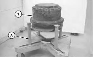
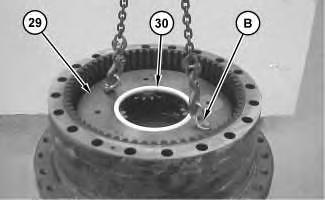
1. Fasten final drive (1) to Tooling (A). Put an alignment mark across the sections of final drive (1) for assembly purposes. All parts must be reinstalled in the original locations. The weight of final drive (1) is approximately 1020 kg (2250 lb).
2. Remove socket setscrews (2) from housing cover (3) .
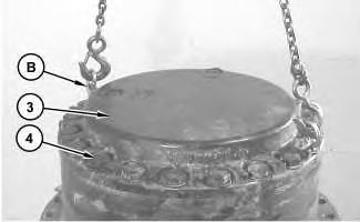
 Illustration 1
g01284546
Illustration 2
g01284563
Illustration 3
g01284577
Illustration 1
g01284546
Illustration 2
g01284563
Illustration 3
g01284577
3. Fasten Tooling (B) and a suitable lifting device to housing cover (3) .

4. Remove bolts (4) and the washers. Use a soft faced hammer in order to break the seal between housing cover (3) and the ring gear. Remove housing cover (3). The weight of housing cover (3) is approximately 95 kg (210 lb).
5. Remove spacer (5) and the shims from housing cover (3) .
6. Remove socket head bolts (6) and ring gear (7) from housing cover (3) .
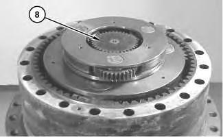
7. Remove sun gear (8) .
Illustration 4 g01284579 Illustration 5 g012845898. Use Tooling (B) and a suitable lifting device in order to remove carrier assembly (9). The weight of carrier assembly (9) is approximately 43 kg (95 lb).
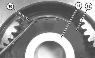
9. Remove retaining ring (10), spacer (11), and sun gear (12) .
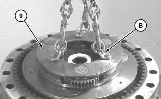 Illustration 6 g01284593
Illustration 7
g01284596
Illustration 8
g01284599
Illustration 6 g01284593
Illustration 7
g01284596
Illustration 8
g01284599
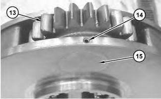
10. Drive spring pin (14) into planetary shaft (15). Remove planetary shaft (15) and planetary gear assembly (13) .
Illustration 9
g01284603
11. Remove washers (16) and bearing (17) from planetary gear (18). Remove spring pin (14) from planetary shaft (15) .
12. Repeat Steps 10 and 11 for the remaining planetary gear assemblies.
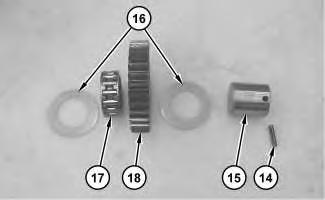
Illustration 10
g01284605
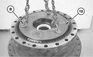
13. Use Tooling (B) and a suitable lifting device in order to remove carrier assembly (19). The weight of carrier assembly (19) is approximately 95 kg (210 lb).
14. Remove retaining ring (20), spacer (21), and sun gear assembly (22) .
Illustration 12
15. Drive spring pin (23) into planetary shaft (25). Remove planetary shaft (25) and planetary gear assembly (24) .
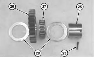
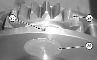
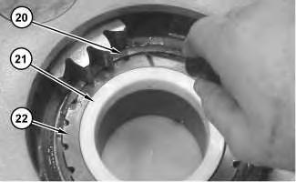 Illustration 11
g01284609
g01284612
Illustration 13
g01284616
Illustration 11
g01284609
g01284612
Illustration 13
g01284616
16. Remove washers (28) and bearing (27) from planetary gear (26). Remove spring pin (23) from planetary shaft (25) .
17. Repeat Steps 15 and 16 for the remaining planetary gear assemblies.
Illustration 14 g01284622
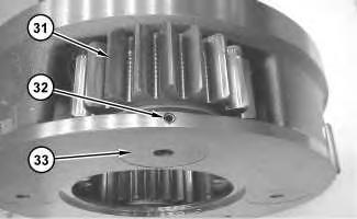
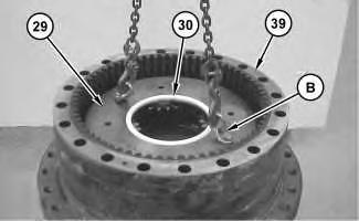
18. Remove spacer (30). Use Tooling (B) and a suitable lifting device in order to remove carrier assembly (29). The weight of carrier assembly (29) is approximately 132 kg (290 lb).
Illustration 15 g01284632
19. Drive spring pin (32) into planetary shaft (33). Remove planetary shaft (33) and planetary gear assembly (31) .
Illustration 16
g01284637
20. Remove washers (34) and (38), and bearings (35) and (37) from planetary gear (36). Remove spring pin (32) from planetary shaft (33) .
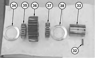
21. Repeat Steps 19 and 20 for the remaining planetary gear assemblies.
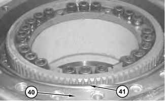
Illustration 17
g01284647
22. Use Tooling (B) and a suitable lifting device in order to remove ring gear (39) from housing (40). The weight of ring gear (39) is approximately 155 kg (340 lb).
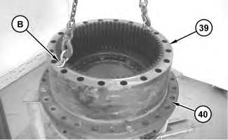
Illustration 18 g01284657
23. Remove O-ring seal (41) from housing (40) .
Illustration 19 g01284704
24. Place suitable cribbing under motor housing (42) in order to support motor housing (42) .

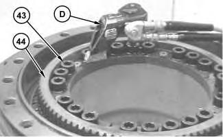
Illustration 20 g01284709

Illustration 21 g00865969
25. Use Tooling (D) in order to remove bolts (43) from coupling gear (44) .

Note: A part of Tooling (D) must be modified. Cut Length (X) on the Hex Bit Socket to a length of 14.0 mm (0.55 inch).
Illustration 22 g01284713
26. Install Tooling (E) in coupling gear (44), as shown. Tighten Tooling (E) evenly in order to loosen coupling gear (44). Remove coupling gear (44) from motor housing (42) .
Illustration 23 g01284718
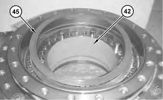
27. Remove shims (45) from motor housing (42) .
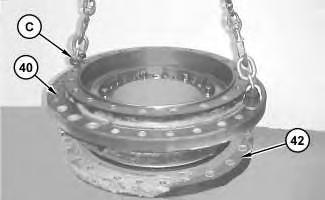
28. Remove bolts (46). Use Tooling (C) and a suitable lifting device in order to separate housing (40) from motor housing (42). Motor housing (42) will rest on the suitable cribbing. The weight of housing (40) is approximately 250 kg (550 lb).
29. Remove bearing cone (47) from housing (40) .
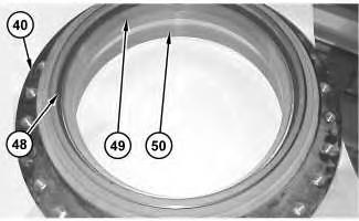

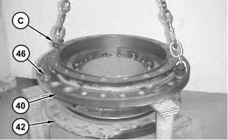 Illustration 24
g01284723
Illustration 25
g01284734
Illustration 26
g01284738
Illustration 24
g01284723
Illustration 25
g01284734
Illustration 26
g01284738
30. Use Tooling (C) and a suitable lifting device in order to flip housing (40) on the other side. The weight of housing (40) is approximately 250 kg (550 lb).
31. Remove Duo-Cone seal (48), and bearing cups (49) and (50) from housing (40) .
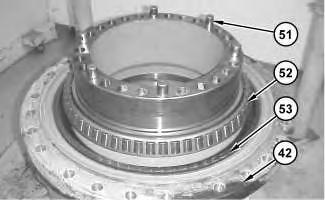
32. Remove pins (51) from motor housing (42), if necessary.
33. Remove bearing cone (52) from motor housing (42) .
34. Remove Duo-Cone seal (53) from motor housing (42) .
Illustration 27 g01284743Shutdown SIS
Previous Screen
Product: MOBILE HYD POWER UNIT
Model: 385C L MOBILE HYD POWER UNIT M3W
Configuration: 385C L Mobile Hydraulic Power Unit M3W00001-UP (MACHINE) POWERED BY C18 Engine
Disassembly and Assembly
385C Excavator and 385C MHPU Mobile Hydraulic Power Unit Machine Systems
Final Drive - Assemble
SMCS - 4050-016
Assembly
Procedure
Table 1
Required Tools
Note: Cleanliness is an important factor. Before assembly, thoroughly clean all parts in cleaning fluid. Allow the parts to air dry. Do not use wiping cloths or rags to dry parts. Lint may be deposited on the parts which may cause trouble. Inspect all parts. If any parts are worn or damaged, use new parts for replacement. Dirt and other contaminants can damage the precision component. Perform assembly procedures on a clean work surface. Keep components covered and protected at all times.
Note: Check the condition of all the O-ring seals that are used in the final drive. If any of the seals are worn or damaged, use new parts for replacement.
1. Reassemble the final drive on Tooling (A) and suitable cribbing.
Note: Refer to Disassembly and Assembly, "Duo-Cone Conventional Seals - Install".
Note: The rubber portion of Duo-Cone seal (53) and all surfaces that contact Duo-Cone seal (53) must be clean and dry. After installation of Duo-Cone seal (53) , apply Tooling (L) on the contact surfaces of the metal portion of Duo-Cone seal (53) .
2. Use Tooling (F) in order to install Duo-Cone seal (53) .
3. Apply Tooling (H) to the surfaces on motor housing (42) that will contact bearing cone (52) .
4. Raise the temperature of bearing cone (52) . Use a suitable press in order to install bearing cone (52) in motor housing (42) .
5. Apply Tooling (H) to the surfaces that contact pins (51) . Install pins (51) .
6. Apply Tooling (H) to the surfaces that contact bearing cups (49) and (50) on housing (40) . Install bearing cups (49) and (50) in housing (40) .
Note: Refer to Disassembly and Assembly, "Duo-Cone Conventional Seals - Install".
Note: The rubber portion of Duo-Cone seal (53) and all surfaces that contact Duo-Cone seal (48) must be clean and dry. After installation of Duo-Cone seal (48) , apply Tooling (L) on the contact surfaces of the metal portion of Duo-Cone seal (48) .
Note: Make sure that the Duo-Cone seals (53) and (48) are not scratched or damaged during the assembly of housing (40) or during the assembly of motor housing (42) . After installation of housing (40) on the motor housing (42) , there will be a small gap between the components. The gap is caused by the Duo-Cone seals. The gap will be eliminated during installation of the gear.
7. Use Tooling (F) in order to install Duo-Cone seal (48) .
Illustration 2 g01284738 Illustration 3 g012855188. Attach Tooling (C) and a suitable lifting device to housing (40) in order to flip housing (40) on the other side.

9. Use Tooling (C) and a suitable lifting device in order to install housing (40) on motor housing (42) . The weight of the housing (40) is approximately 250 kg (550 lb).
10. Install bearing cone (47) .
11. Use the following procedure to determine the bearing preload and the correct number of shims.
a. Use a depth micrometer in order to measure the step length of coupling gear (44) . Take measurements at several different locations around gear (44) . Compute the average of the measured dimensions and record the number. Call this Dimension (X) .
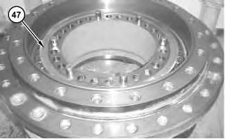 Illustration 4
g01285527
Illustration 5
g01285536
Illustration 4
g01285527
Illustration 5
g01285536
b. Use Tooling (G) in order to apply a load of 10700 kPa (1550 psi) to bearing cone (47) (not shown) and to bearing cone (52) (not shown). The load will seat bearing cone (47) (not shown) and bearing cone (52) (not shown). A pressure of 10700 kPa (1550 psi) on the electric hydraulic pump of Tooling (G) will result in a pressure of 10000 kg (22050 lb) on bearing cone (47) (not shown) and on bearing cone (52) (not shown). Rotate the housing in order to seat bearing cone (47) (not shown) and bearing cone (52) (not shown). Reduce the load on the electric hydraulic pump of Tooling (G) to 4825 kPa (700 psi).
c. Rotate Tooling (G) by 90° and repeat Step 11.b.
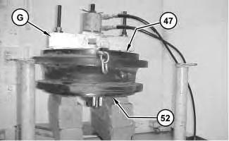
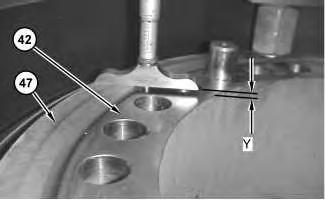
d. Maintain the load on bearing cone (47) (not shown) and on bearing cone (52) (not shown). Use a depth micrometer and measure the distance between the top face of housing (42) and bearing cone (47) . Take this measurement in several locations around bearing cone (47) . Compute the average of the measured dimensions and record the number. Call this Dimension (Y) .
e. Determine the correct thickness of the shim pack that will be installed between bearing cone (47) and coupling gear (44) . The shim pack thickness is equal to Dimension (Y) minus Dimension (X) . Tolerance for the shim pack is 0.10 mm (0.003 inch).
Illustration 6 g01285550 Illustration 7 g01285553Note: If two shims are required, install the thinner shim next to coupling gear (44) when coupling gear (44) is installed.
12. Place shims (45) in the correct position on motor housing (42) . If two shims were required, put the thinner shim in contact with coupling gear (44) . Make sure that all of the holes in the components are in alignment with each other. Put coupling gear (44) in the original position on the motor housing.
13. ApplyTooling (J) on the threads of bolts (43) . Install bolts (43) in order to secure coupling gear (44) in place. Tighten bolts (43) evenly and tighten bolts (43) in diagonally opposite pairs. Tighten bolts (43) to a torque of 900 ± 100 N·m (665 ± 75 lb ft).
Illustration 8
g01284718
Illustration 9
g01284709
14. Install O-ring seal (41) in main housing (40) .

15. Use Tooling (C) and a suitable lifting device in order to position housing (40) and motor housing (42) on Tooling (A) . Remove the suitable cribbing. The weight of both housings is approximately 430 kg (950 lb).
Illustration 10
g01284657
Illustration 11
g01285592
Illustration 12
g01284647
16. Thoroughly clean the mating surface of housing (40) that contacts ring gear (39) . Apply a bead of Tooling (K) on the mating surface of ring gear (39) . Use Tooling (B) and a suitable lifting device in order to position ring gear (39) on housing (40) . Make sure that the alignment mark on housing (40) and ring gear (39) line up with each other. It may be necessary to use a soft faced hammer to seat ring gear (39) on housing (40) .
17. Assemble planetary gear assembly (31) , as follows:
13
Illustration 14
a. Apply clean SAE 30 oil on bearings (35) and (37) . Install bearings (35) and (37) in planetary gear (36) .
b. Install washers (34) and (38) on each side of planetary gear (36) .
c. Install planetary gear assembly (31) and washers (34) and (38) in carrier assembly (29) .
d. Install planetary shaft (33) in carrier assembly (29) and through planetary gear assembly (31) . Make sure that the spring pin hole in planetary shaft (33) is in alignment with the spring pin hole in the carrier.
Illustration g01284637 g01284632Illustration 15
g03142259
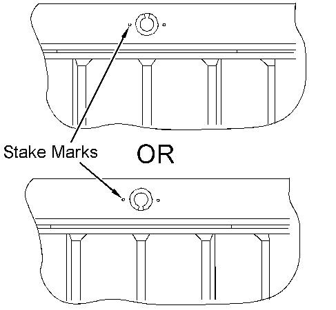
e. Install spring pin (32) in the carrier and into planetary shaft (32) . Make sure that the spring pin hole in planetary shaft (32) is in alignment with the spring pin hole in the carrier.
f. Orient the split in spring pin (32) as shown. Make a stake mark on each side of the spring pin hole in the carrier. This will prevent spring pin (32) from falling out of the spring pin hole. Each stake mark should be approximately to 2.25 ± 0.75 mm (0.089 ± 0.030 inch) from the outside diameter of the spring pin hole.
g. Repeat Steps 17.a through 17.f in order to install the other three planetary gear assemblies in carrier assembly (29) .
g01285680
18. Fasten Tooling (B) and a suitable lifting device to carrier assembly (29) . Put carrier assembly (29) in position in ring gear (39) . It may be necessary to move carrier assembly (29) back and forth during installation in order to ensure that all gears engage properly.
19. Install spacer (30) .
20. Assemble planetary gear assembly (24) , as follows:
g01284616
a. Apply clean SAE 30 oil on bearing (27) . Install bearing (27) in planetary gear (26) .
b. Install washers (28) on each side of planetary gear assembly (24) .
c. Install washers (28) and planetary gear assembly (24) in carrier assembly (19) .
Illustration 16 Illustration 17g01284612
d. Install planetary shaft (25) in carrier assembly (19) and through planetary gear assembly (24) . Make sure that the spring pin hole in planetary shaft (25) is in alignment with the spring pin hole in the carrier.
g03142259
e. Orient the split in spring pin (23) as shown. Make a stake mark on each side of the spring pin hole in the carrier. This will prevent spring pin (23) from falling out of the spring pin hole. Each stake mark should be approximately to 2.25 ± 0.75 mm (0.089 ± 0.030 inch) from the outside diameter of the spring pin hole.
Illustration 18
Illustration 19
Suggest:
If the above button click is invalid.
Please download this document first, and then click the above link to download the complete manual.
Thank you so much for reading

f. Repeat Steps 20.a through 20.e in order to install the other two planetary gear assemblies in carrier assembly (19) .
Illustration 20
21. Install sun gear assembly (22) , spacer (21) , and retaining ring (20) .
Illustration 21
22. Use Tooling (B) and a suitable lifting device in order to install carrier assembly (19) . The weight of carrier assembly (19) is approximately 95 kg (210 lb).
g01284609
g01284605