the portfolio of


the portfolio of
Fall 2023
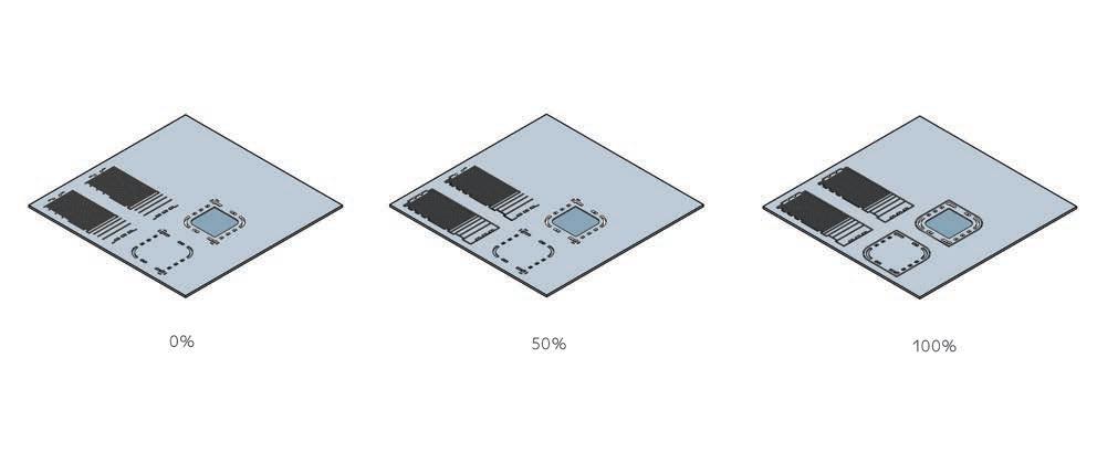
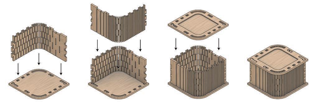
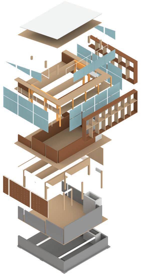
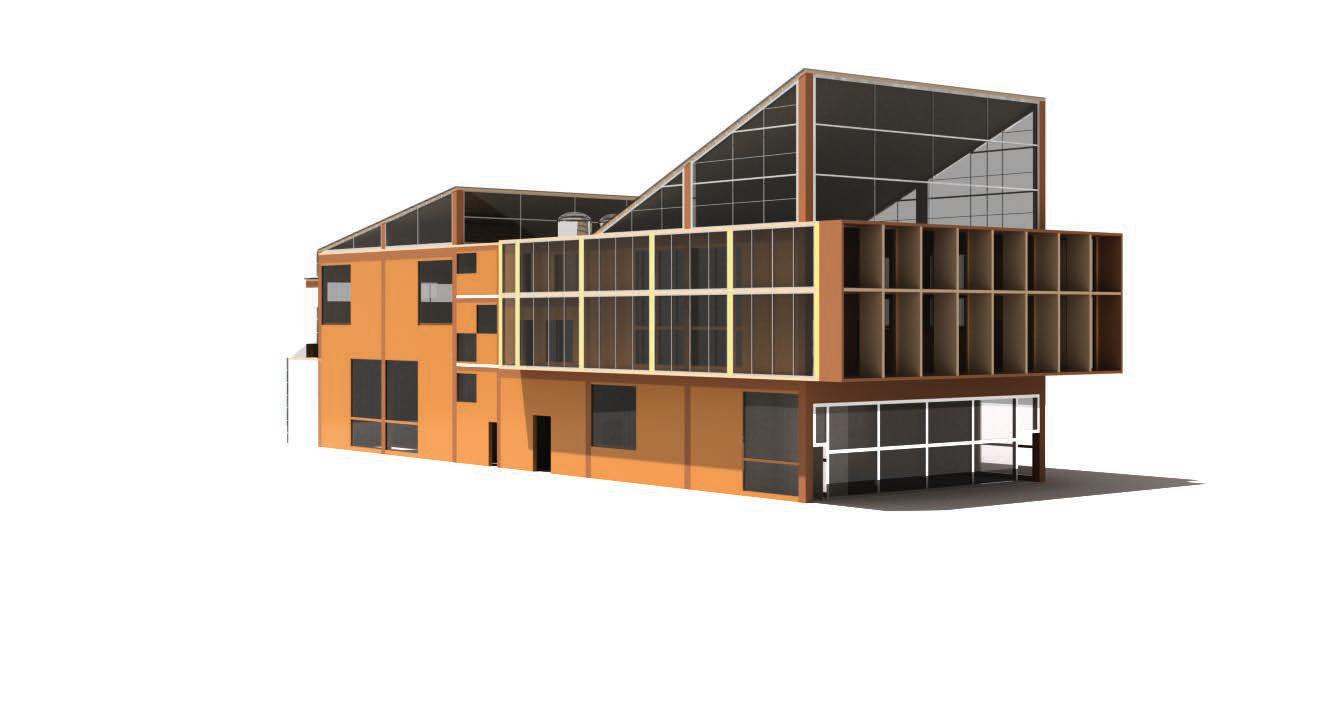
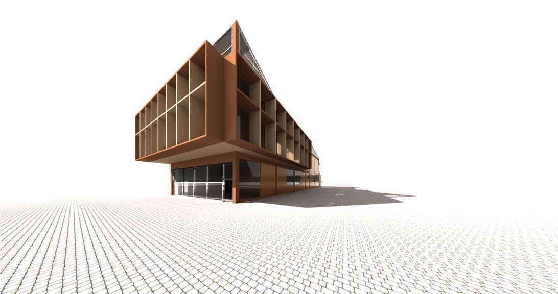
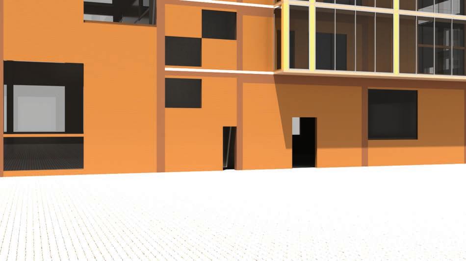
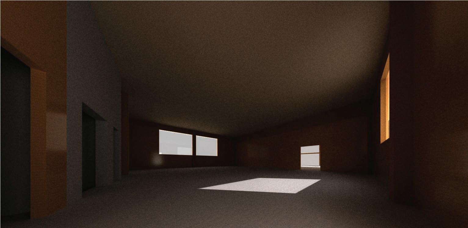
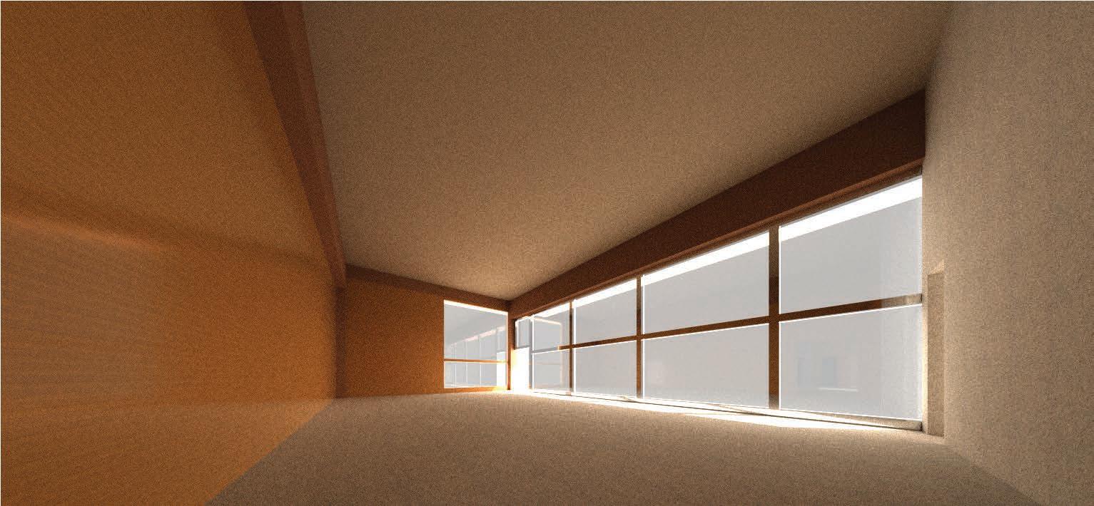
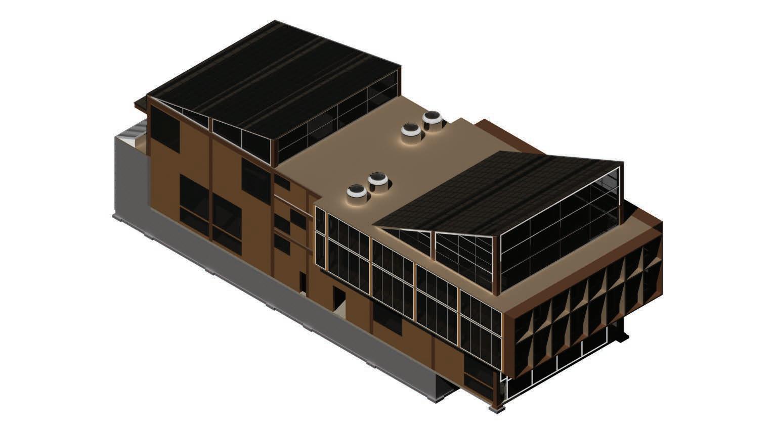
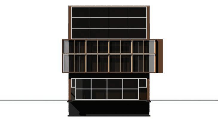
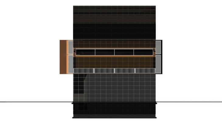
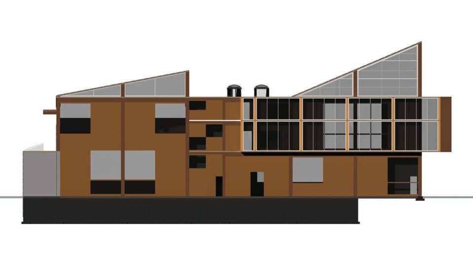
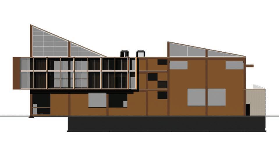
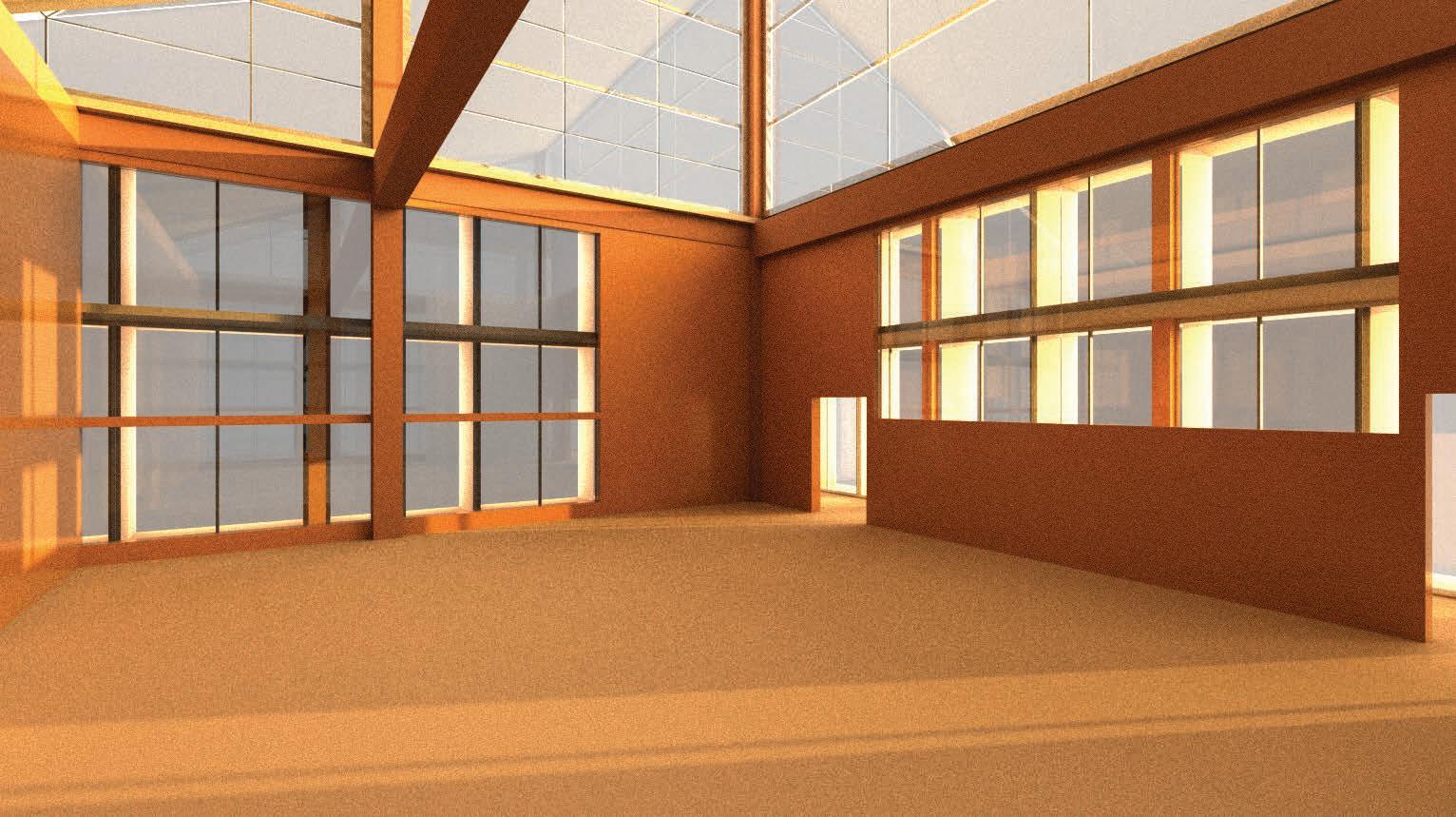
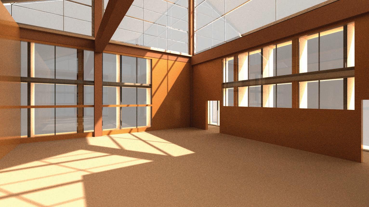
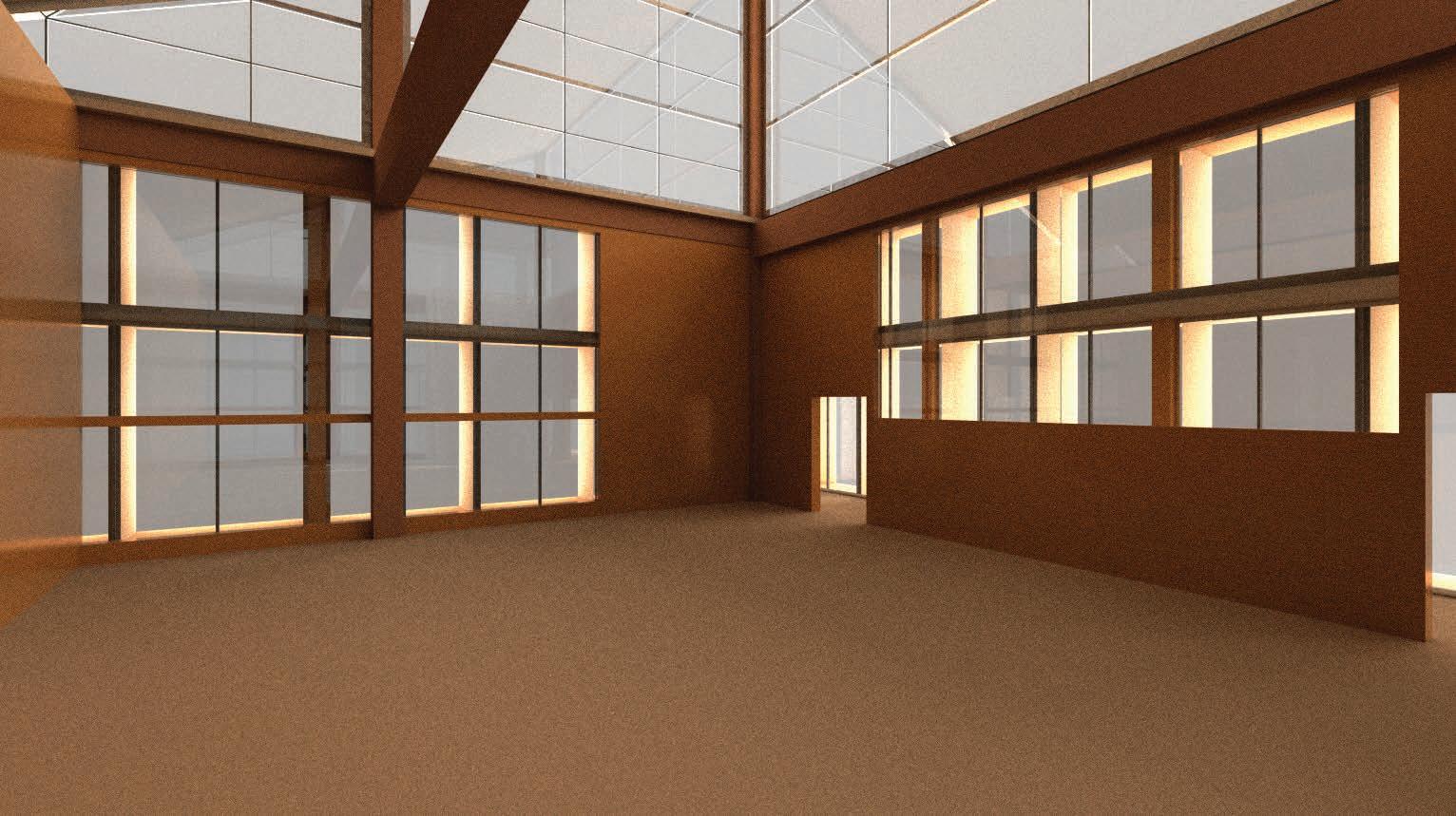
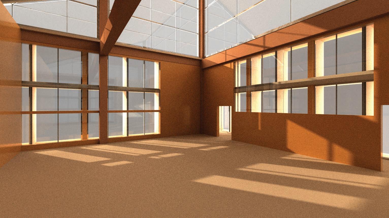
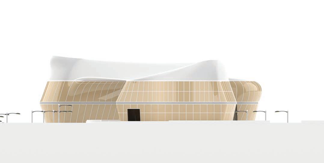
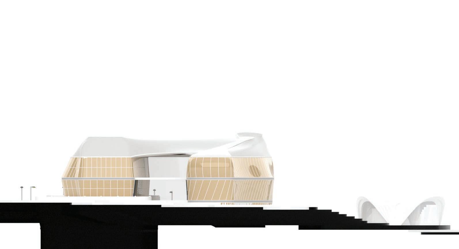
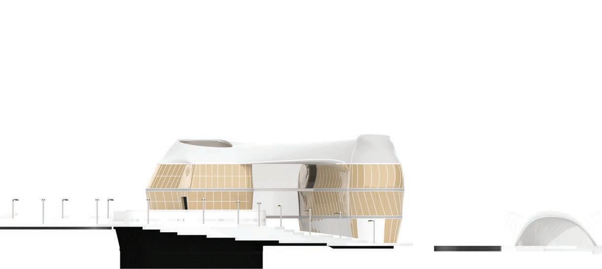
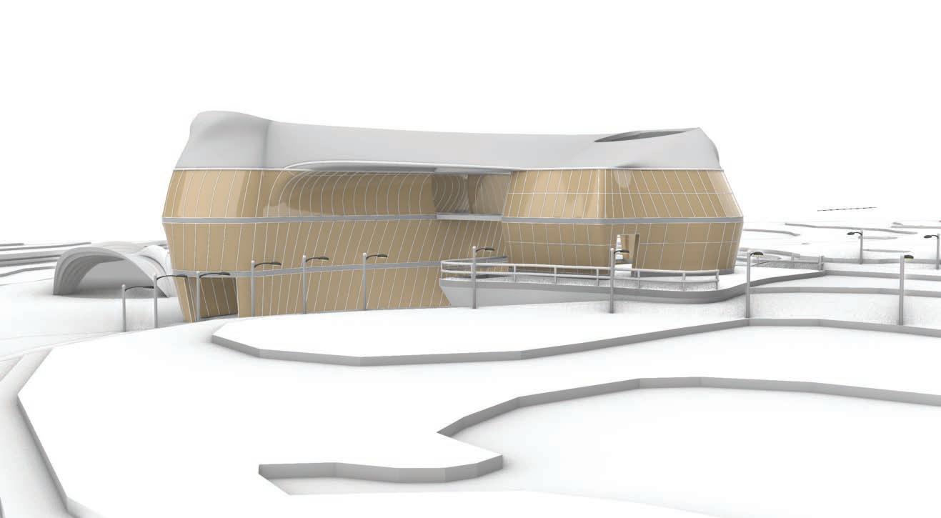
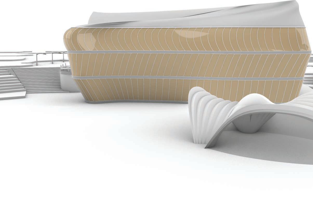
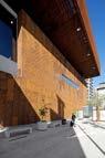
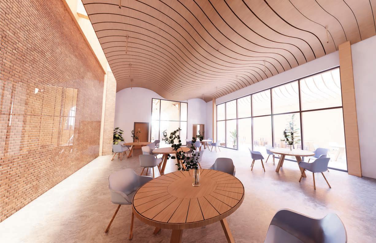
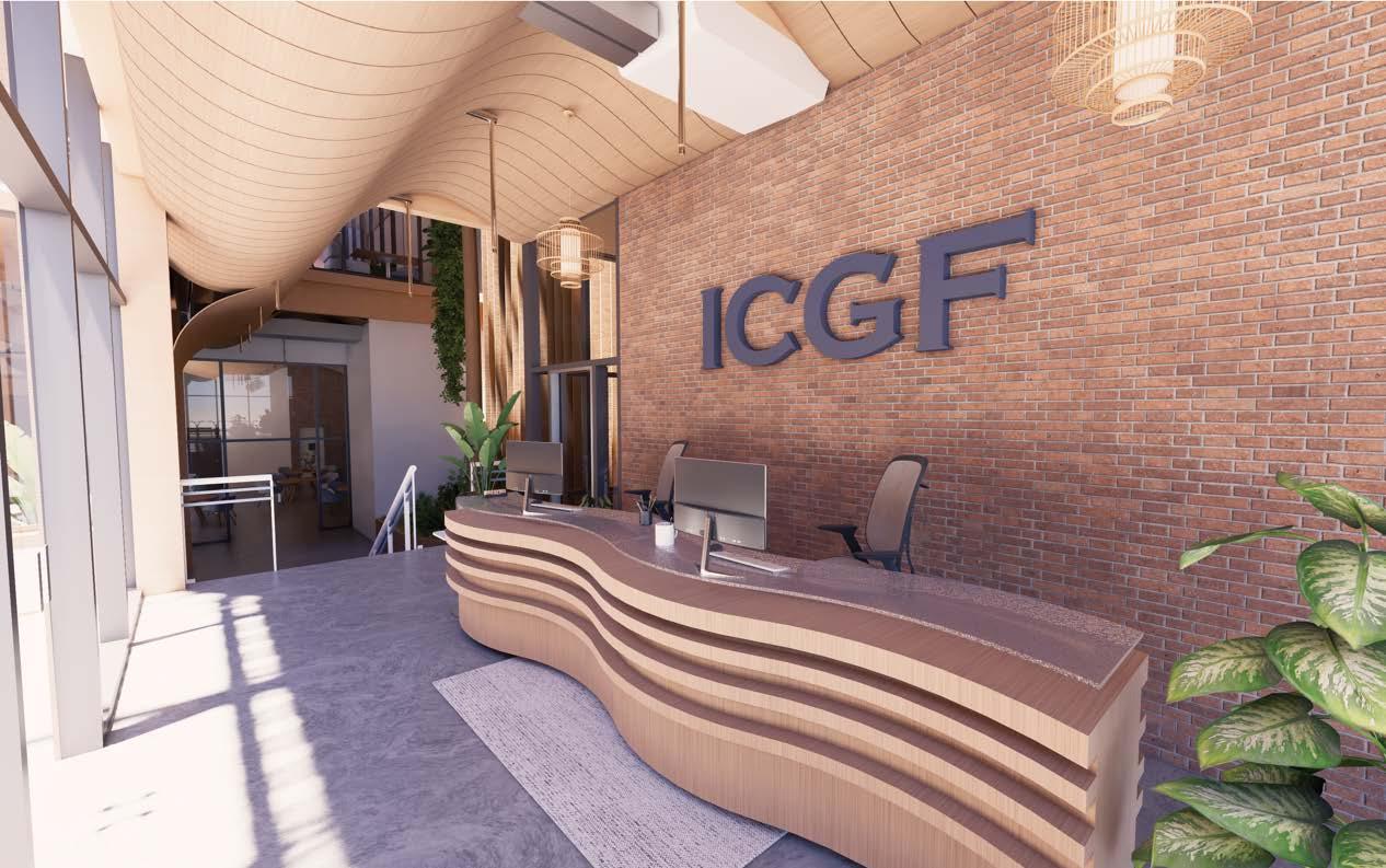
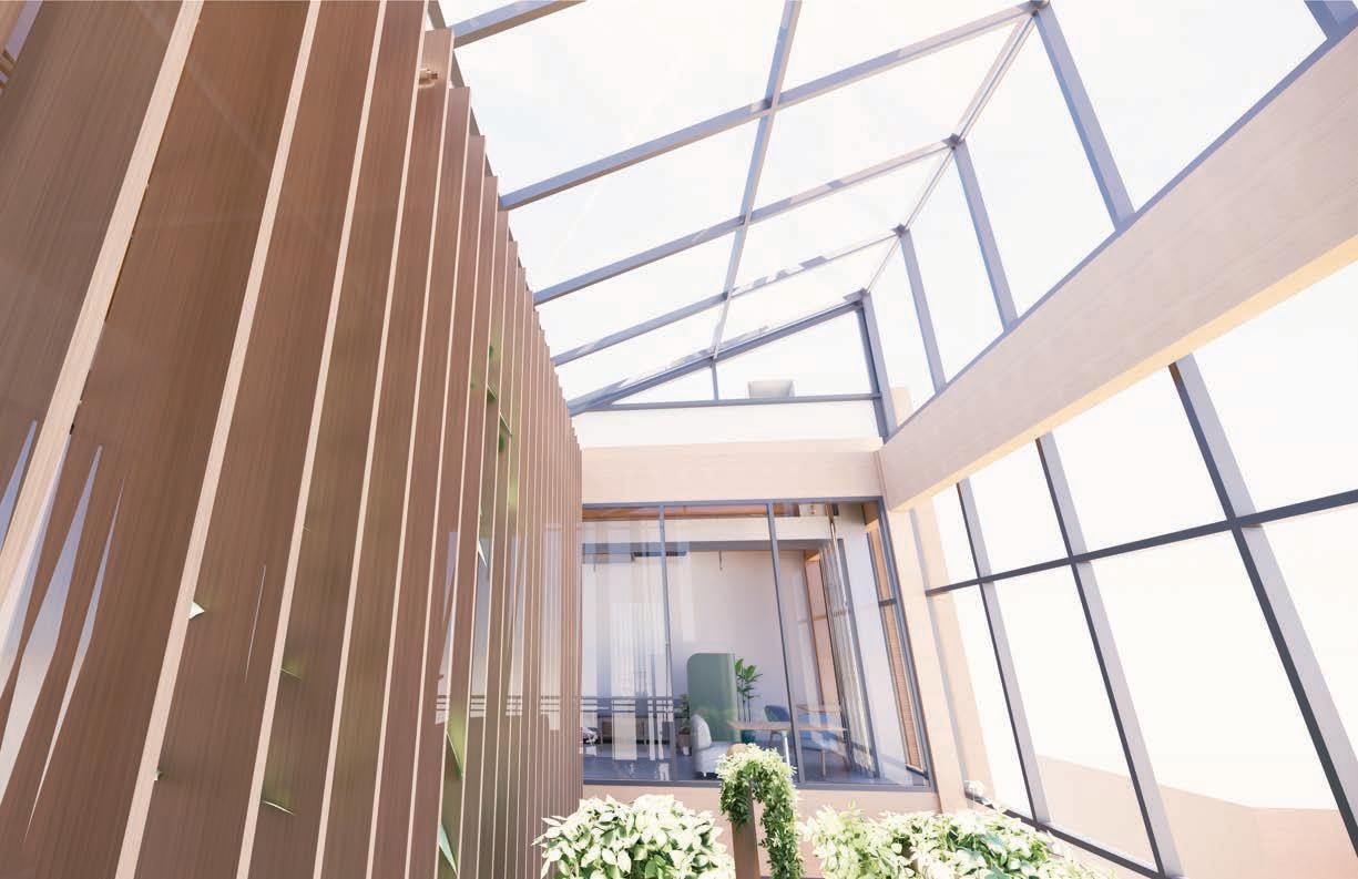
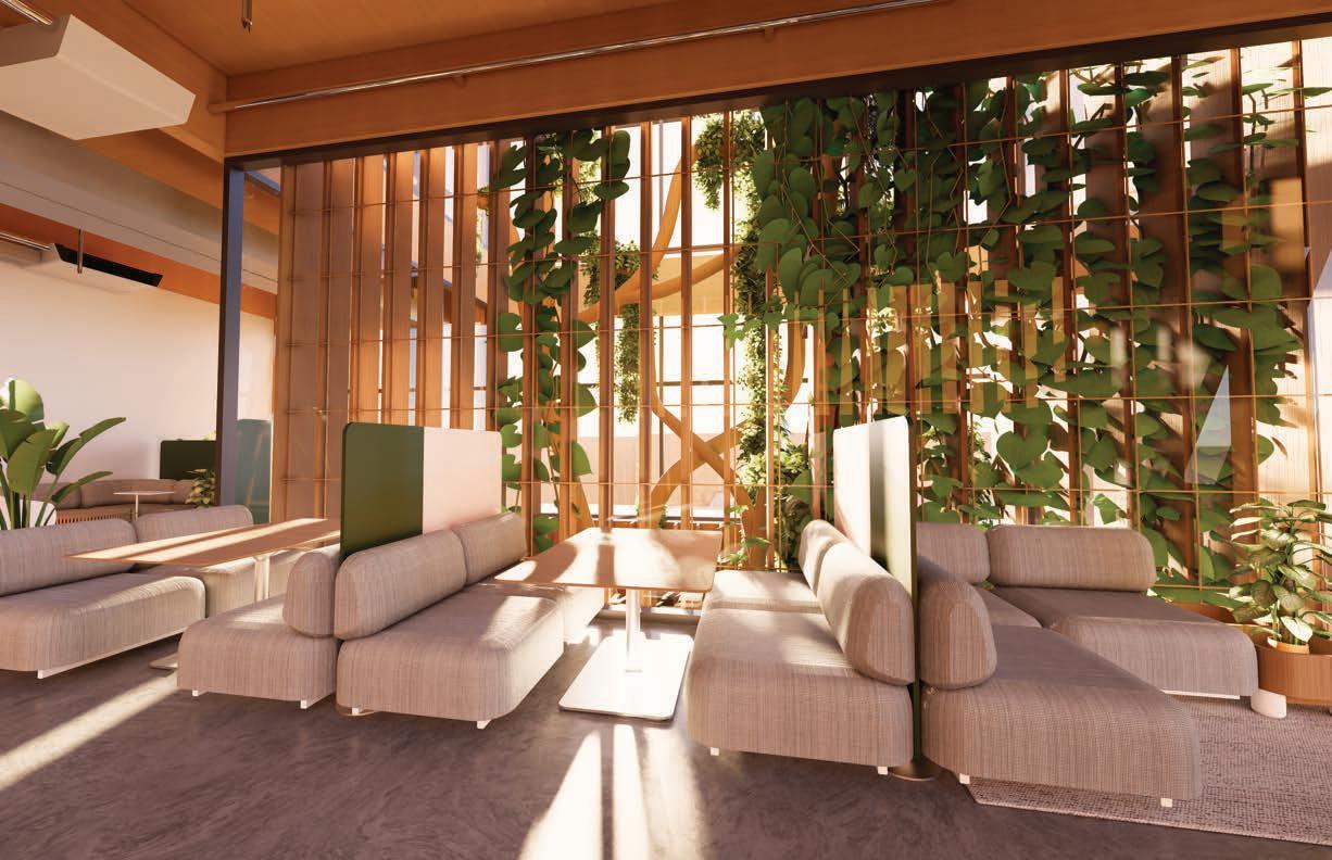
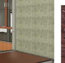
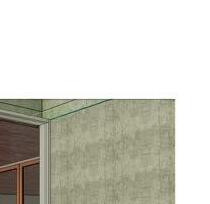
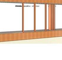
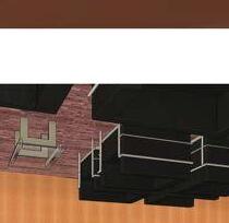
The building is designed to maximize square footage while optimizing solar energy use and ensuring proper circulation. Its layout prioritizes efficient space use, with a focus on natural light and airflow. Prefabricated wood panels and modularity are incorporated for flexibility and sustainability, allowing for easy adaptation of the space over time. The design enhances both energy efficiency and circulation, creating a functional, well-ventilated environment.
DESIGN INTEGRATION Fall 2023

DESIGN INTEGRATION Fall 2023
DESIGN INTEGRATION Fall 2023
DESIGN INTEGRATION Fall 2023
DESIGN INTEGRATION Fall 2023
DESIGN INTEGRATION Fall 2023
DESIGN INTEGRATION Fall 2023
DESIGN INTEGRATION Fall 2023
DESIGN INTEGRATION Fall 2023
DESIGN INTEGRATION Fall 2023
DESIGN INTEGRATION Fall 2023
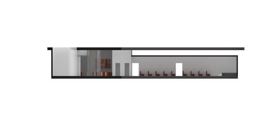
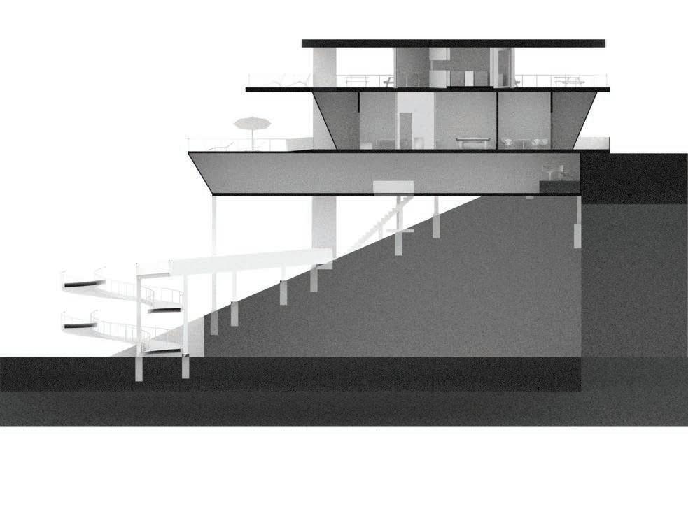
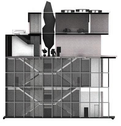
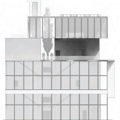
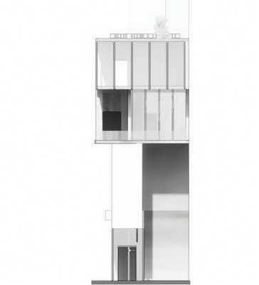
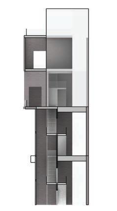
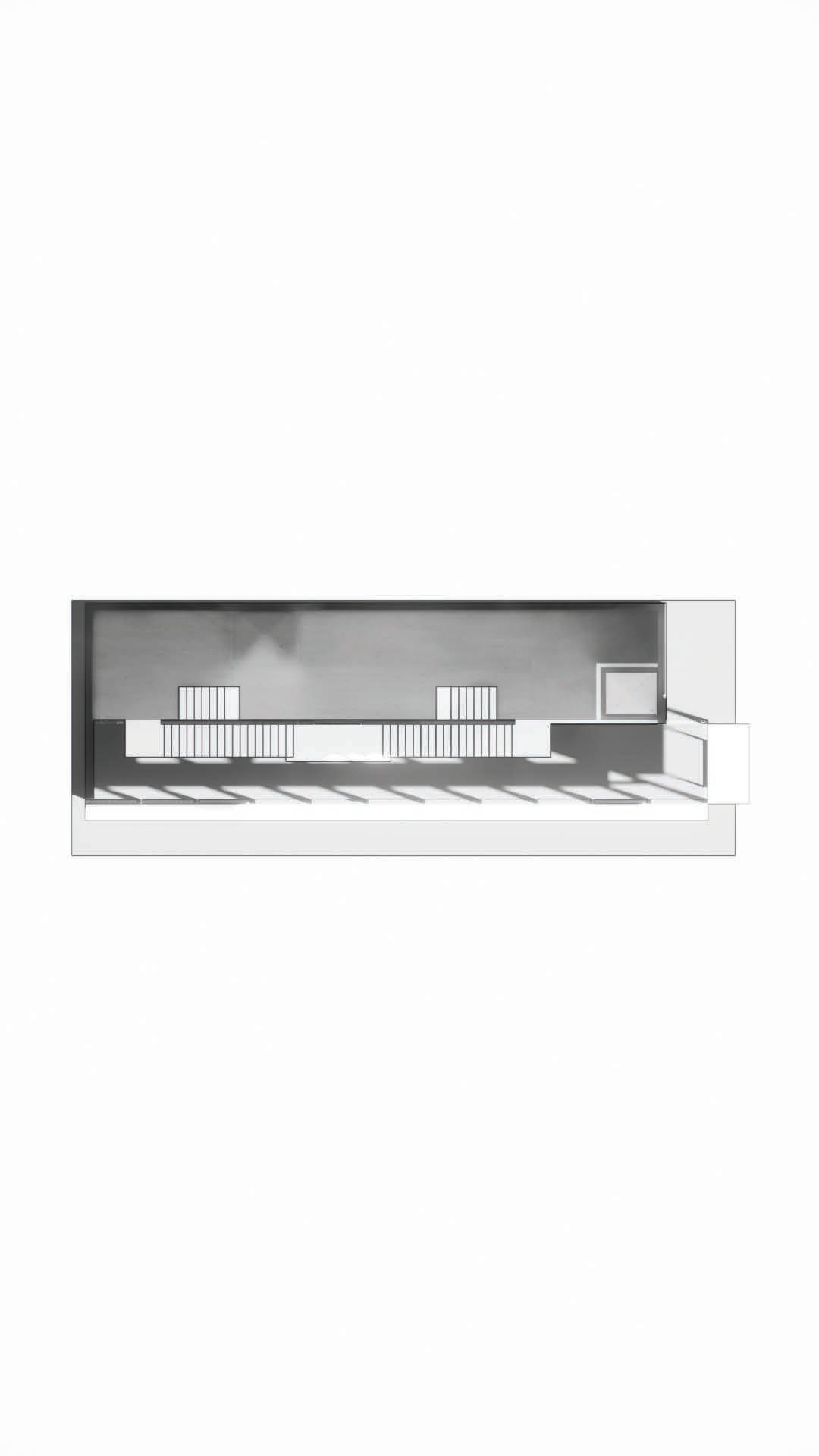
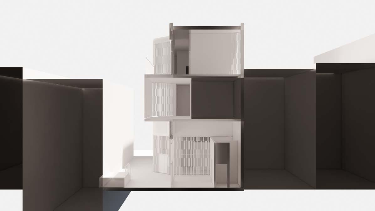
TRANSVERSE SECTION 1
DESIGN INTEGRATION Fall 2023
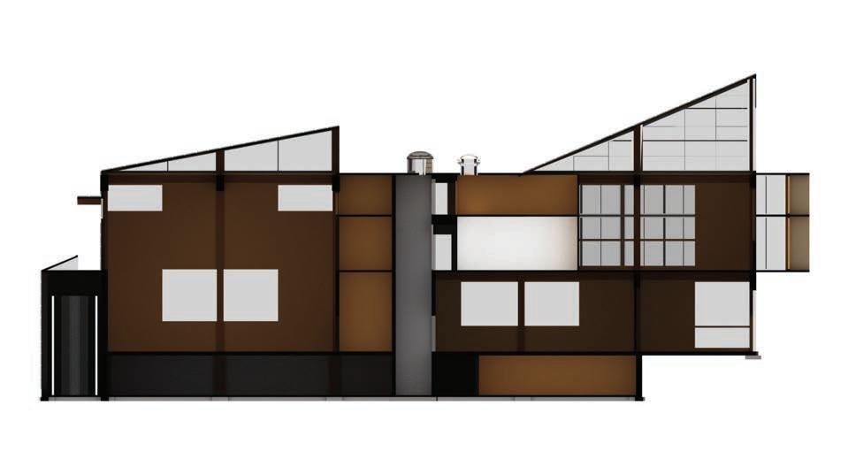
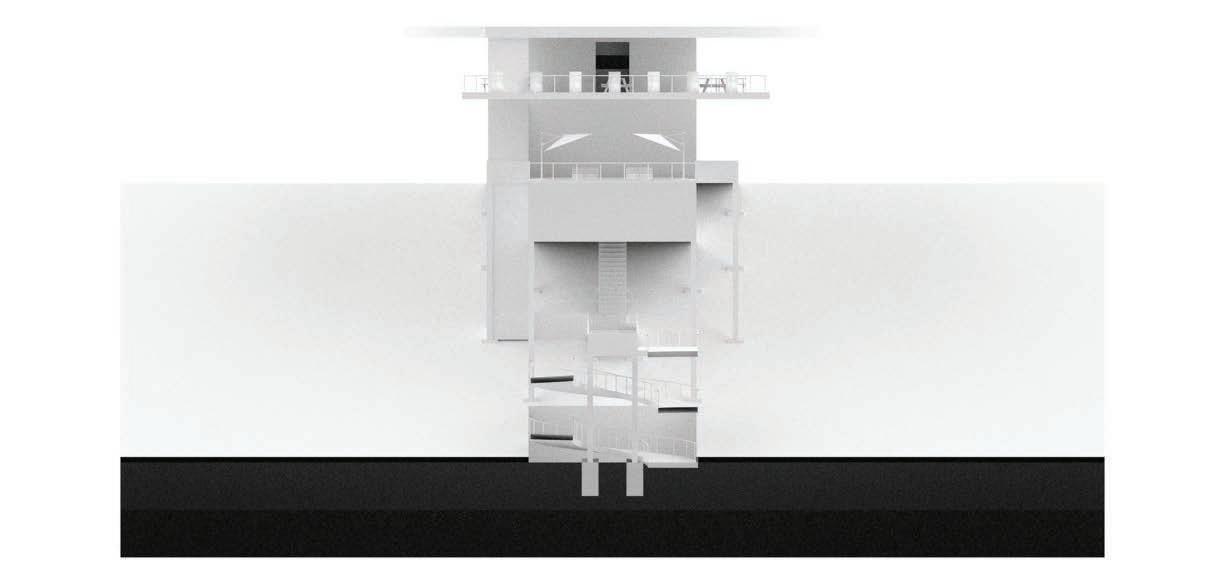
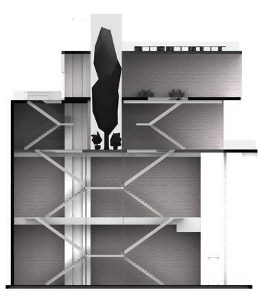
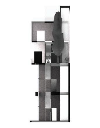
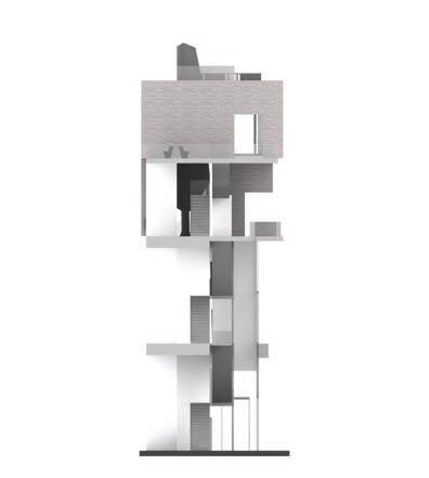
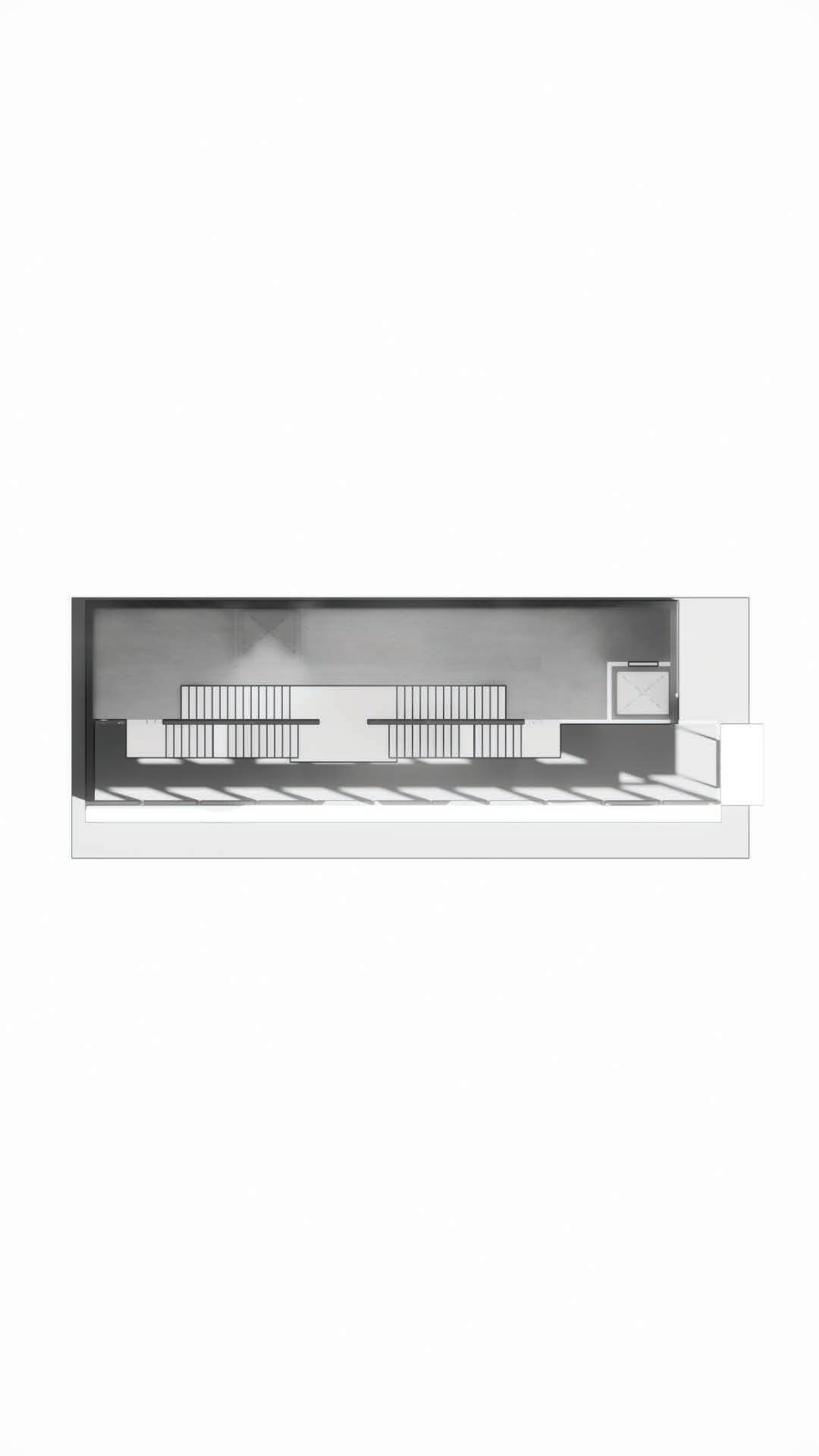
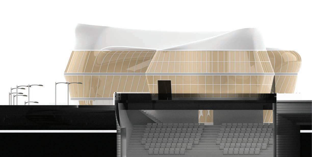
TRANSVERSE SECTION 2
DESIGN INTEGRATION Fall 2023
DESIGN INTEGRATION Fall 2023
DESIGN INTEGRATION Fall 2023
Purpose
Service Served Neutral
DESIGN INTEGRATION Fall 2023
DESIGN INTEGRATION Fall 2023
DESIGN INTEGRATION Fall 2023
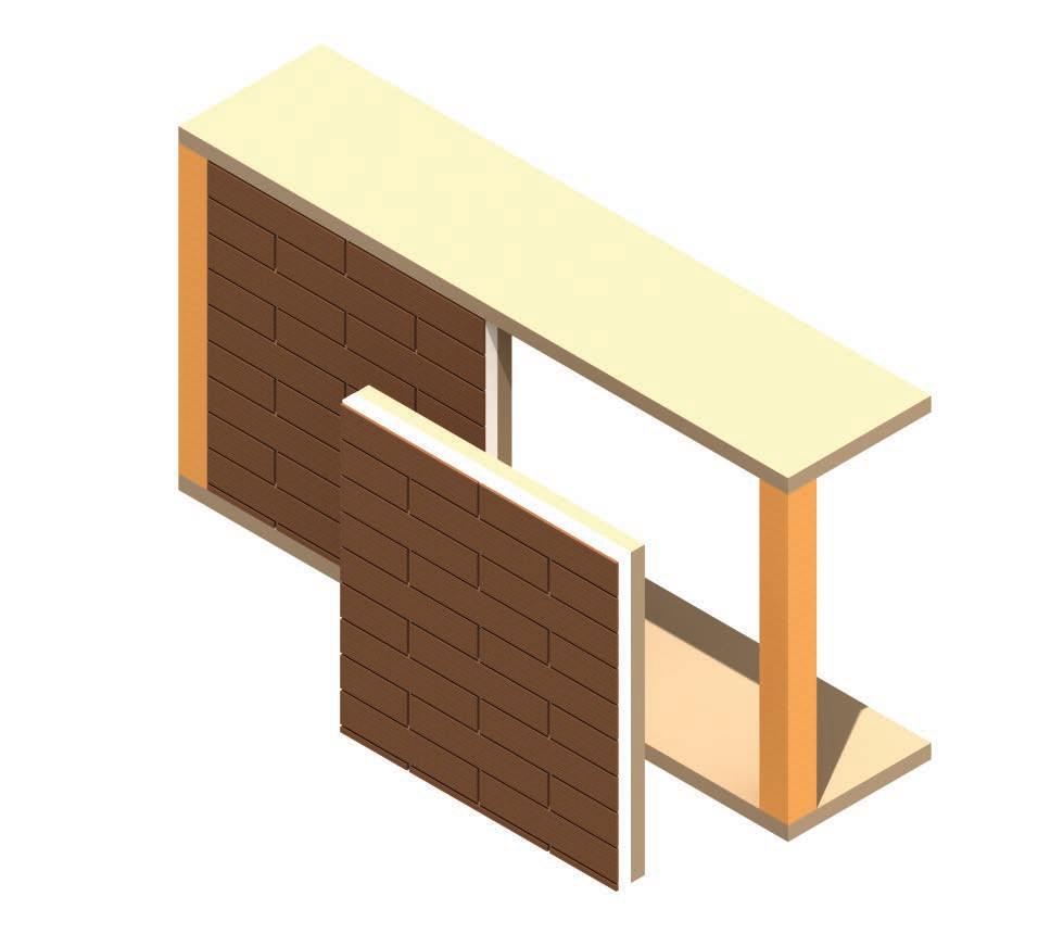
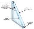
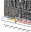
Detail Vertical Section
DESIGN INTEGRATION Fall 2023
Panels
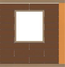
VISION
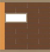
CLERESTORY
DESIGN INTEGRATION Fall 2023
5 ply CLT
Wood Fibre
Insulation R-31 Value
Plywood Sheathing
Drainage Vent
Oak Wood Exterior


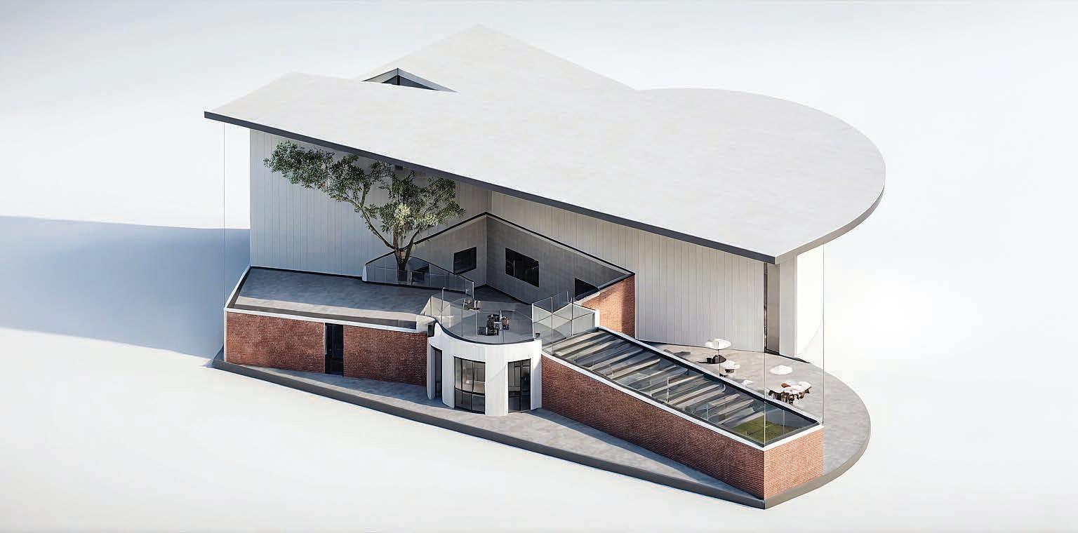
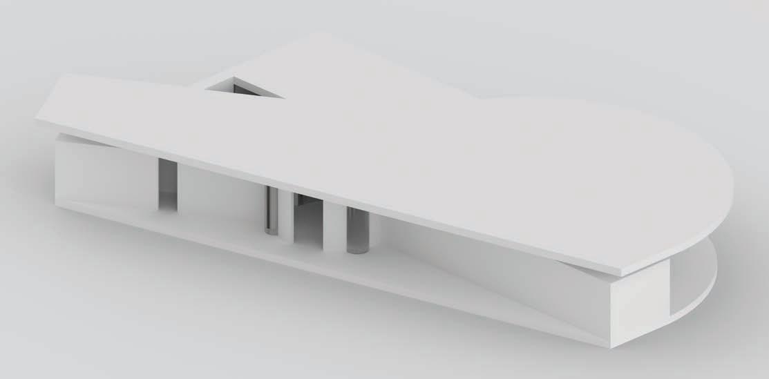
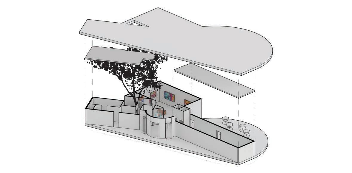
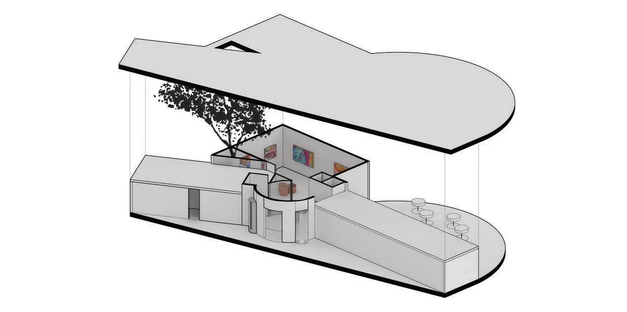
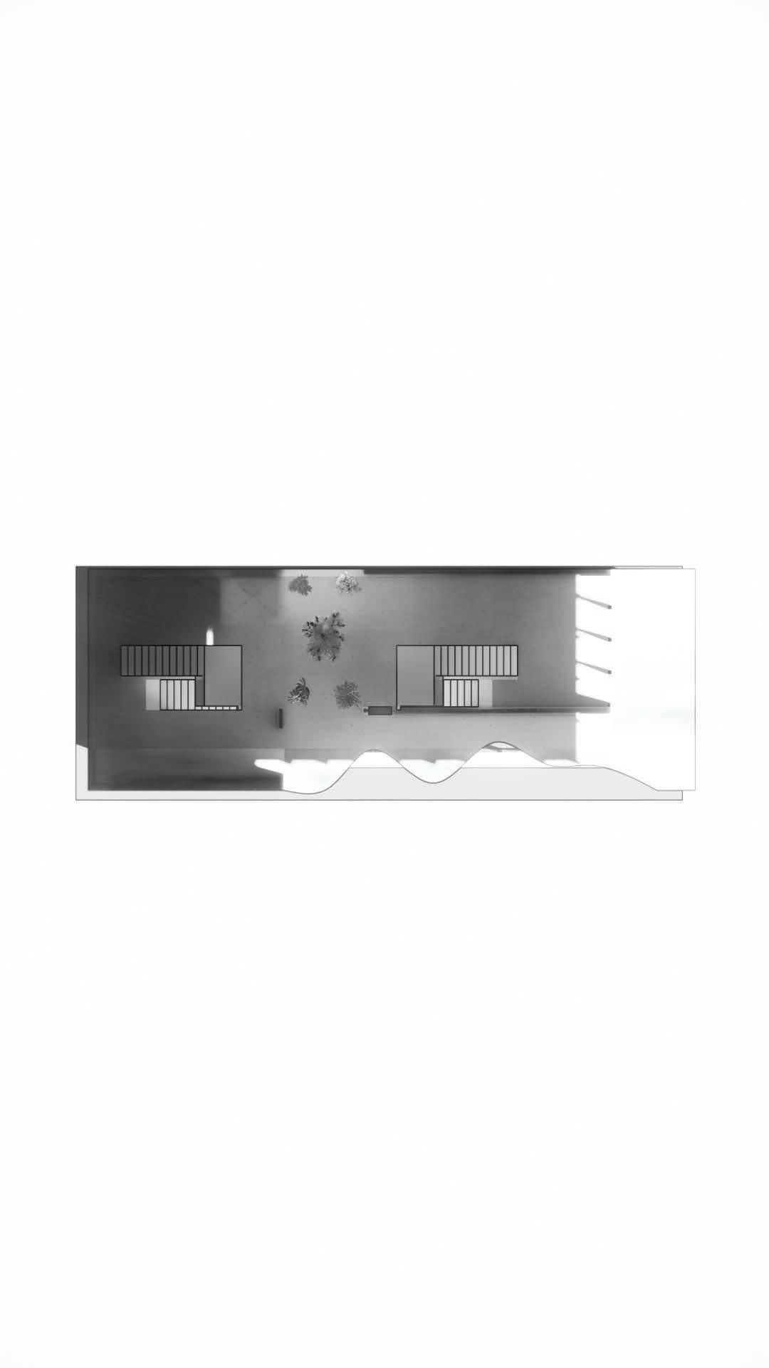
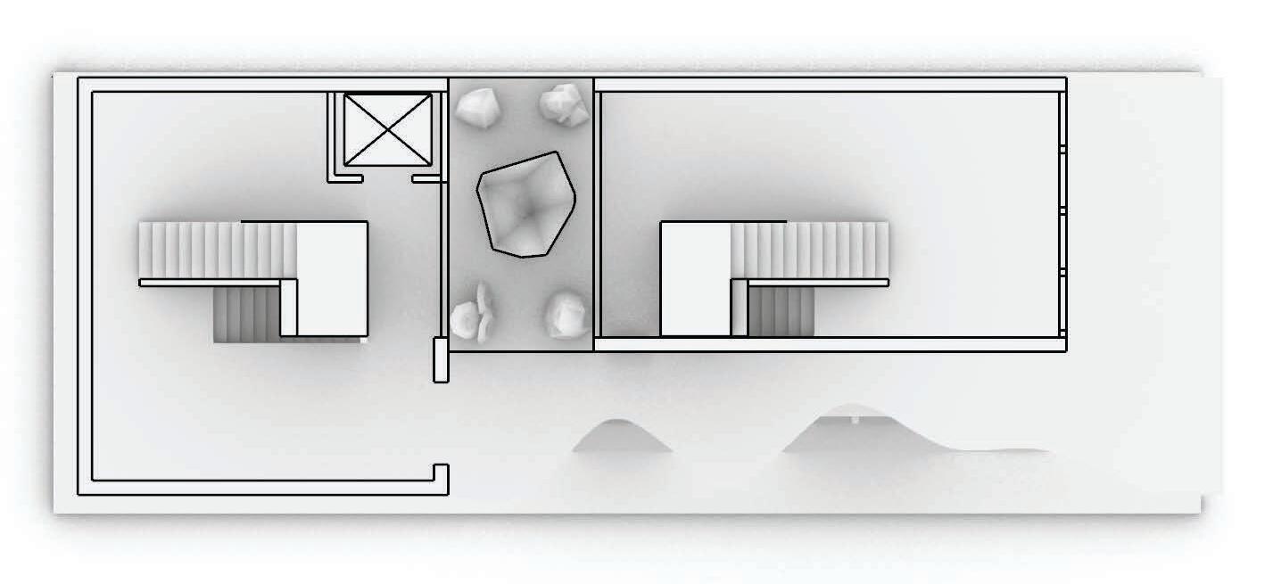
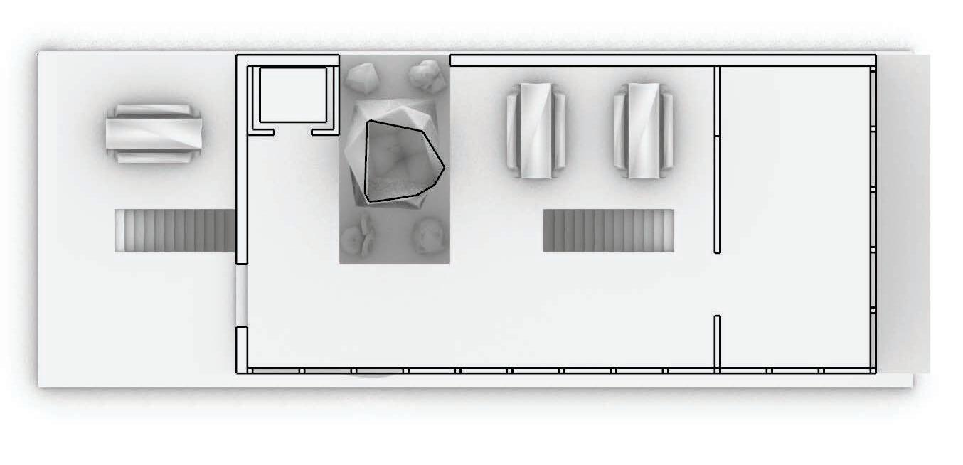
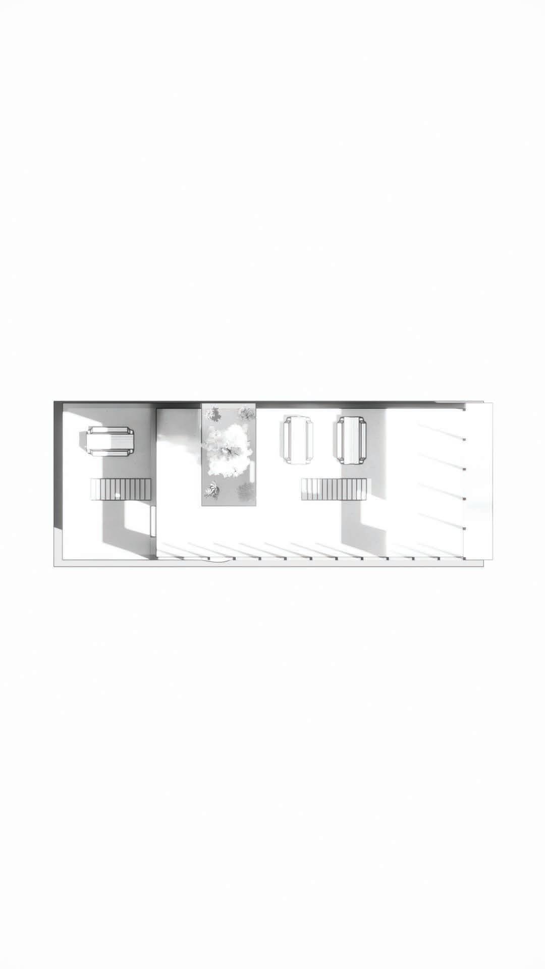
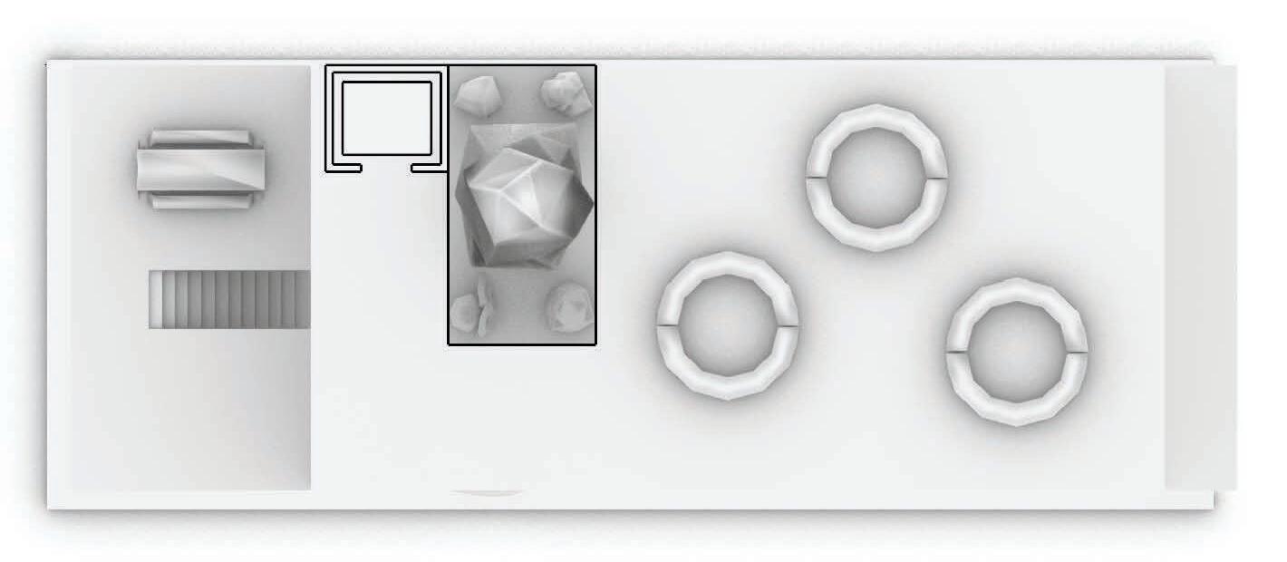
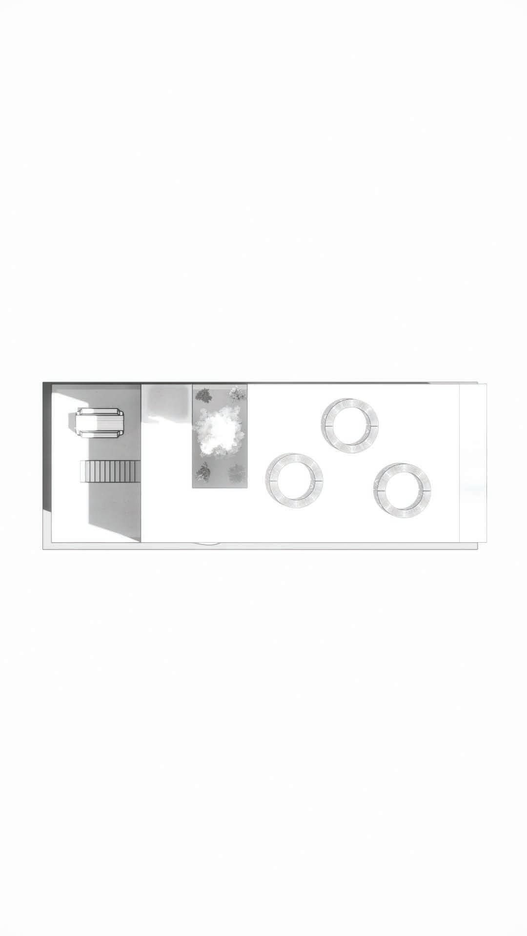
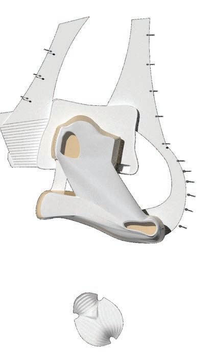
The building’s design revolves around a central circular space where all elements converge. I explored new geometries to enhance flow and space, using subtle shapes rather than precise outlines. The circle, inspired by the infinity sign, introduced fluidity, while feedback helped me transform dead spaces into design opportunities. Overall, the project allowed me to experiment freely and gain valuable design insights.
INTERSECT & CURVE Fall 2022
INTERSECT & CURVE Fall 2022

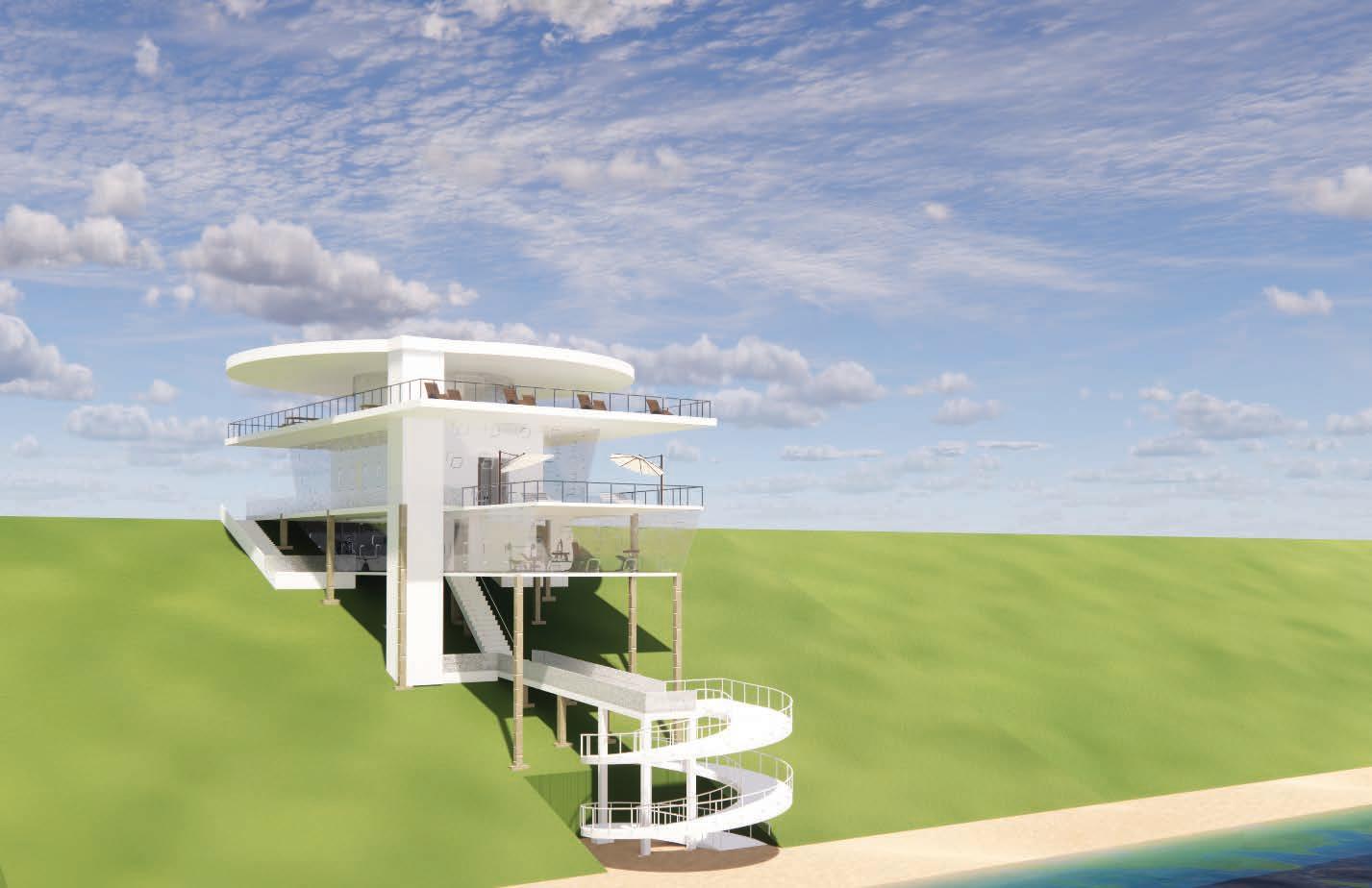
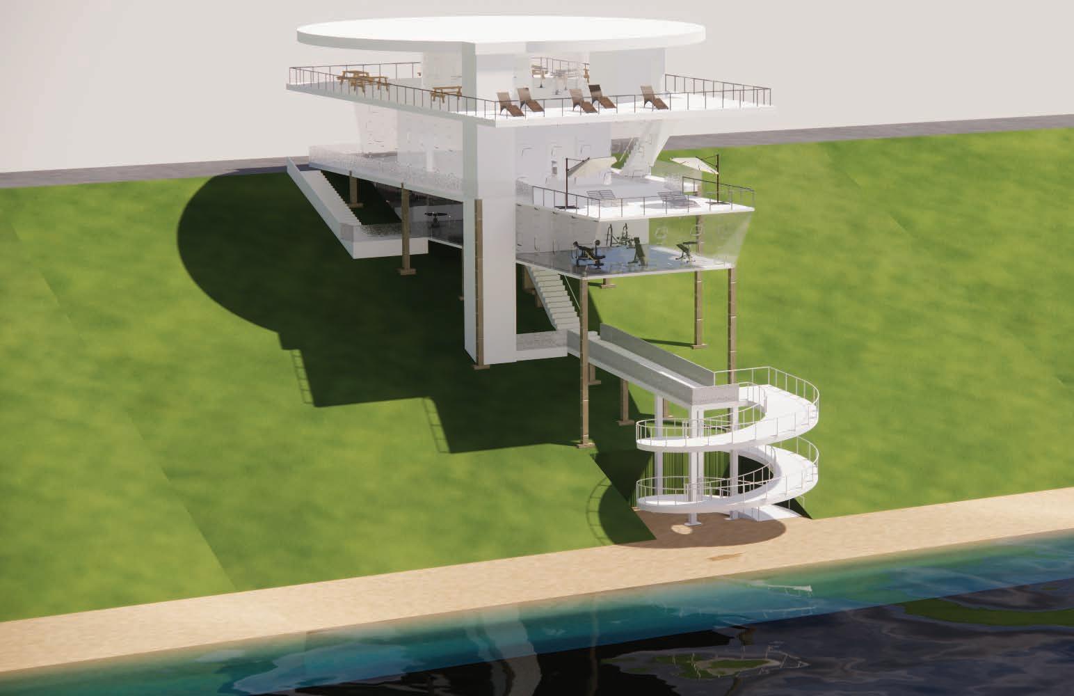
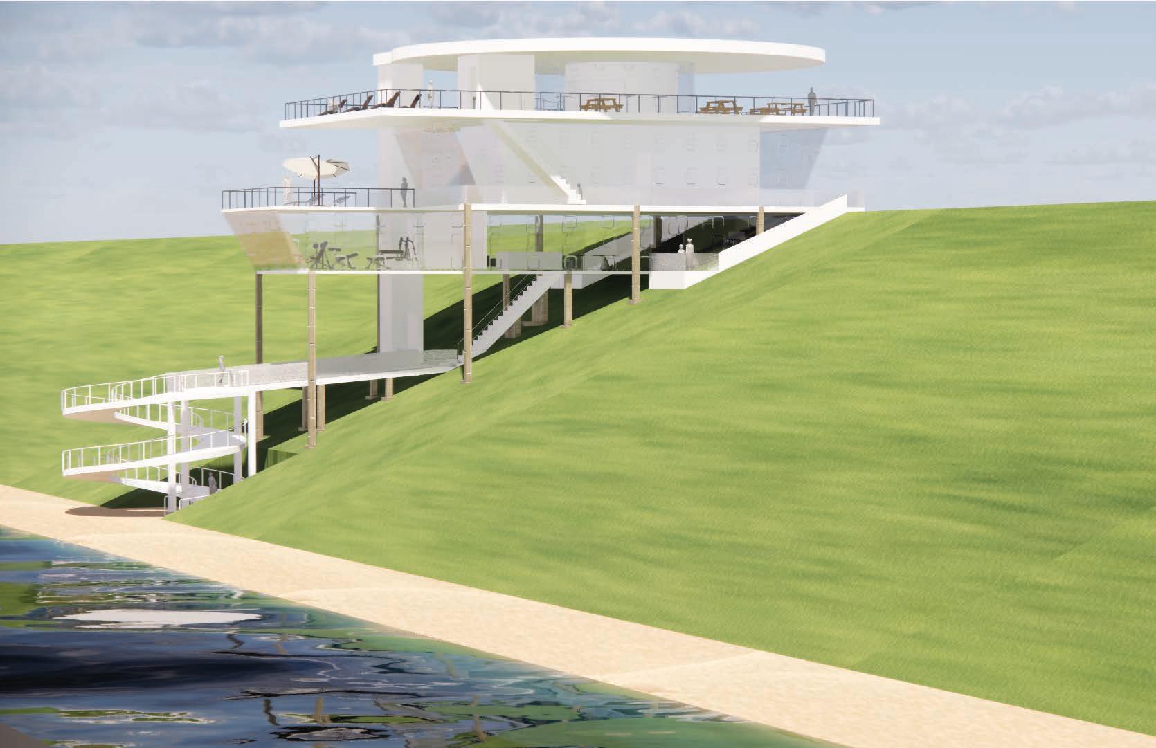
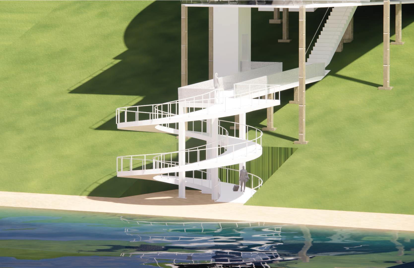
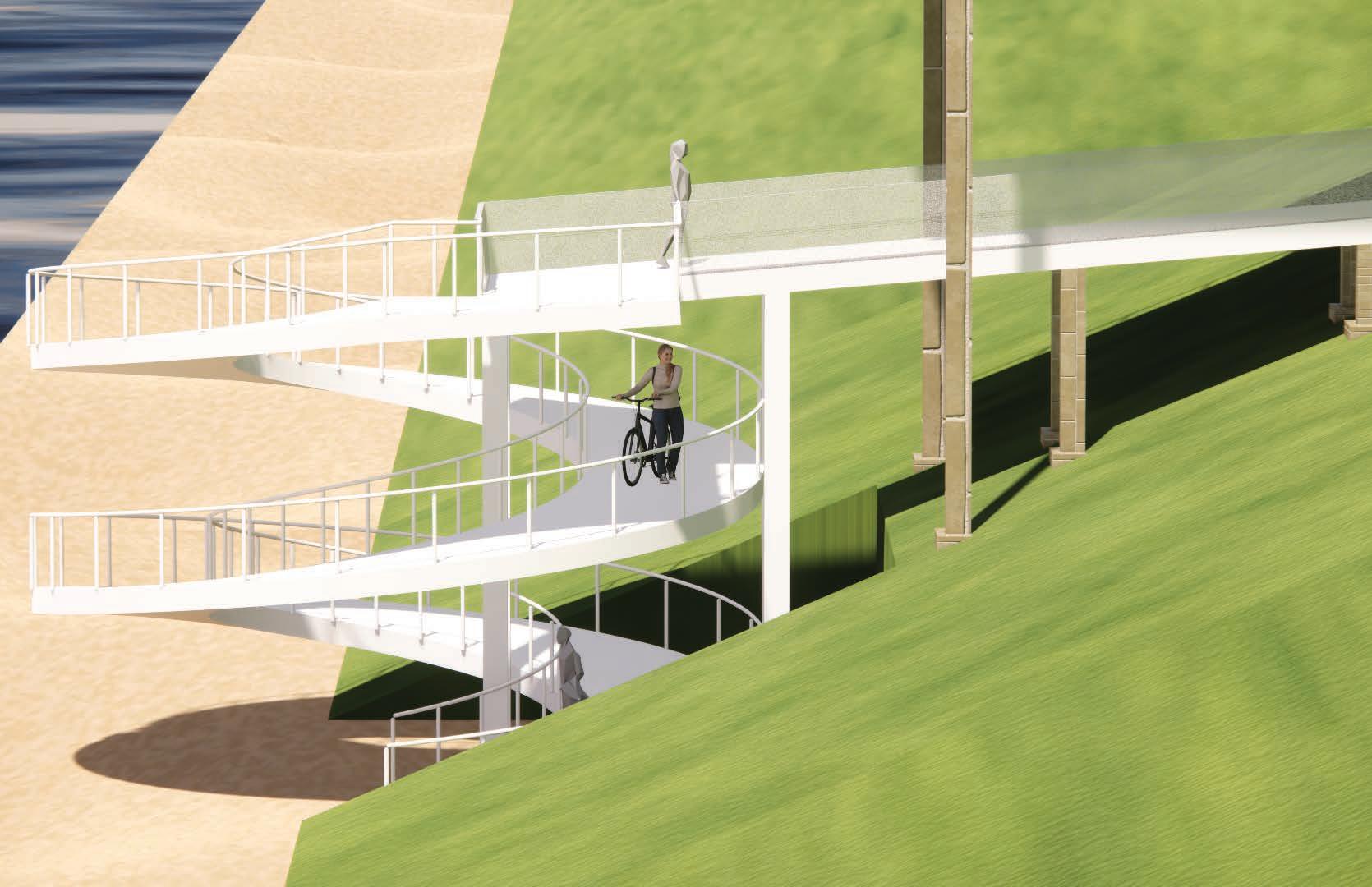
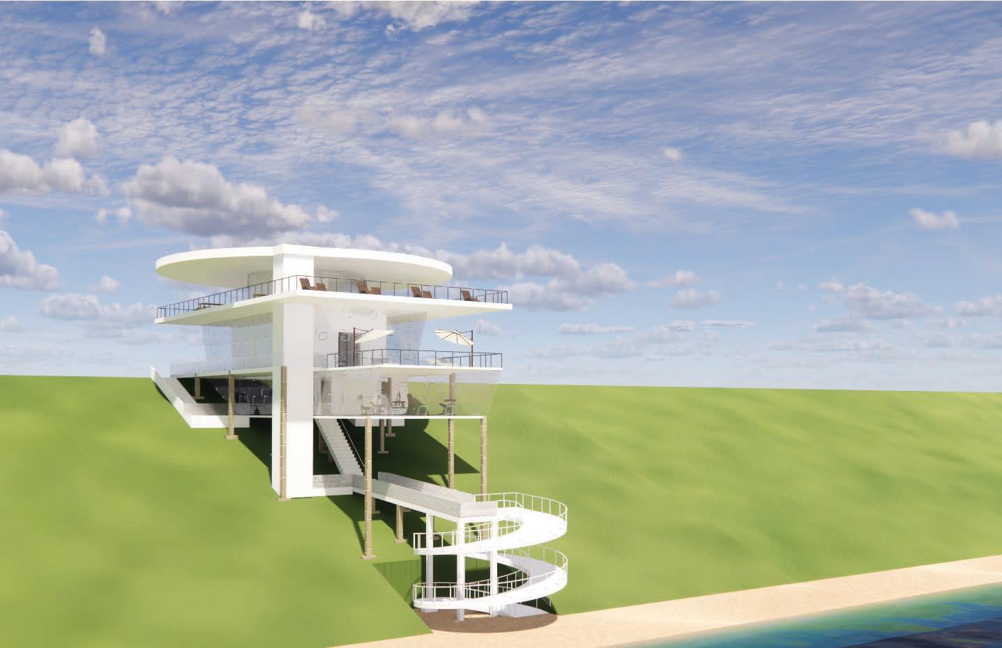
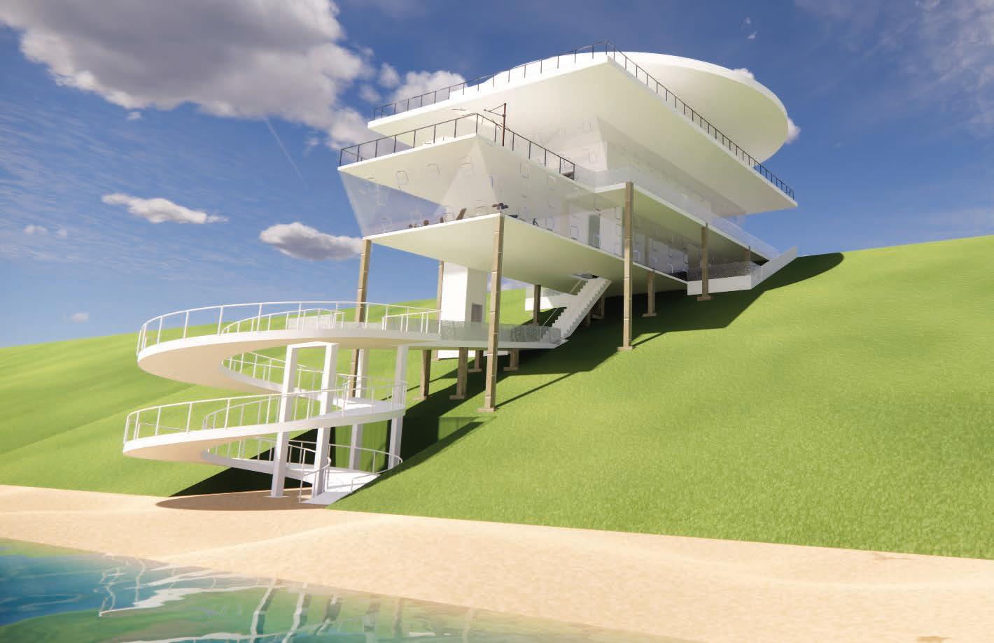
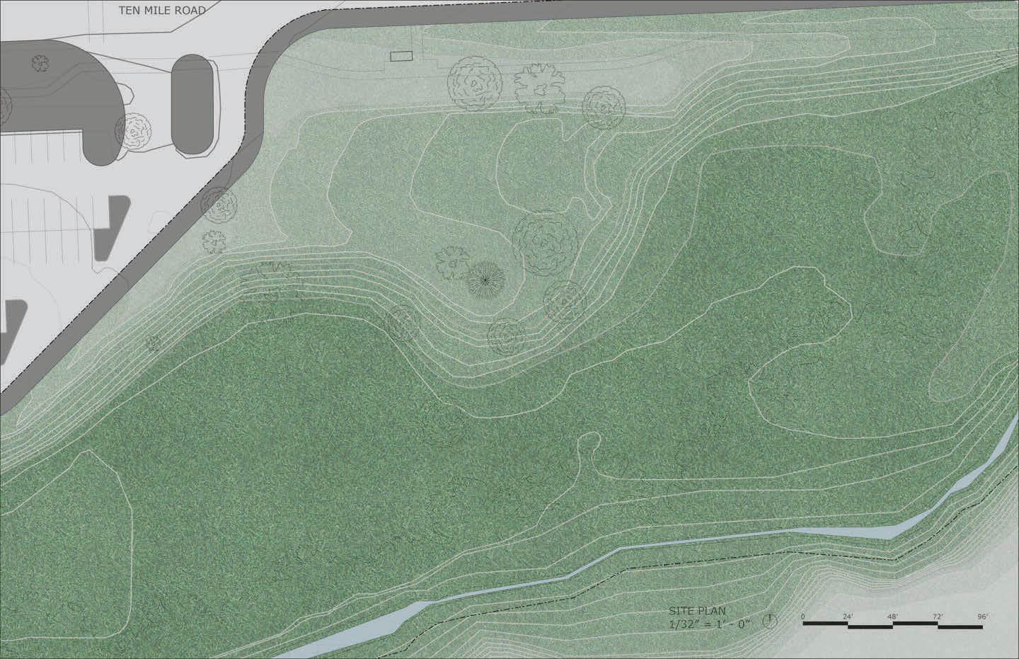
This project challenged me to integrate the building with the landscape, guiding visitors toward the beach. While I aimed to enhance the experience, I didn’t fully adapt the landscape to the building. I learned that detailed drawings and centralizing the building would improve clarity and its connection to the site.
TAPERING & NESTING Fall 2022
TAPERING & NESTING Fall 2022
TAPERING & NESTING Fall 2022
TAPERING & NESTING Fall 2022
TAPERING & NESTING Fall 2022
TAPERING & NESTING Fall 2022
TAPERING & NESTING Fall 2022
TAPERING & NESTING Fall 2022
TAPERING & NESTING Fall 2022
& NESTING
TAPERING & NESTING Fall 2022
TAPERING & NESTING Fall 2022
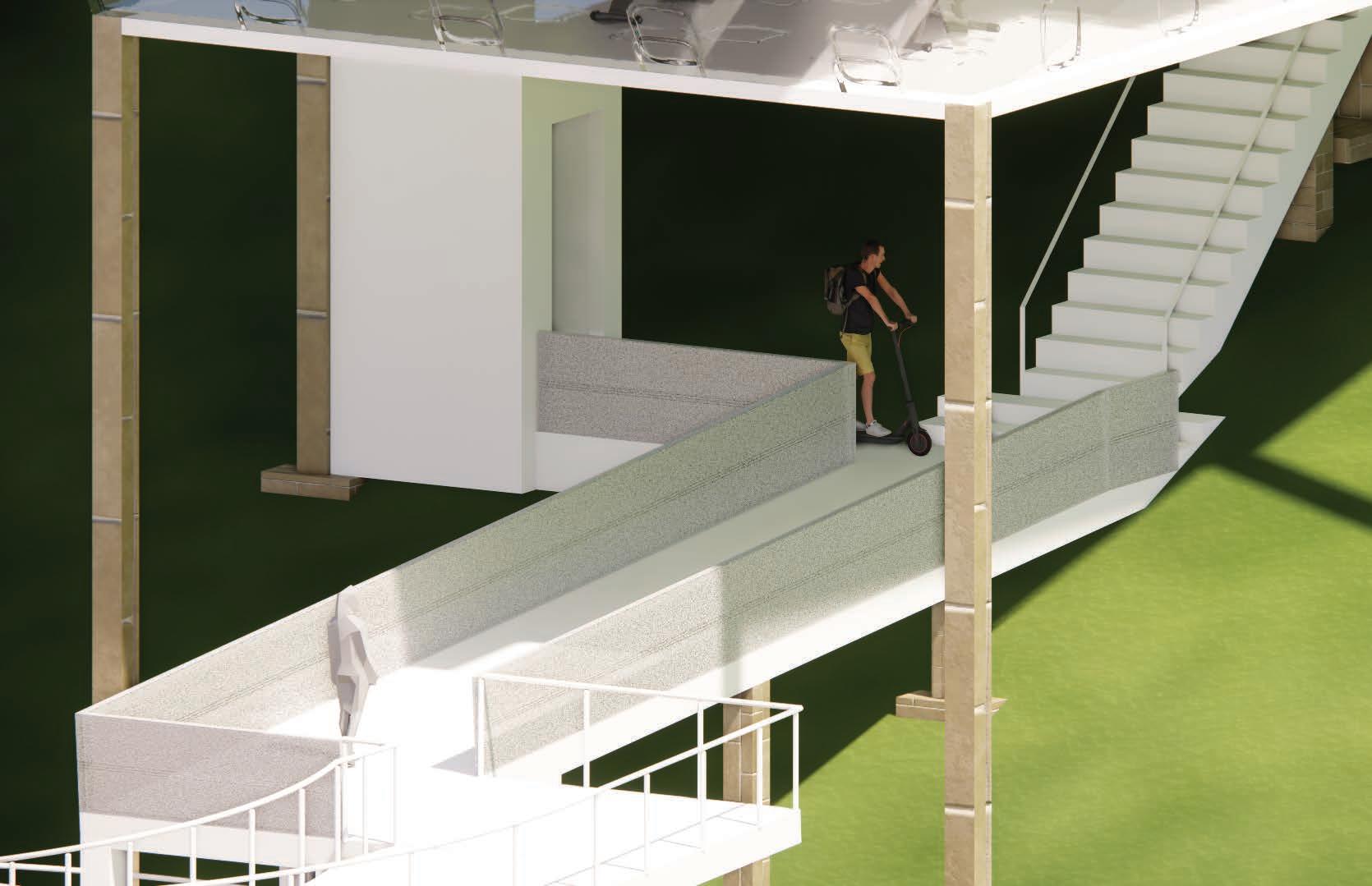
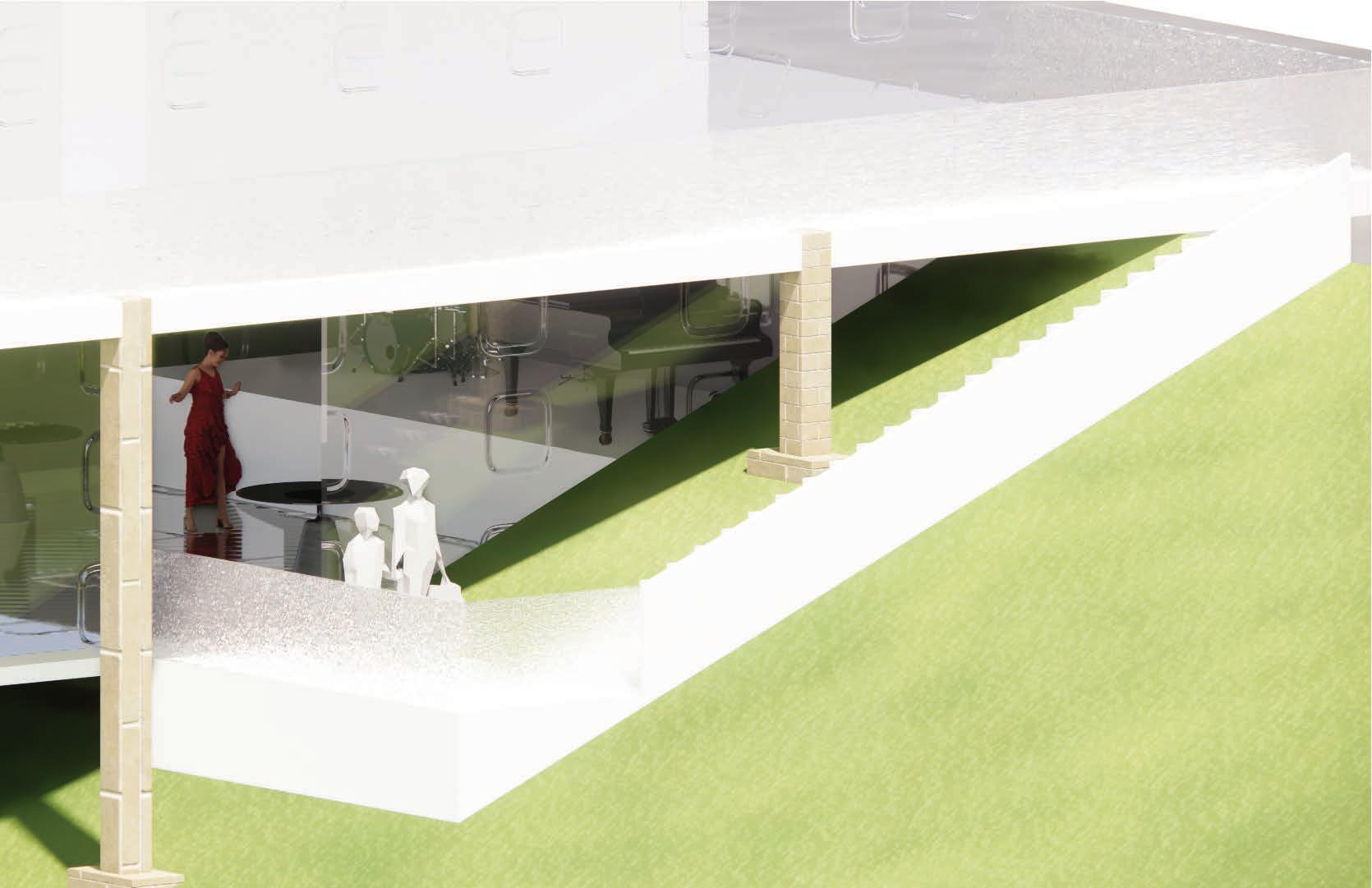
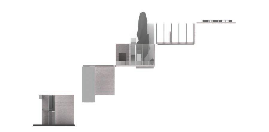
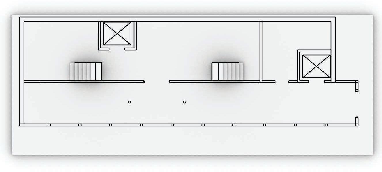
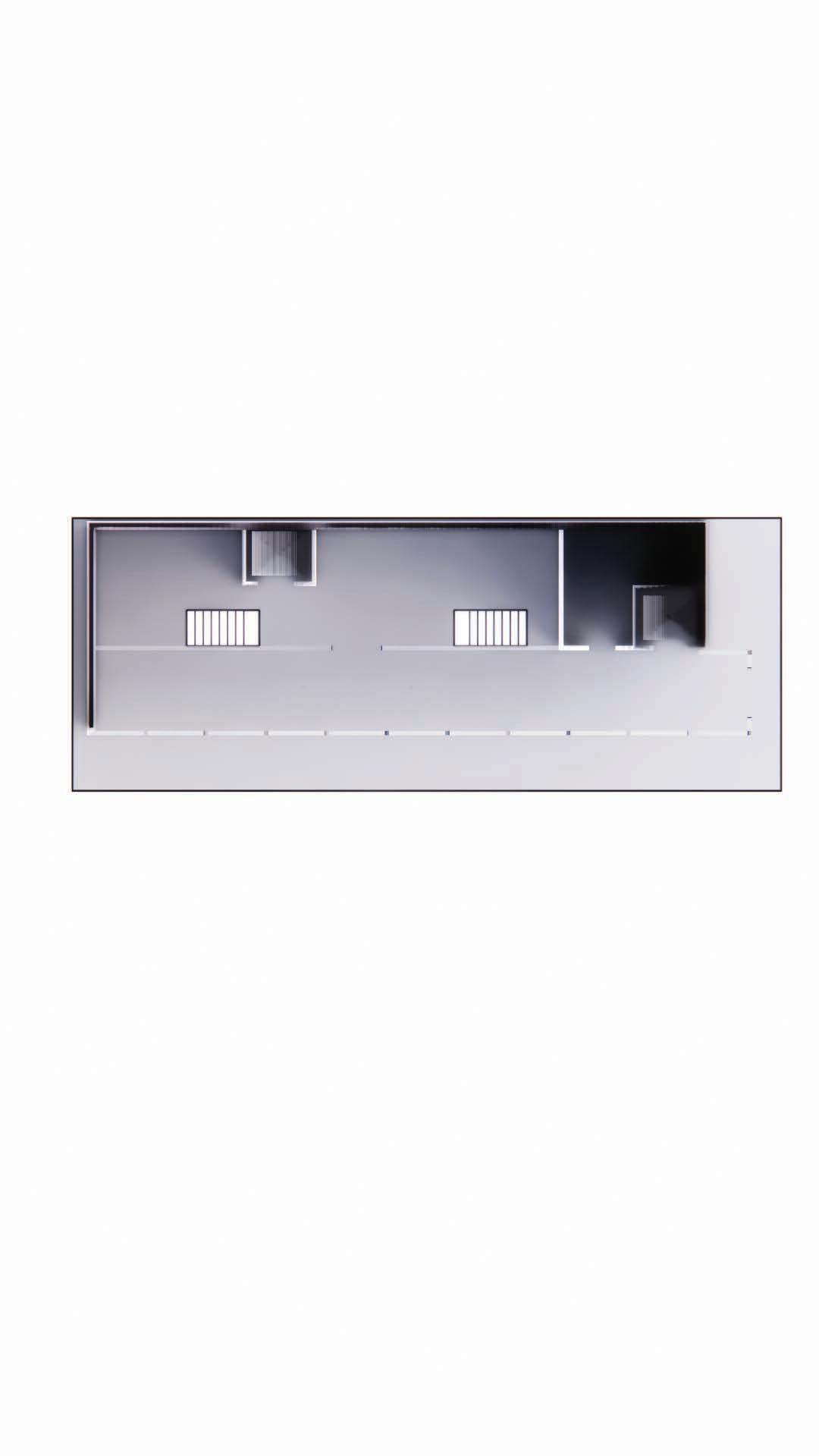
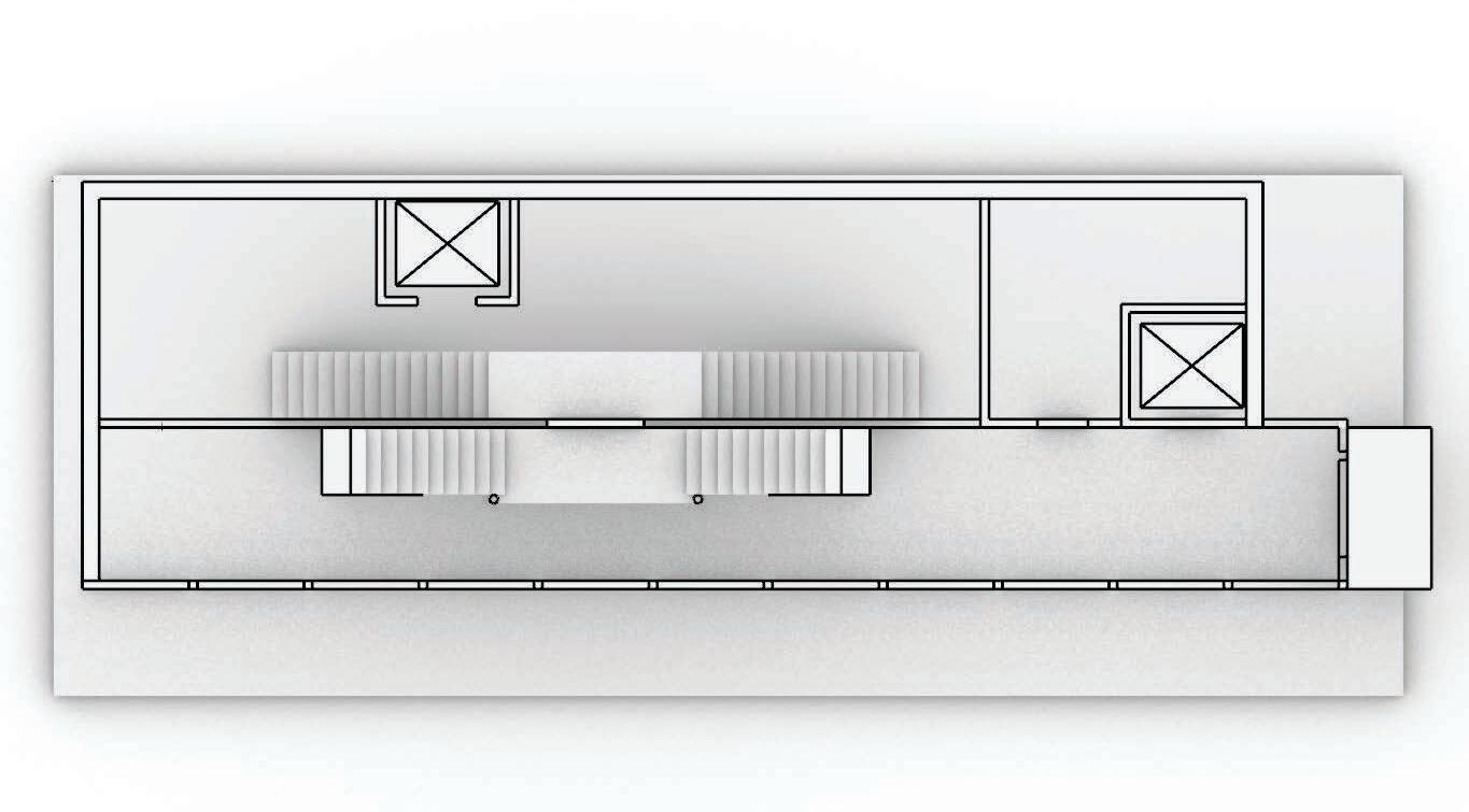
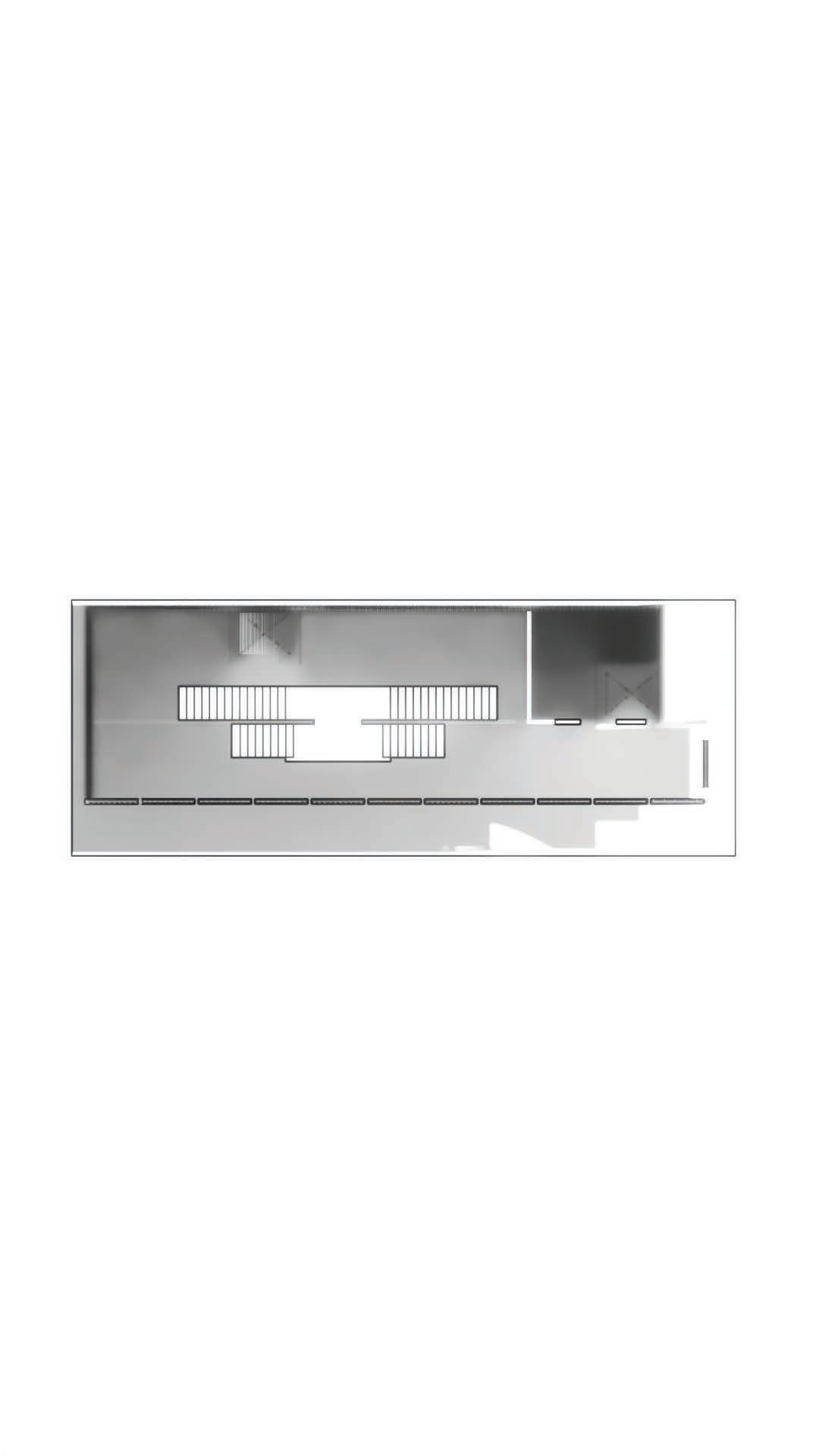
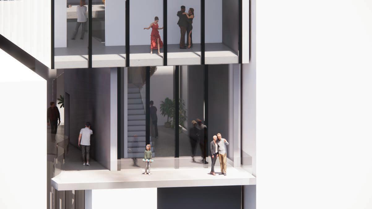
The building uses overlapping rectangular prisms to create unique spaces with uneven volumes. The central staircase is both a key feature and functional element, but its size and the varying ceiling heights created design challenges. If approached differently, I’d define the floor volumes and ceiling heights more clearly to improve space accessibility. This allows better integration with surrounding spaces.
Uneven Overlay
Uneven Levels
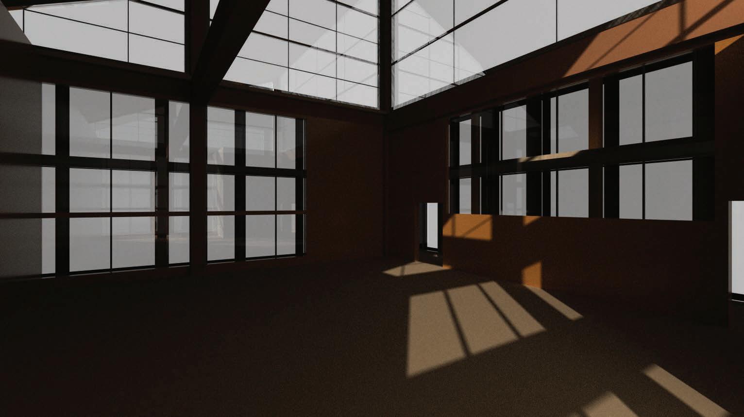
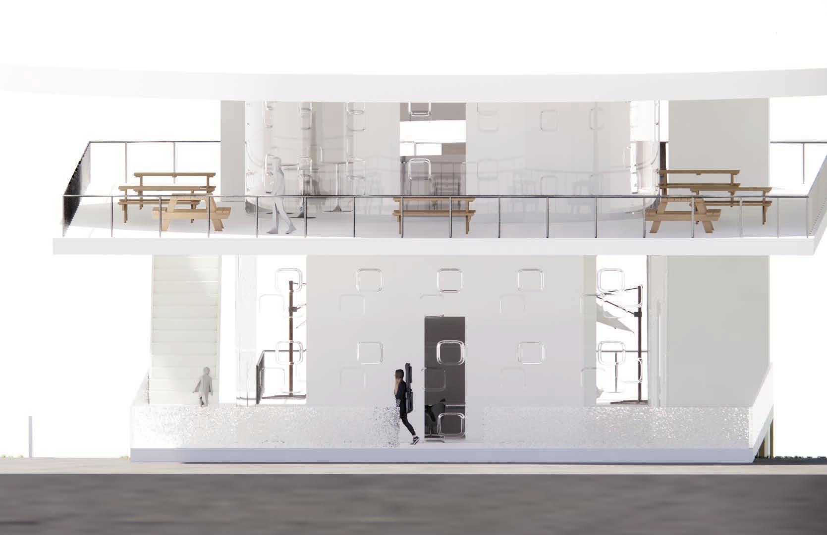
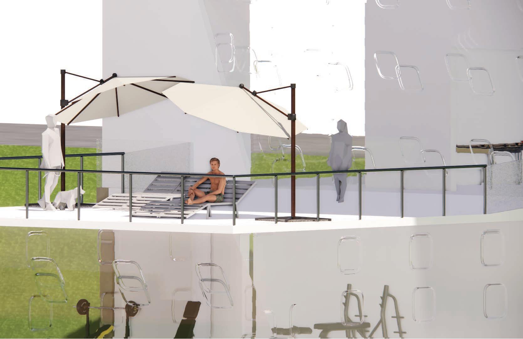
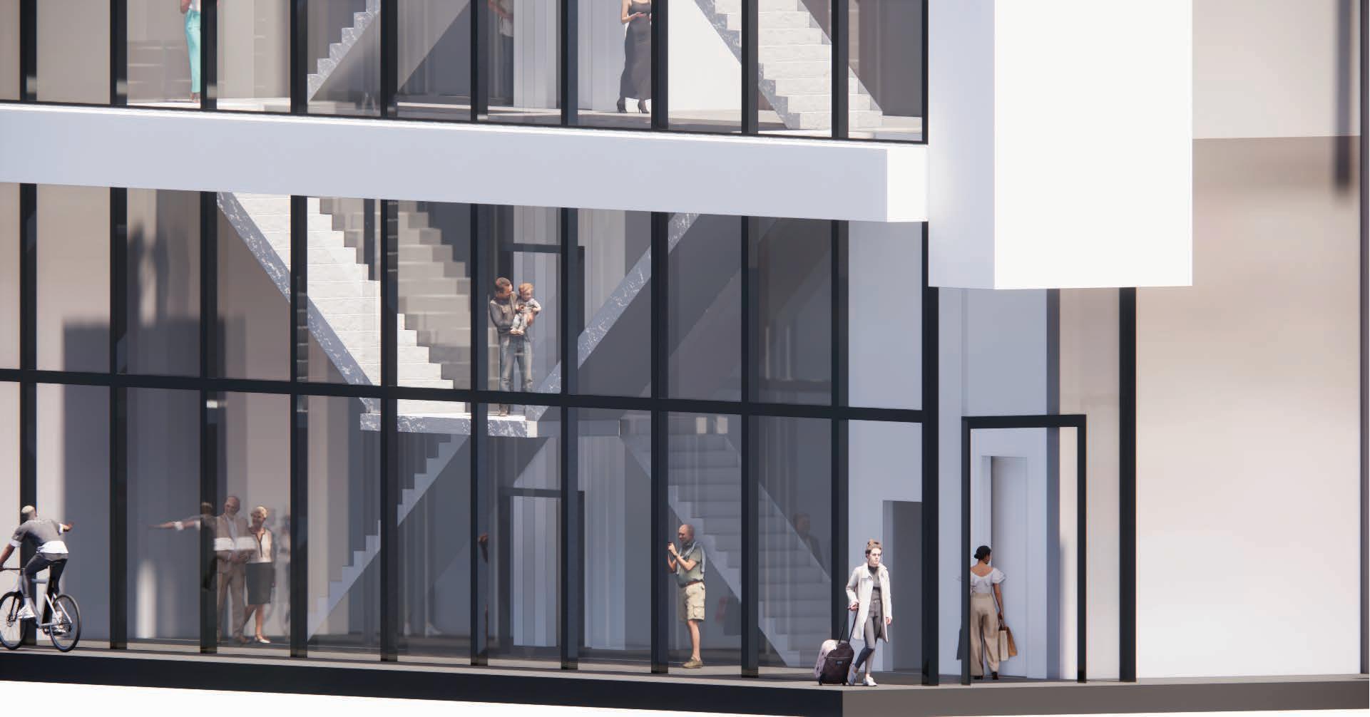
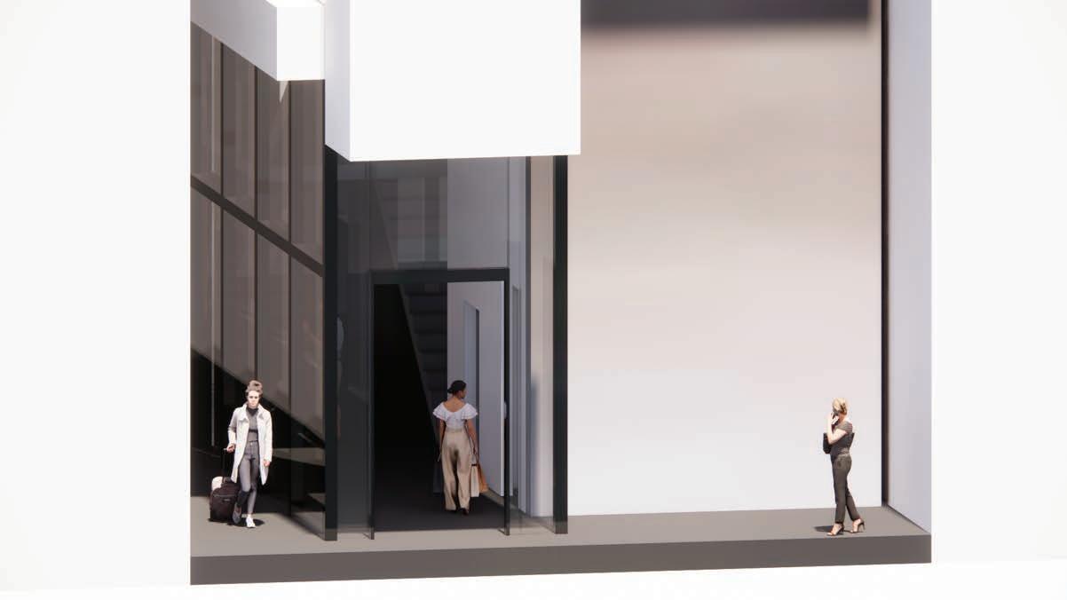
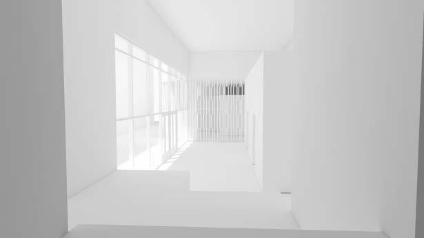
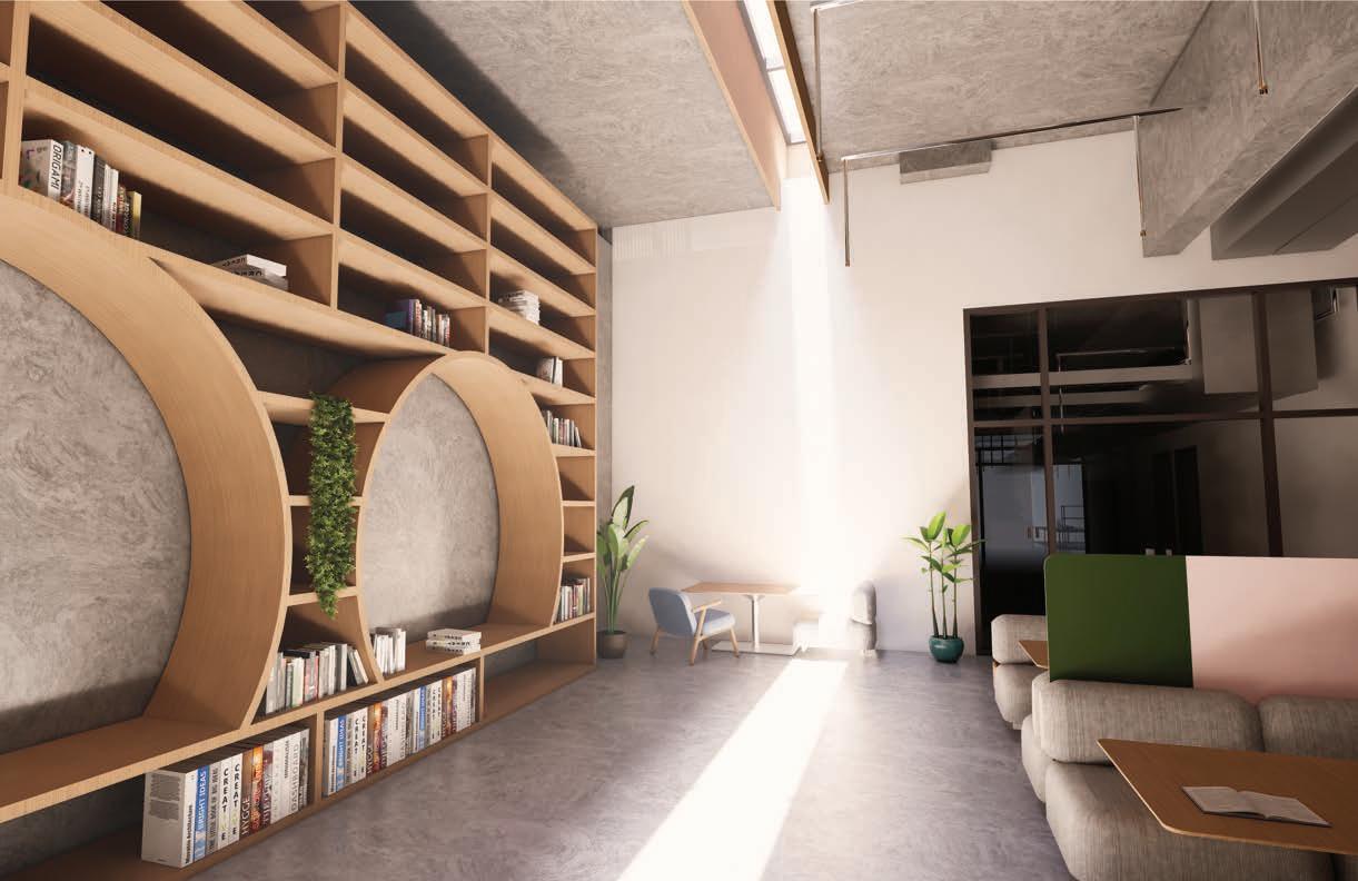
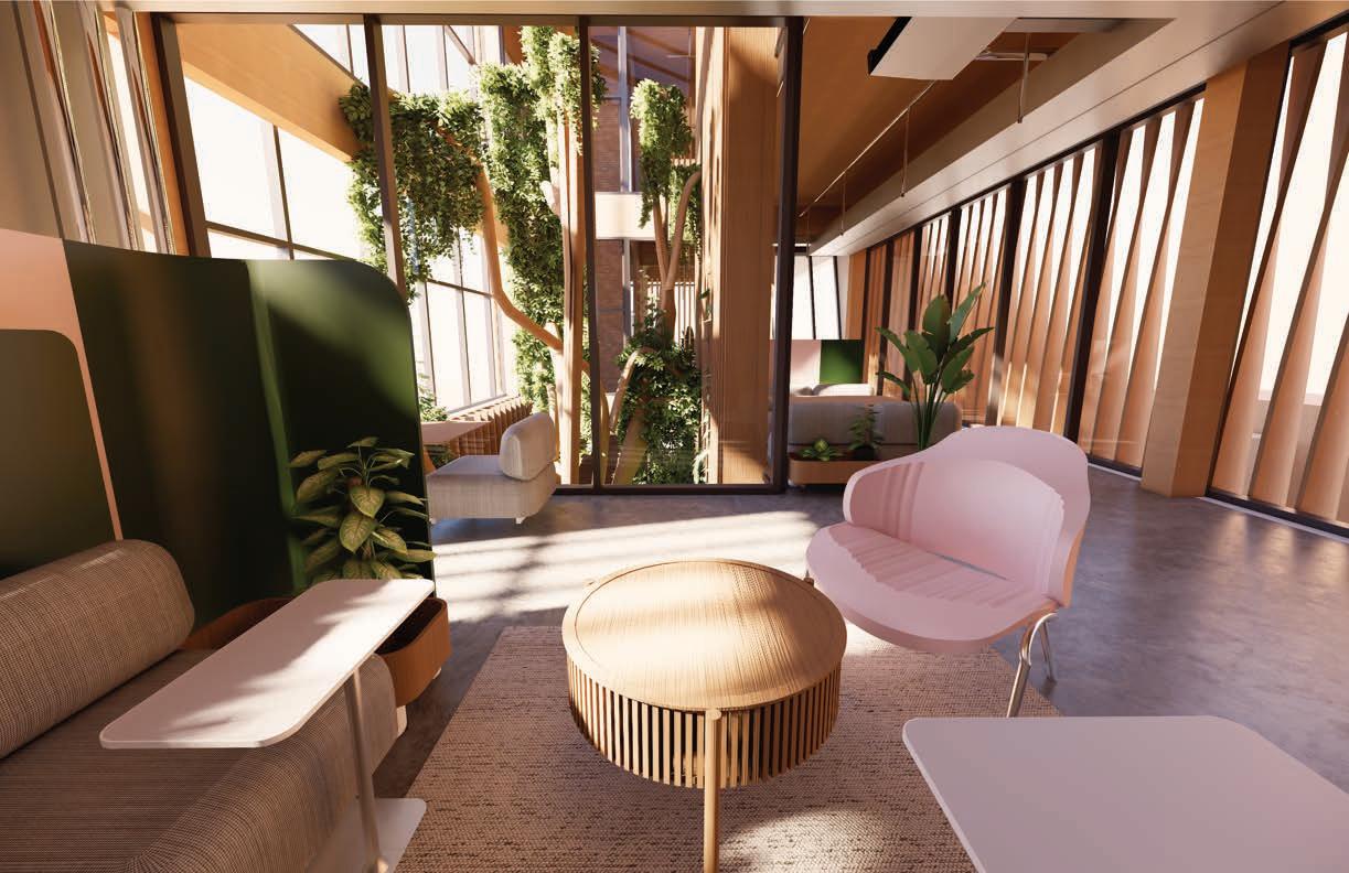
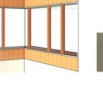
more light due to glass windows
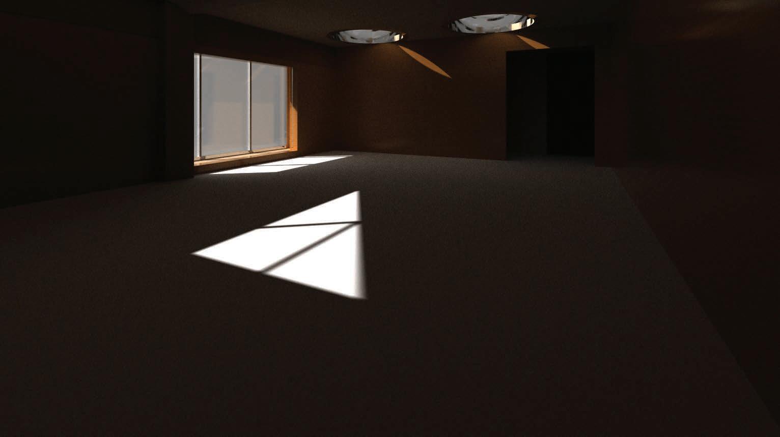
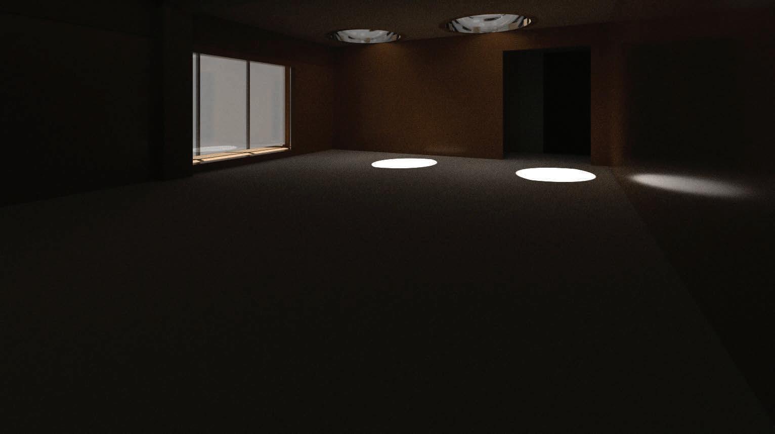
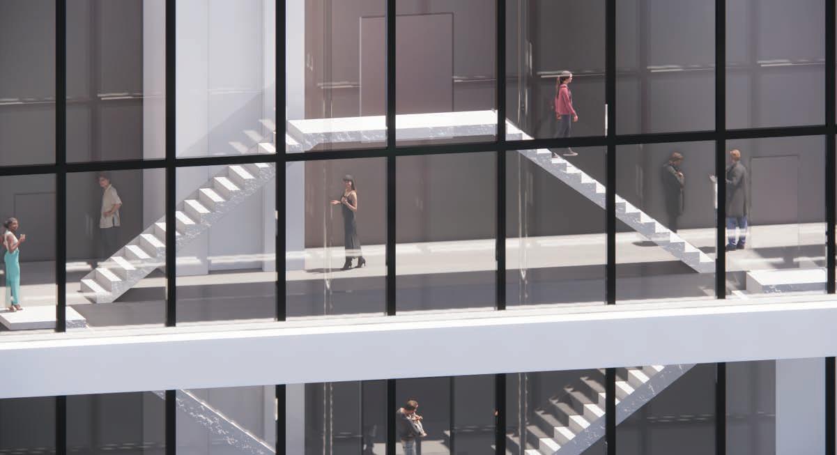
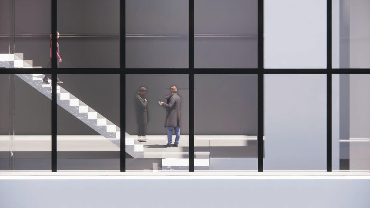
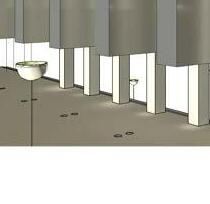
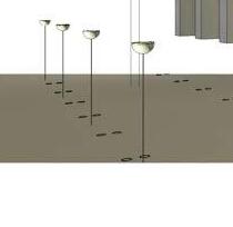
The existence of the buildings that surrounds this building means that the flow of natural light is limited. Especially when the other buildings are at tall heights. The usage of glass to create a transparent building means the views should be accessible and clear. The above render shows the natural light flow and how much artificial light would be necessary to create the desired view
VERTICALITY Spring 2023
VERTICALITY Spring 2023

VERTICALITY Spring 2023

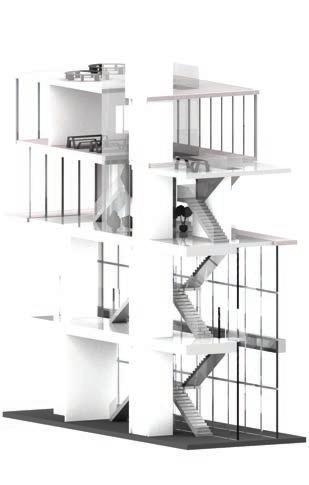
Rendered Stairway VERTICALITY Spring 2023


Main Elevator
Hidden Brick Wall
Rendered Without Brick Walls
VERTICALITY Spring 2023
VERTICALITY Spring 2023
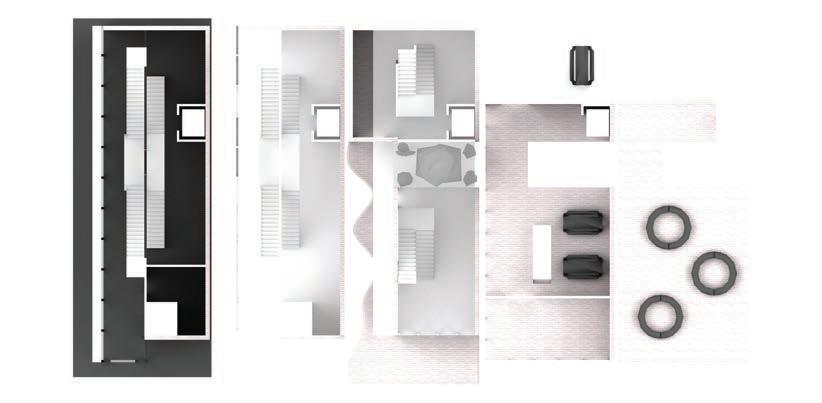
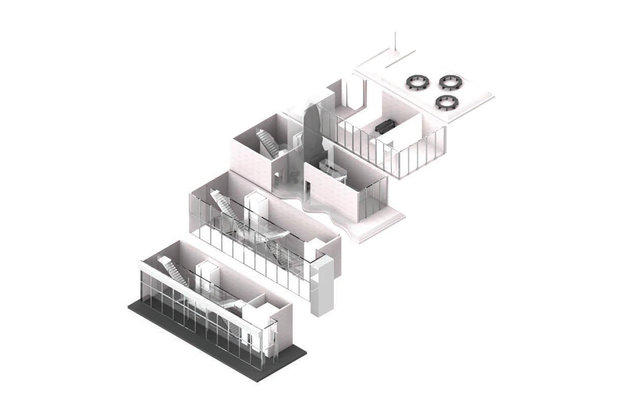
First Floor Lower
VERTICALITY Spring 2023
First Floor Upper
VERTICALITY Spring 2023
Second Floor Lower
Second Floor Upper
VERTICALITY Spring 2023
Third Floor
Fourth Floor
VERTICALITY Spring 2023
VERTICALITY

OVERVIEW

The building blends spaces for both social interaction and education, with an emphasis on natural light and accessibility. It avoids orthogonal corners for a more organic design, while balancing the built components. The integration of hanging out areas and classrooms creates a dynamic, welcoming atmosphere. How do the social and educational spaces connect with each other?
IMPERFECT REACH Fall 2022
IMPERFECT REACH Fall 2022
Ground Floor
IMPERFECT REACH Fall 2022
IMPERFECT REACH Fall 2022
IMPERFECT REACH Fall 2022
Auditorium
IMPERFECT REACH Fall 2022
IMPERFECT REACH Fall 2022
IMPERFECT REACH Fall 2022
IMPERFECT REACH Fall 2022
IMPERFECT REACH Fall 2022
IMPERFECT REACH Fall 2022
Integrated Design 5 | Team 05
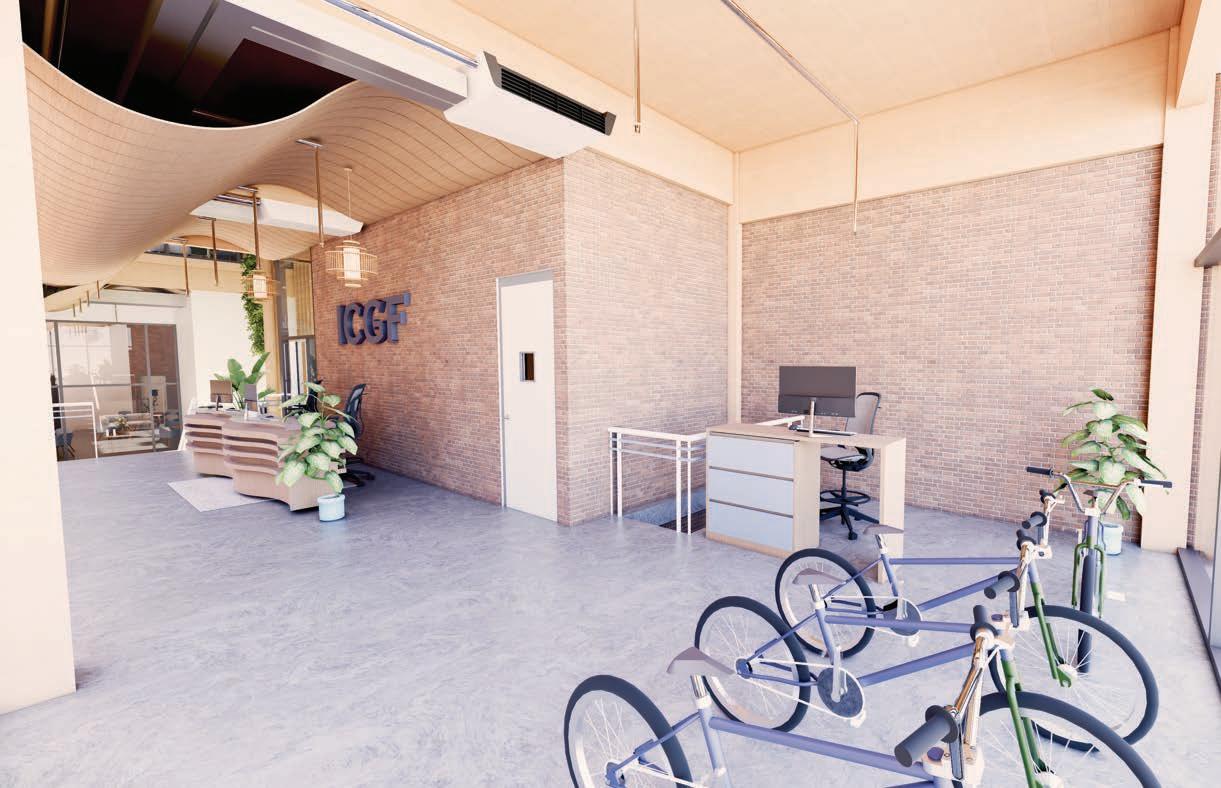
“For international students having a bike gives them freedom because of how confusing public busing is for them”


Emily Thompson
The design on the mesh facade on the exterior of the facade makes Carlos feel inspired to help the community and rising needs of international students. Since the Facade allows for vision into his workspace it creates a sense of connection to the rest of the building.
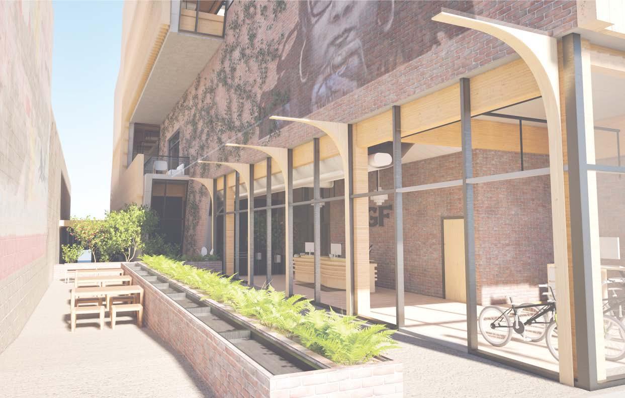
Open event space on the first floor allows for a view into the bike repair shop to instill a connection between the users. The patio space on the side of the building acts as a shared space with Cork and activates the streetfron along the side of the building.
Emily Thompson
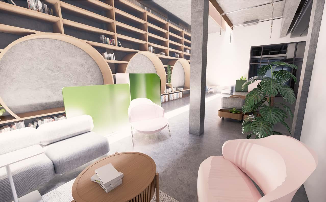
Emily enjoys using the communal lounge to network with her colleagues and gather with fellow residents. Due to the nature of her work, she communicates with fellow residents who are new to Flint and help them search for ways to engage with city settle into

The different co-living spaces, being the workspace, lounge, and kitchen, really offers a space for residents to interact but have a connect through the facade that exists there and the pushing of the program to the exterior.
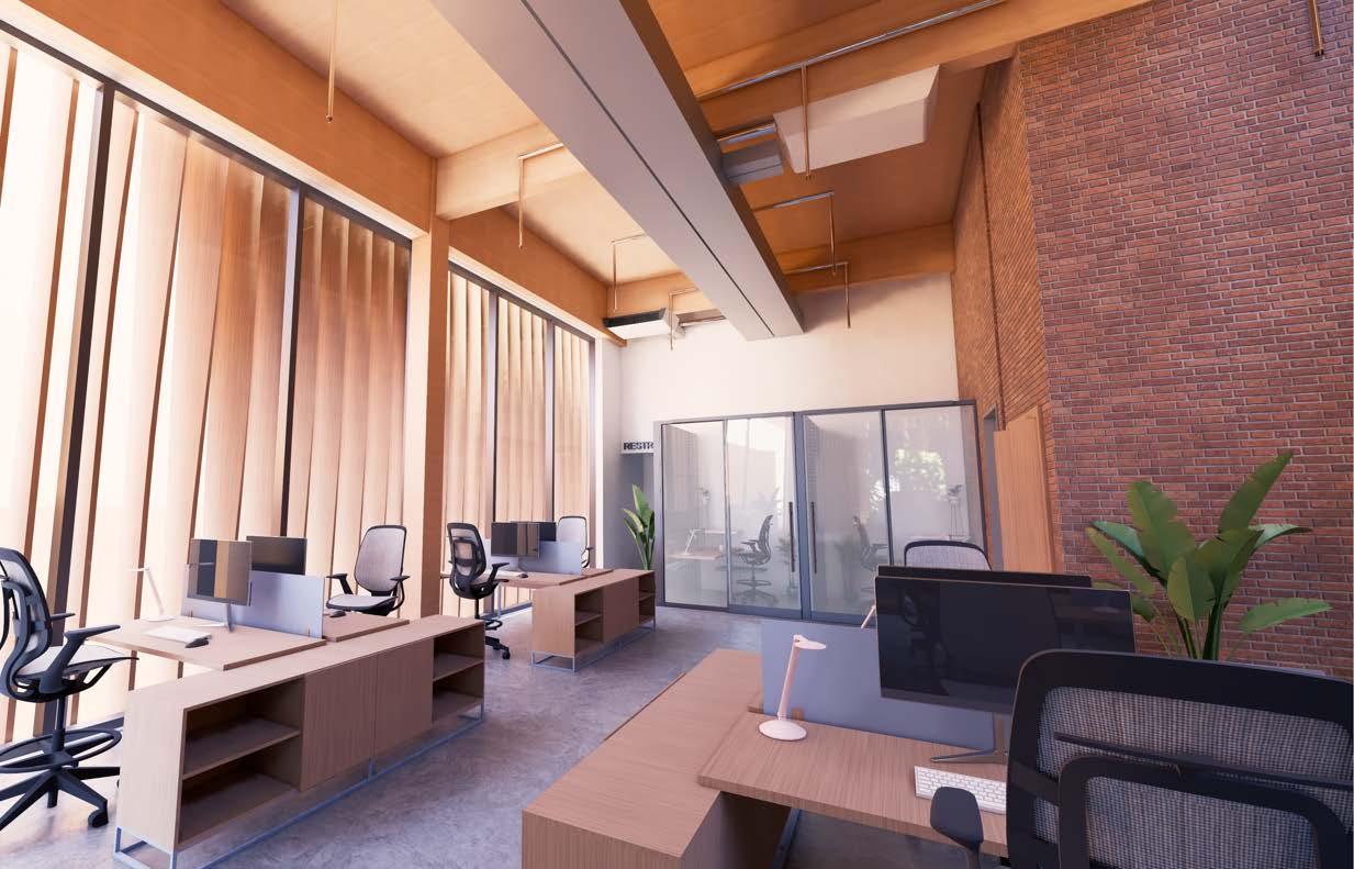
The third floor features a lot of private amenities so the space is not interrupted by users in the community. The screen acts as a privacy screen on this floor for the quiet lounge space and other parts of the program
Emily Thompson
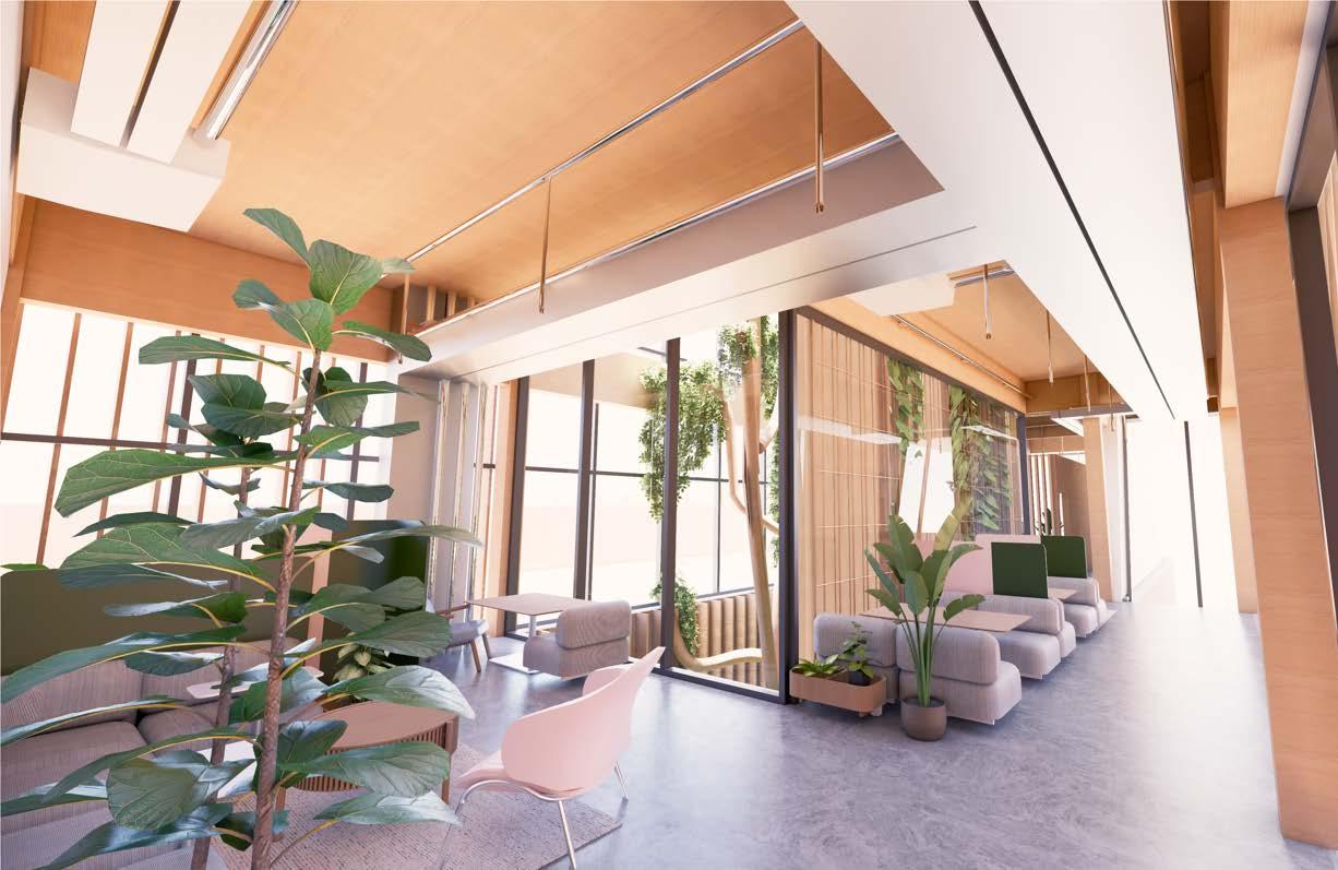
The design of the residential units encourages Emily to go and interact with other residents in the commons. The different amenities on this floor make her feel connected to the exterior environment and not constrained to her residential space.

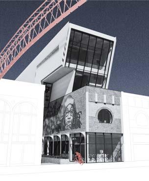
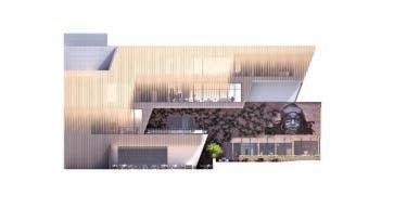
The Exterior facade conceptually is meant to absrat the existing brick and uses it as a "second skin" to express the different programs within the building layout.
The structure is conceptually made out of steel,with cantilevers to support the moments in the facade of the building that push out into the exterior space on the side of the building. Bay sizes are roughly 18x18 and existing structure would have to be replaced.
Design 5 | Team 05
Integrated Design 5 | Team 05


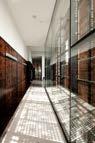
CORTEN STEEL MESH FACADE DETAIL
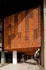
The Gabriela Mistral Cultural center uses a corten steel facade similar to this design. IT features a designed perforation that acts as a sunscreen for shading.
DETAIL
PERFORATED CORTEN STEEL PANEL
INSULATED GLASS UNIT
HORIZONTAL ALUMINIUM MULLION METAL FIXATION PIPE
This detail represents a way that we might be able to connect the perforated metal facade to a storefront condition. The design can changed to reflect the program. The current design is to reflect the existing brick pattern.
Integrated Design 5 | Team 05
Our team aims to gain a better understanding of the user scale architectural interventions that will affect the user base. Understanding the way immigrants and international students interact with this space will also be crucial in the design process when it comes to program
To gather this information we were involved in a series of Interviews with our desired constituents to gauge what they would invision in a cultural community center with transitional housing initiatives.
We also met with a group of constituents that had prior knowledge of Immigrants in the area due to their volenteer work
NIC CUSTER JOEL ARNOLD
Innovation Services Manager, UM-Flint
Board President, Buckham Gallery
Creative and Interactive Spaces:
Innovation Services Manager, UM-Flint
Board President, Buckham Gallery
-Integrate spaces for art and performance to encourage cultural exchange and community connection.
Insight: Art spaces foster cultural ties and can serve as a bridge for community bonding and expression.
-Partner with trusted local institutions, like churches and cultural centers, to enhance outreach and engagement.
Insight: Effective community spaces require collaboration with existing community organizations and neighborhood groups.
Residential Design for Families:
-Ensure that housing is family-friendly, with adequate space for immigrant families and diverse households.
Insight: Downtown housing should support varied family structures and provide access to communal areas.
LISA COUCH DAVID COUCH
Flint Local Volunteer Engages with International Students to at U of M Flint Bike Enthusiast
-We talked to Lisa and David Couch to gain more insights on immigrant transportation needs in a city, and how bike programs could serve as a solution. Lisa Couch does volunteer work with Spanish speaking students in Grand Rapids. In our interview she stated that, “for international students, having a bike gives them freedom because of how confusing they find public busing”. Her husband, David Couch, is a biking enthusiast and works with a bike donation organization where donated bikes are given or rented to those unable to afford one on their own.
-Integrating bike storage and repair is important since the existence of these amenities will support the difficulty of transportation for immigrant residents
- This type of program can be beneficial in Flint, for we found from Work 01 and Work 02 engagement that there is a large biking community in Flint due to various bike routes, including popular recreational routes that run along the Flint River. This means that there is a population in Flint that could provide biking equipment to those in need.
Integrated Design 5 | Team 05
“The extensive amounts of parking lots and gray infrastructure in downtown Flint limits the amount of green space and don’t promote green living”
-Cade Surface (Director of Urban Strategies at Crim Foundation)
“ Flint’s modern history is centered around short-sighted development and most often demolition of wellbuilt, walkable and dense urban structures in lue of cheap, ugly, and car-centric structures that continue to turn unique places into characterless, dime a dozen suburban-style development ”
- Nic Custer
“Integrate flexible spaces for things like art and performance that encourage cultural exchange and Foster community connection”
- Joel Arnold
“International students don’t know the context of Flint, so incubation and learning spaces would work well to help them adapt to a new environment.”
- Lisa Couch
design
Including green design practices and methods by integrating living spaces and sustainable materials.
preservation
Preserving existing structure and design to keep the buildings identity within the context of Flint.
spaces
Incluing spaces that can change progromatically depending on the user group and time of year.
interactive environments
Spaces for International residents and community memebers to network and foster connections to grow businesses and relationships in the city.
building
Programmatically including learning spaces and business icubation spaces that promote local entrprenuers and new residents to Flint.
Making the design of the building inclusive to allow all different types of people with different backgrounds to connect and interact in an equal space.
Integrated Design 5 | Team 05
Affordable and transitional housing, better public transportation, improved access to services, and community spaces that promote engagement between long term residents and immigrants.
Many issues facing circulation throughout flint is not the transportation offered, rather the distance to necessary facilities. There is not much walk ability except for spaces within the downtown area. Personal vehicles are a necessity for timely travel.
Demolition of existing buildings has led to an high amount of gray space within the city of flint. This high amount of gray space leaves much to be desired in usable park space for the Flint community to host events.
The existing building that our group will be designing for has historical elements that need to be considered when attempting to modernize the building.
If a new development were to be community focused and easily accessed, then engagement would increase, and more money would be circulated.
Access to events and increasing awareness of the events within flint seem to be a large concern for involving the current community. Cost of affordable housing will be important in maintaining inviting international students and immigrants.
What More information do we require?
We will want to understand the way transportation specifically affects international student and immigrant populations in the Flint area.
We will need to understand what types of spaces promote community interaction and how to make these accessble to residents in the Flint area. We will need to know how availible different learning spaces for skill devlopment for immigrant families that act as incubators for new business to support growth in the area.
How can we design residential spaces to cater toward immigrant populations and new residents in Flint in order to learn about the area.


TEAM 05 | INTEGRATED DESIGN 5
“ The extensive amounts of parking lots and gray infrastructure in downtown Flint limits the amount of green space and promotion of green living ”
Cade Surface (Director of Urban Strategies at Crim Foundation)
TEAM 05 | INTEGRATED DESIGN 5
“ Flint’s modern history is centered around short-sighted development and most often demolition of wellbuilt, walkable and dense urban structures ”
Nic Custer (Innovation Services Manager at U of M Flint)
TEAM 05 | INTEGRATED DESIGN 5
“ People don’t visit places because of parking. They visit because there’s something worth showing up for—a great restaurant, a unique shop, or a vibrant event. When your downtown is a draw, people will find a way to get there, parking or not. ”
Jeff Siegler (Author of Your City is Sick)
TEAM 05 | INTEGRATED DESIGN 5
TRANSITIONAL HOUSING
BUSINESS INCUBATION
“ A lot of
business assistance o ered by campuses in Flint are extremely hard to access if you are not a student ”
Nic Custer (Innovation Services Manager at U of M Flint)
“ Proven by the popularity of recently introduced Cuban and Venezualen restraunts, ethnic restraunts are a successful business in Flint ”
Nic Custer (Innovation Services Manager at U of M Flint)
TEAM 05 | INTEGRATED DESIGN 5
BUS ROUTES
BIKE ROUTES BUS STOPS
“ Having a bike is like freedom for students that struggle with english and understanding city bus routes ” Lisa Couch (Works with Spanish speaking students in Grand Rapids)
Biking Communities in Flint
• Friends of the Flint River Trail
• Genesee Wanderers Cycling Club
• Kentakee Athletic & Social Clubs
• Social Cycling Flint
Flint River Bike Trail
TEAM 05 | INTEGRATED DESIGN 5
Including biophilic design and sustainability practices
Preserving existing materials and design elements to keep the building’s identidy within the context of Flint
Spaces for residents and community members to network and foster connections to grow businesses and relationships in the city
Programmatically including learning spaces and business incubation spaces that promote educational development
Making the design of the building inclusive ot allow diverse people with different backgrounds to connect and interact in an equal space
“ The extensive amounts of parking lots and gray infrastructure in downtown Flint limits the amount of green space and promotion of green living ”
Cade Surface (Director of Urban Strategies at Crim Foundation)
“ Flint’s modern history is centered around short-sighted development and most often demolition of wellbuilt, walkbale and dense urban structures ”
Nic Custer (Innovation Services Manager at U of M Flint)
“ People don’t visit places because of parking. They visit because there’s something worth showing up for—a great restaurant, a unique shop, or a vibrant event. When your downtown is a draw, people will find a way to get there, parking or not. ”
Jeff Siegler (Author of Your City is Sick)
“ Spaces for things like art performance that encourage cultural exchange and foster community connection are needed in FLint ”
Joel Arnold (Planning and Advocacy Manager at Communities First)
“ A lot of business assistance o ered by campuses in Flint are extremely hard to access if you are not a student ”
Nic Custer (Innovation Services Manager at U of M Flint)
“ Proven by the popularity of recently introduced Cuban and Venezualen restraunts, ethnic restraunts are a successful business in Flint ”
Nic Custer (Innovation Services Manager at U of M Flint)
“ Having a bike is like freedom for students that struggle with english and understanding city bus routes ”
Lisa Couch (Works with Spanish speaking students in Grand Rapids)

The lack of dedicated community space and transitional housing leaves a need for the development of INTERACTIVE ENVIRONMENTS and housing strategies in Flint, Michigan. We envision an ADAPTIVE REUSE project that preserves the historic character of the building to ensure it remains integrated into the existing context. Programs will be introduced that promotes belonging, safety, collaboration, and a sense of community for new and existing residents through the inclusion of large, open, accessible gathering spaces and elements that reflect Flint’s cullture. The building will feature flexible spaces that can accommodate a variety of activities, from SKILL BUILDING to community driven events. Thoughtful implementation of design strategies will be utilized to create a space that balances private residential and public areas. These design strategies will address and support the needs of diverse populations, while also prioritizing INCLUSIVITY and public access. By integrating communal areas, such as shared kitchens, workspaces, and event rooms, the design aims to cultivate an environment where residents can connect, collaborate, and support one another. To promote mental health, environmental awareness, and positive social interaction, our building intends to incorporate strategies such as GREEN DESIGN approaches, including sunlight and biophilic design practices. With these factors in mind, the building will serve as a collaborative focal point and encourage a positive, interconnected community to stimulate Flint’s growth and expansion.
TEAM 05 | INTEGRATED DESIGN 5
TEAM 05 | INTEGRATED DESIGN 5

• Marcus’ days are spent managing his health, attending physical therapy appointments, and running errands with the help of a neighbor or public transportation.
• He enjoys sitting on his porch, chatting with neighbors, and tinkering with small projects in his home.
• Occasionally volunteers at his church by helping organize events, though his physical limitations make it hard to be as active as he’d like.
• Lives modestly on his Social Security benefits and a small pension.
• His home has narrow doorways and steep stairs, making it di cult for him to navigate without assistance.
• Relies on a walker and, on bad days, a wheelchair. The lack of ramps and grab bars in his home poses safety risks.
• Needs a ordable housing with wheelchair accessibility, including ramps, widened doorways, and a walk-in shower.
• Struggles to find transportation to medical appointments as Flint’s public transit system doesn’t always meet his needs.
Name: MARCUS THOMPSON
Age: 67
Hometown: Flint, MI
Occupation: Retired
Background: Marcus is a retired factory worker who spent over 30 years working for General Motors before the local plant closures. A lifelong Flint resident, he has seen the city’s ups and downs. He now lives alone in a small rental home but struggles with mobility issues due to arthritis and a recent hip replacement.
• Feels isolated at times, as his mobility challenges limit his ability to visit friends or participate in community activities.
• Friendly and down-to-earth, Harold is known for his storytelling and his sense of humor.
• Resilient despite his challenges, he remains hopeful about finding a better living arrangement that will allow him to maintain his independence.
• Deeply connected to his community, Marcus dreams of staying in Flint but with improved accommodations that support his aging needs.
• Marcus is working with local housing advocates to apply for a ordable, accessible senior housing.
• He hopes to secure an apartment in a complex that o ers community events for seniors.
• Wants to stay engaged with his church and possibly start a support group for older adultswith mobility issues
• Ayesha juggles her classes, research projects, and part-time work as a teaching assistant in the Public Health department.
• She’s also actively involved in the International Students Organization, organizing cultural exchange events to foster a sense of belonging among students from diverse backgrounds, and has interest in joining the e orts of ICGF.
• On weekends, she volunteers at a local nonprofit working on water quality and public health awareness in Flint.
• Lives in a shared apartment near campus with two roommates—one from China and another from Brazil.
• Cooks Pakistani dishes to stay connected to her roots, often sharing meals with her roommates to introduce them to her culture.
• Spends her free time exploring local co ee shops, parks, reading novels, or calling family back home.
• Adjusting to the cultural di erences in everyday life.
• Faces financial strain from tuition fees and living expenses, leading her to carefully budget her resources.
• Navigates the emotional challenges of being far from her family and support network.
Name: AYESHA KHAN
Age: 22
Hometown: Lahore, Pakistan
Occupation: Master’s student in Public Health at the University of Michigan-Flint
Background: Ayesha grew up in Lahore, where she developed a strong interest in addressing health inequities after volunteering at local clinics during high school. Motivated by her passion, she applied for graduate programs in the United States and chose the University of Michigan-Flint for its focus on community health and proximity to underserved populations.
• Warm, empathetic, and curious, Ayesha is always eager to learn from the diverse perspectives of her peers.
• She loves nature and is passionate about sustainability and the ways pollution impacts health
• Known for her strong organizational skills and ability to bring people together, she is a natural leader in her student groups.
• Despite occasional homesickness, Ayesha remains determined to make a di erence in Flint and apply her knowledge to improve health systems in Pakistan after graduation.
• She desires a unique space to host cultural exchange events that feels welcoming and equitable.
• Would appreciate more green space and parks where she can enjoy a peaceful environment to read novels or work on classwork.
• To use her leadership skills in involvement with the International Center of Greater Flint
• Omar works full-time as a server in Downtown Flint, and is grateful for steady employment.
• In the evenings, he attends night classes at a community college, studying business management with the dream of opening a Middle Eastern grocery store in Flint.
• On weekends, he volunteers at a local mosque, helping other refugees navigate life in the U.S.
• Lives in a modest three-bedroom house with multiple roommates, with hopes of building an income that can support a place for his family.
• Enjoys cooking traditional Syrian dishes and exploring the small but growing international food scene in Flint.
• Stays connected to his homeland through news updates and WhatsApp calls with relatives still in Syria.
• Feels completely disconnected from the local communities in Flint.
• Often gets irritated with roommates and needs a private space to focus on classwork after a long day of work.
• His work schedule often conflicts with when the Flint Farmer’s Market’s incubator kitchen is open limiting his opportunies to use commercial kitchen equipment.
Name: OMAR ALI
Age: 31
Hometown: Aleppo, Syria
Occupation: Restraunt server and aspiring entrepreneur
Background: Omar fled Syria in 2015 due to the civil war, spending three years in a refugee camp in Turkey before being resettled in Flint through a refugee resettlement program. With limited English upon arrival, he worked hard to learn the language while supporting his wife and son still in Syria.
Flint’s close-knit immigrant community as well as job and educational opportunities has helped him start rebuilding his life.
• Finds it di cult to balance the financial pressures of supporting his family while pursuing his entrepreneurial dreams.
• Struggles with the commute to work without a Driver’s license and personal vehicle.
• Resilient and determined, Omar is deeply committed to creating a better future for his family.
• Friendly and community-oriented, he has become a mentor to newly arrived refugees, o ering them guidance and encouragement.
• Grateful for the opportunities he’s found in Flint, he views his challenges as stepping stones toward achieving his long-term goals.
• Hopes to use business and food knowledge to open a Middle Eastern grocery store in Flint
• Wants to move out of his current house into a space that provides private spaces for him to focus on developing his skills
• Works hard to provide for his wife and son with the goal of eventually bringing them into the US.
TEAM 05 | INTEGRATED DESIGN 5
TEAM 05 | INTEGRATED DESIGN 5
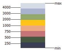
ALLOWED BUILDING HEIGHT
Zoning: 125’
Code (Type IV Building) 85’
ALLOWED # of FLOORS
4 floors above grade (2 additional from existing)
1 floor below grade
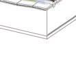
Side lot condition o ers the opportunity for development to support this site, as well as the neighboring Cork restaurant
TEAM 05 | INTEGRATED DESIGN 5
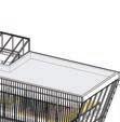
Building form is expanded upward as well as into the side lot condition. Scale of the portion along Saginaw Street is retained to remain harmonious with neighboring building forms.
TEAM 05 | INTEGRATED DESIGN 5
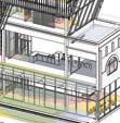
Expansion is angled relative to equinox sun and site positioning to integrate daylighting during winter months and less during summer months.
20.21°
Expansion is carved to allow for balcony conditions and to further the relationship between the existing envelope and the expanded form.
Building is cored to integrate green design strategies like daylighting and planting elements.
TEAM 05 | INTEGRATED DESIGN 5
Side lot condition is split between the Saginaw Street elevation and the lower alley elevation behind, allowing for multiple program elements to coexist in this space.
Facade element is appled to exposed side of expanded building form.
Facade element is twisted to expose interior space and allow for perforation into the building envelope.
Facade element is lifted to cover the lower side condition and further develop this as a seperate space from that along the Saginaw Street frontage.
TEAM 05 | INTEGRATED DESIGN 5
From Work 3, Iteration 1 design considerations that were carried into Work 4 include carved out balcony spaces, side lot spatial seperation, and program elements like bike repair.
TEAM 05 | INTEGRATED DESIGN 5
From Work 3, Iteration 2 design considerations that were carried into Work 4 include an applied facade element with integrated louvers and daylight strategies.
TEAM 05 | INTEGRATED DESIGN 5
From Work 3, Iteration 3 design considerations that were carried into Work 4 include biophilic design elements centered in the building core, a raised side lot condition to Saginaw Street grade, and the retained original frontage.
Circulation
- Vertical Circulation: Elevator
- Vertical Circulation: Egress Stairs
- Vertical Circulation: Utility Lift
- Circulation: Exterior Entrance
- Circulation: Lobby
- Circulation: Open Lounge Space
- Circulation: Private + Immediate Egress
- Circulation: Utility Access
Green Implementation
- Green Core
- Lightwell
Other
- Single Occupant Restroom
- Single Occupant Restroom + Shower
- Garage
- Storage
- Mechincal/HVAC
Public
- Event Space
- Event Space: Exterior
- Shared Exterior Seating with Cork
- Bike Rental + Storage
- Incubator Kitchen
Office Space
- Open Office Space
- Office Kitchen
- Office Lounge Space
- Office Balcony
- Meeting Room
- Private Office Space
Housing + Ammeneties
- Transitional Housing Units
- Housing Lounge
- Shared Kitchen
- Balcony
- Workout Room
- Laundry
- TEAM 05 | INTEGRATED DESIGN 5
TEAM 05 | INTEGRATED DESIGN 5
Marcus Thompson, 67
Hometown: Flint, MI
Retired
Ayesha Khan, 22
Hometown: Lahore, Pakistan
Master’s student in Public Health at UofM Flint
Omar Ali, 31
Hometown: Aleppo, Syria
Restraunt server and aspiring entrepreneur
- TEAM 05 | INTEGRATED DESIGN 5
TEAM 05 | INTEGRATED DESIGN 5

TEAM 05 | INTEGRATED DESIGN 5

TEAM 05 | INTEGRATED DESIGN 5


TEAM 05 | INTEGRATED DESIGN 5


TEAM 05 | INTEGRATED DESIGN 5

TEAM 05 | INTEGRATED DESIGN 5


TEAM 05 | INTEGRATED DESIGN 5

TEAM 05 | INTEGRATED DESIGN 5

TEAM 05 | INTEGRATED DESIGN 5
TEAM 05 | INTEGRATED DESIGN 5
Primary: 12” x 12” Columns
Secondary: 36” deep Girders
Tertiary: 27” deep Beams


To integrate the incubator kitchen into the environmentally conscious design intent, a commercial composter can be used. The machine would include a waste grinder, a wood pellet feeder, and fan aeration system to ensure waste is processed quickly and e ciently. The end product is a dry, high nutrient compost which the plants can use throughout the building. All biodegradeable waste from the kitchen or even the housing units can be used. It has a processing capacity of approximately 1400 litres of food waste per week, with a turnaround of 4 weeks from food waste to garden compost.
Commercial rainwater collection systems e ciently collect large amounts of rainwater from both roofs and storm overflows. This allows the building to repurpose that water into a variety of applications including: stormwater management, fire suppression, irrigation, fixture flushing, cooling towers, and laundry. Rainwater harvesting can help buildings conserve millions of gallons of water over the lifetime of their system, making the building more sustainable and self-su cient, while also saving money.
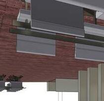
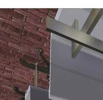
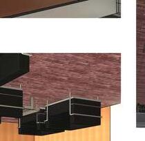
Concrete Topper Rigid Insulation 5-ply CLT
Aluminum Paneling Air / Water Barrier
SIP Panel
Aluminum Paneling
Gravel Layer
Roofing Membrane
Plywood Membrane
Concrete Topper
Rigid Insulation
5-ply CLT
to CLT slabs
Aluminum Paneling
Rigid Insulation
Air / Water Barrier
Plywood Membrane
Metal Stud Vertical Plywood Fins
Exterior Veneer Brick Air / Water Barrier SIP Panel Interior Veneer Brick
Custom Concrete Coping for Skylight Connection
Aluminum Paneling Air / Water Barrier
Plywood Membrane
Rigid Insulation Mass Timber Framing
Cast-in-Place Concrete
Metal Stud w/
Rigid Insulation
Plywood Membrane CMU
Planter Box Membrane
Cast-in-Place Concrete
Metal Stud w/
Rigid Insulation
Plywood Membrane
CMU
Plywood Membrane
Air / Water Barrier
Exterior Veneer Brick
Angled Skylight allows for water to run o into the Planter Box, eliminating pooling
Planter Box Membrane CMU
Plywood Membrane
Exterior Veneer Brick


TEAM 05 | INTEGRATED DESIGN 5

TEAM 05 | INTEGRATED DESIGN 5


TEAM 05 | INTEGRATED DESIGN 5

TEAM 05 | INTEGRATED DESIGN 5

EX TER I OR LO UVER SYSTE M


TEAM 05 | INTEGRATED DESIGN 5
TEAM 05 | INTEGRATED DESIGN 5
TEAM 05 | INTEGRATED DESIGN 5

TEAM 05 | INTEGRATED DESIGN 5
TEAM 05 | INTEGRATED DESIGN 5
TEAM 05 | INTEGRATED DESIGN 5


- 1"
2 12' - 6"
Level 1 0' - 0"
Load Calculations of Typical bay of Colonnade
DL = 15 psf
LLr = 20 psf
LLf = 50 psf
Note: Roof of colonnade is occupiable, use floor live loads.
Beam BA
Tributary area = 1/2(10 x 5) = 25 sqft
DL + LLf = 15 + 50 = 65 psf
B1 Loading: 65(25) = 1625 #
Because of symmetry, R1a = R2a.
So R1a + R2a = 1625 #
R1a = R2a = 1625/2 =812.5 #
By similarity, loading and reactions on BC are the same as BA.
Beam BB
Tributary area = 2 x [1/2(10 x 5)] = 50 sqft
DL + LLf = 15 + 50 = 65 psf
B1 Loading: 65(50) = 3250 #
Because of symmetry, R1b = R2b.
So R1b + R2b = 3250 #
R1b = R2b = 3250/2 = 1625 #
By similarity, loading and reactions on BD are the same as BB.
Column loadings
C1 = R1a + R1d = 812.5 + 1625 = 2437.5 #
By similarity, C1 = C2 = C3 = C3 = 2437.5 #
RETENTION WALL AROUND THE EXISTING TREE
AREA HAS RAISED LANDSCAPE OPEN SKY COURTYARD IN THE CENTER
STOREFRONT CANOPY AT THE FRONT ENTRANCE
THERE IS NO BASEMENT IN THE FRONT HALF OF BUILDING. BOTTOM OF FTGS. TO BE 48" BELOW GRADE
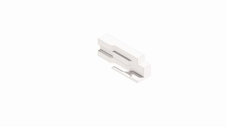
c/01/ 3D Ext./ "SE" Abv./ Design Mass Model/ (A001 x256)
GENERAL NOTES
1. MASS MODEL IS USED TO VERIFY THAT UN1-7 CONSTRUCTION SYSTEMS ARE CORRECTLY MATCHING PRECEDENT BLDG. DESIGN
LINE OF "PLACEHOLDER" OBJECT (TO BE DEVELOPED). AREA TO COORD.; AREA/ITEM REVISED (RED, THEN BLACK).
DOUBLE HEIGHT WING ON FRONT
CANOPIES ARE CANTILEVERED
LANDSCAPED COURTYARDS
WING WALL IS USED TO HIDE EXTERIOR MECHANICAL EQUIPMENT
THERE IS A BASEMENT ON REAR END OF STRUCTURE. BOTTOM OF STRIP FTGS. 13'-6" BELOW GRADE
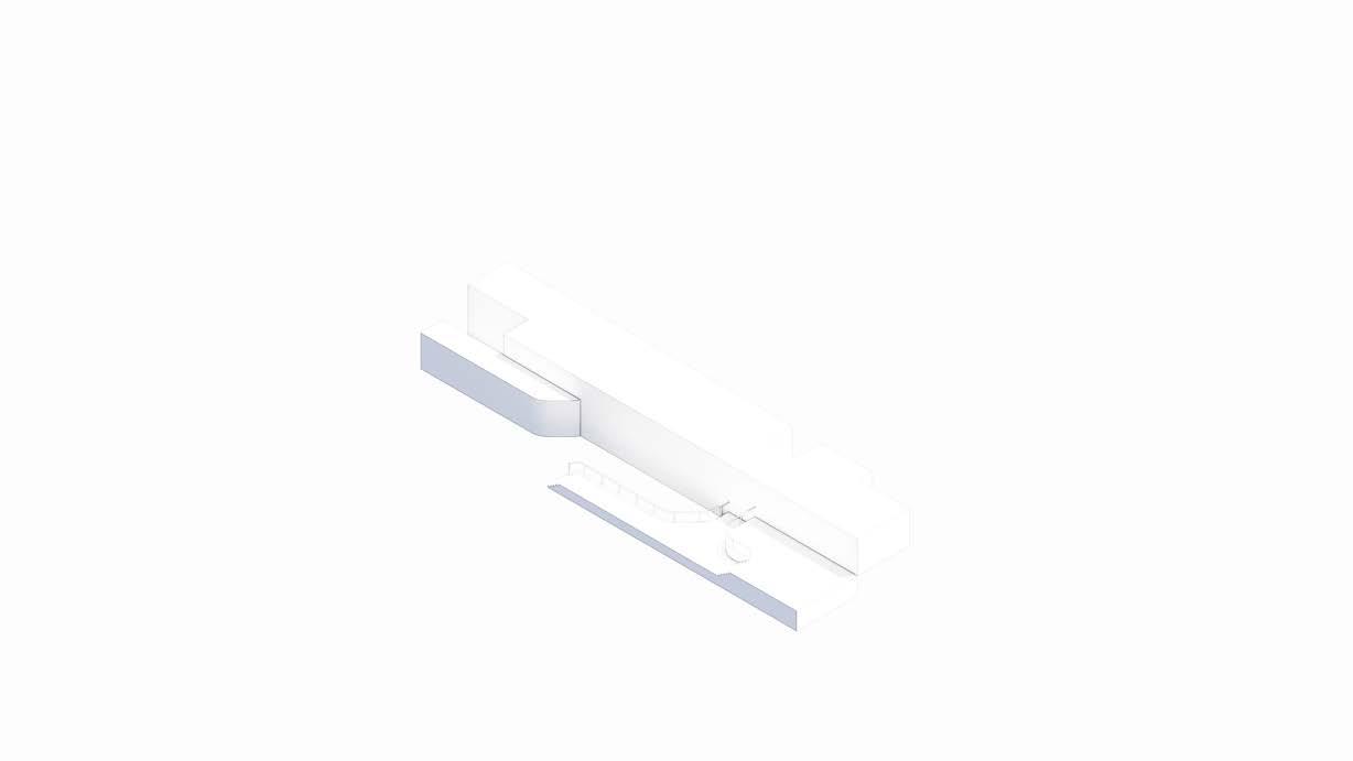
c/02/ 3D Ext./ "NW" Abv./ Design Mass
RETAINING WALL FOR EXCAVATION
GENERAL NOTES
1. MASS MODEL IS USED TO VERIFY THAT UN1-7 CONSTRUCTION SYSTEMS ARE CORRECTLY MATCHING PRECEDENT BLDG. DESIGN
LINE OF "PLACEHOLDER" OBJECT (TO BE DEVELOPED).
AREA TO COORD.; AREA/ITEM REVISED (RED, THEN BLACK).
RETENTION WALL FOR EXCAVATION.
DEPTH TO BE NOT LESS THAN TWICE EXCAVATION DEPTH. DO NOT REMOVE.
COORD. SLAB
DEPRESSED 2" TO ALLOW FOR FINISH FLOOR, & HELD BACK 4" TO ALLOW FOR STRUCT. BEARING
SLAB ON GRADE AT L1 ISOLATED COLUMNS TO SIT BELOW SLAB ON GRADE (TYP.)
PARTIALLY UNEXCAVATED AREA WITH COMPACTED
FILL UP TO SLAB ON GRADE
STRIP FTG. BELOW WALL (TYP.)
COLUMN FTG BELOW COL. (TYP.) TO EXTEND 1' BELOW STRIP FTG.
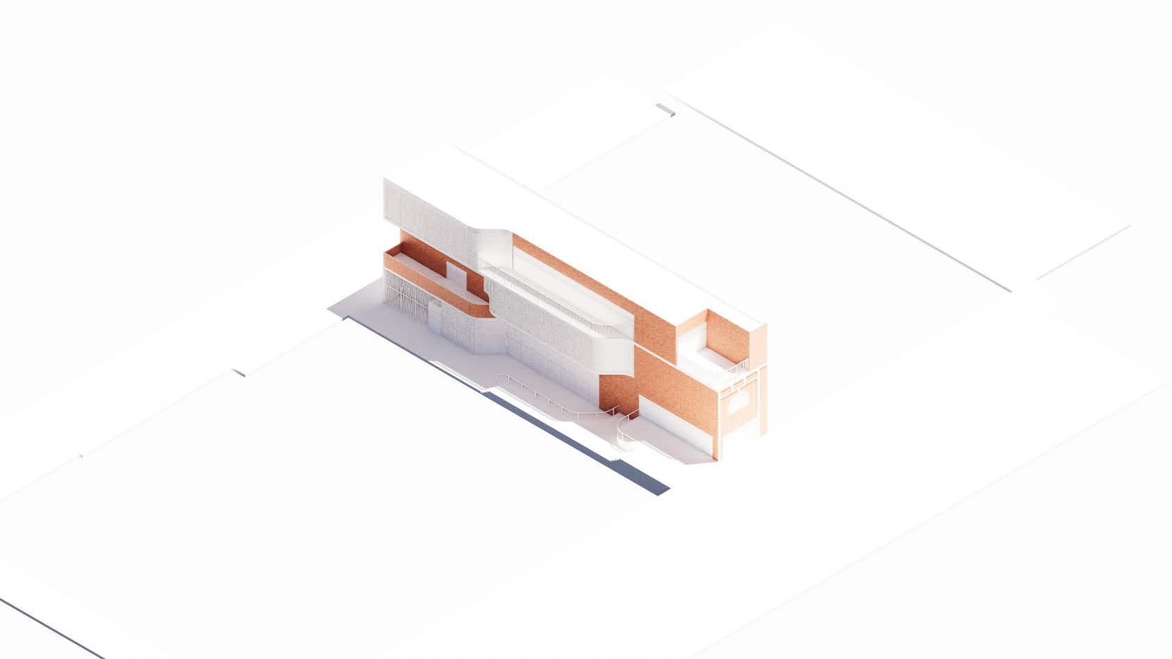
c/12/ 3D Ext./ "SE" Abv./ Foundation/ (A012 x256)
CONFIGURATION & DEPTHS OF EXCAVATION IS DETERMINED BY VARYING DEPTHS OF FOOTINGS
LINE OF EXCAVATION CUT
WATERPROOFING & DRAINAGE MAT AT L0 BASEMENT PERIMETER
FOUNDATION WALL (TYP.)
STRIP FTG. BELOW WALL (TYP.)
EDGE OF ROAD
FOUNDATION DRAIN AT L0 BASEMENT PERIMETER
ENGAGED COLUMN (TYP.)
SLEEVE TO BE PROVIDED WHERE FOUNDATION DRAIN PIPE PENETRATES WALL
COLUMN FTG. BELOW COL. (TYP.)
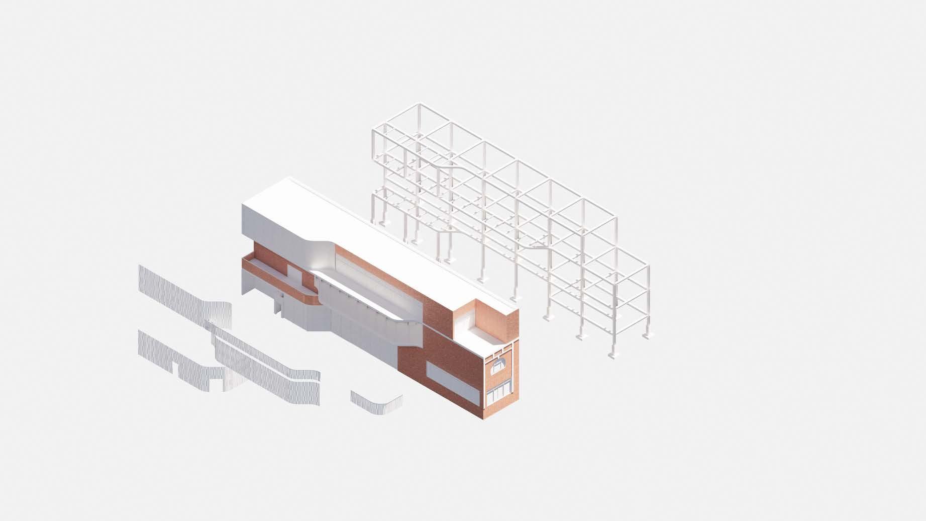
LINE OF "PLACEHOLDER" OBJECT (TO BE DEVELOPED). AREA TO COORD.; AREA/ITEM REVISED (RED, THEN BLACK).
COLUMN HELD BELOW BEAM AT STRUCTURAL WING FOR STABILITY
FRAMED OPENING IN FLOOR FOR ELEVATOR (ELEVATOR TO BE DEVELOPED)
LATERAL BRACING: SHEAR DIAPHRAGM IN BAY OF STR. FRAME; INTEGRATE WITH SPECIFIC WALL CONSTRUCTION TYPE
W 10X49 COLS. (TYP.)
HSS STL. GIRT FOR EXT. WALL SUPPORT
MTL. ROOF DECKING ON MTL. JOISTS ON MTL. BMS. (TYP.)
DIFFERENT LAYERS OF BEAMS AND FRAMING STACKED WHERE DIFFERENT SYSTEMS INTERSECT; REFER TO GENERAL NOTES FOR INTENT
12XS PIPE COLS. AT FRONT ENTRY
HSS 8X8 COLS. (TYP.)
c/13/ 3D Ext./ "SE" Abv./ Structure Horiz. & Vert./ (A013 x256)
FRAMED OPENING IN FLOOR FOR ELEV. (ELEV. TO BE DEVELOPED LATER)
8" x 6" x 1/2" HSS GIRTS FOR LATERAL BRACING (TYP.)
CONC. FOUNDATION WALL WITH ENGAGED COLS. (TYP.)
3" CONC. ON 2" CORRUGATED MTL. DECKING
WIDE FLANGE W 21X62 BEAMS DISCONTINUOUS BETW. WIDE FLANGE AND HSS COLS. (TYP.)
CANTILEVERED CORRUGATED MTL. DECKING BLADE CANOPY (TYP.)
HSS STL. 8" x 8" x 1/2" COLS. CONTINUOUS TO ROOF DECK (TYP.); REFER TO SHEETS S120 AND S121 FOR EXCEPTIONS
CANTILEVERED BEAM AT CORNER
CORRUGATED MTL. DECKING CANOPY AT ENTRANCE
LINE OF "PLACEHOLDER" OBJECT (TO BE DEVELOPED). AREA TO COORD.; AREA/ITEM REVISED (RED, THEN BLACK).
COLUMN HELD BELOW BEAM AT STRUCTURAL WING TO PROVIDE STABILITY
VERTICAL ELEV. SHAFT HELD 2' BELOW DECK TO ALLOW FOR JOIST HEIGHT
LATERAL BRACING: SHEAR DIAPHRAGM IN BAY OF STR. FRAME; INTEGRATE WITH SPECIFIC WALL CONSTRUCTION TYPE
W 10X49 COLS. (TYP.)
HSS STL. GIRT FOR EXT. WALL SUPPORT
6" METAL STUD SUBSTRATE WALL ABOVE GIRT TO TOP OF PARAPET (TYP.)
2" RIGID INSUL. CONTINUOUS ACCROSS SUBSTRATE (TYP.)
8" CMU SUBSTRATE WALL UP TO UNDERSIDE OF STRUCT. GIRT (TYP.)
MTL. ROOF DECKING ON MTL. JOISTS ON MTL. BMS. (TYP.)
3' OPENING ABOVE GIRT AT VESTIBULE ENTRY
DIFFERENT LAYERS OF BEAMS AND FRAMING STACKED WHERE DIFFERENT SYSTEMS INTERSECT; REFER TO GENERAL NOTES FOR INTENT
MTL. STUD SUBSTRATE HELD BACK FROM STRUCTURE TO ALLOW FOR FUTURE GLAZING
CMU KNEE WALL AT FRONT OF BUILDING TO SUPPORT STOREFRONT GLAZING
c/14/ 3D Ext./ "SE" Abv./ Walls Substate & Interior/ (A014 x256)
OF "PLACEHOLDER" OBJECT (TO BE DEVELOPED).
TO COORD.; AREA/ITEM REVISED (RED, THEN BLACK).
8" CMU SUBSTRATE WALL AT WING WALL & AT MIRRORED SIDE
METAL ROOF EDGE AND FASCIA AT METAL ROOFING
4" CMU SUBSTRATE WALL AT WING EXTENSIONS
METAL ROOFING SYS. ON ROOFING INSUL. SYS. (AT INT. AREAS ONLY)
REFER TO STRUC. DWGS. FOR STRUC. SIZES AND TYPES (TYP.)
METAL FURRING BELOW/AROUND WINDOW OPENING (TYP.)
FRAMED WINDOW OPENING (TYP.)
8" CMU SUBSTRATE WALL UP TO UNDERSIDE OF STRUCTURE ABOVE
2" CONTINUOUS INSULATION ALONG EXTERIOR WALLS
c/16/ 3D Ext./ "SE" Abv./ Exterior Enclosure/ (A016 x256)
2" EXTRUDED ALUM. COPING ON TOP OF ASHLAR FACADE
2" MTL. PNLS. ABOVE COURTYARD CURTAINWALLS
GENERAL NOTES
1. REFER TO MATLS. NARR. FOR ADDNL. INFO. ON TYP. CONDITIONS.
2. REFER TO DETAILS & OTHER DWGS. FOR MATL'S NOT NOTED.
3. WD. CALD. SYS.: 1 1/2" THK. HORIZ. WD. BATTENS (2" O.C. WITH 1/2" HORIZ. GAPS)
4. MTL. PNL. CLAD. SYS.: 1" MTL. PNL. OPEN-JT. SYS.
5. FLASH. SYS.: SHT. MTL. FLASHING WITH DRIP, OVER SUBSTRATE AS NOTED.
6. WD. WINDOW & DOOR SYS.: CLAD WD. FRAME, FIXED & OPERABLE SASH & DOORS, INSUL. GLASS.
7. ALUM. WINDOW & DOOR SYS: PRE-FIN. ALUM. SUBFRAMES, OPERABLE SASH & DOORS, INSUL. GLASS.
8. ALUM. CURTAINWALL SYSTEM: PRE-FIN. ALUM. FRAMING, INSUL. GLASS.
CONC. FND. WALL AND FTG. ASSY. BELOW (TYP.)
LINE OF STEPPED FTGS. 2H : 1V (TYP. )
9. EAVE. ASS'Y.: IX TRIM BD. FASCIA PTD., 1/2" SOFFIT PANELS PTD.
10. MEMB. ROOFING SYS.: FULLY ADHERED MEMBRANE ROOFING.
11. MTL. ROOFING SYS.: 3" DP. GLAV. CORRUG. MTL. PANELS, W. END & SIDE CLOSURES.
12. ROOFING TERMINATION SYS.: SHT. MTL. COUNTERFLASHING & EDGE TRIM.
BRICK VENEER KNEE WALL BELOW STOREFRONT CURTAIN WALL
13. ROOFING DRAINAGE SYS.: PRE-FIN. ALUM. GUTTER WITH BRACKETS (24" O.C.)
MODEL/VIEW DEVLPMT. LEGND.
LINE OF "PLACEHOLDER" OBJECT (TO BE DEVELOPED).
AREA TO COORD.; AREA/ITEM REVISED (RED, THEN BLACK).
METAL ROOF EDGE AND FASCIA AT METAL ROOFING
8" CMU SUBSTRATE WALL AT WING WALL & AT MIRRORED SIDE
FLOOR ASSEMBLYREFER TO STRUCTURAL DRAWINGS (TYP.)
REFER TO STRUC. DWGS. FOR STRUC. SIZES AND TYPES (TYP.)
2" CONTINUOUS INSULATION ALONG EXTERIOR WALLS FRAMED WINDOW OPENING (TYP.) METAL FURRING BELOW/AROUND WINDOW OPENING (TYP.)
c/17/ 3D Ext./ "NW" Abv./ Exterior
Enclosure/ (A017 x256)
2" SMALL ASHLAR STONE VENEER AT FRONT FACADE
BLADE CANOPY W/ BUILT UP CUSTOM CORNICE AT FRONT ENTRANCE
GENERAL NOTES
1. REFER TO MATLS. NARR. FOR ADDNL. INFO. ON TYP. CONDITIONS.
2. REFER TO DETAILS & OTHER DWGS. FOR MATL'S NOT NOTED.
3. WD. CALD. SYS.: 1 1/2" THK. HORIZ. WD. BATTENS (2" O.C. WITH 1/2" HORIZ. GAPS)
4. MTL. PNL. CLAD. SYS.: 1" MTL. PNL. OPEN-JT. SYS.
CORNICE AT PARAPET. SEE AXON FOR LOCATIONS
WD. SLAT CLADDING ON 6" MTL STUD
5. FLASH. SYS.: SHT. MTL. FLASHING WITH DRIP, OVER SUBSTRATE AS NOTED.
6. WD. WINDOW & DOOR SYS.: CLAD WD. FRAME, FIXED & OPERABLE SASH & DOORS, INSUL. GLASS.
7. ALUM. WINDOW & DOOR SYS: PRE-FIN. ALUM. SUBFRAMES, OPERABLE SASH & DOORS, INSUL. GLASS.
8. ALUM. CURTAINWALL SYSTEM: PRE-FIN. ALUM. FRAMING, INSUL. GLASS.
9. EAVE. ASS'Y.: IX TRIM BD. FASCIA PTD., 1/2" SOFFIT PANELS PTD.
10. MEMB. ROOFING SYS.: FULLY ADHERED MEMBRANE ROOFING.
11. MTL. ROOFING SYS.: 3" DP. GLAV. CORRUG. MTL. PANELS, W. END & SIDE CLOSURES.
12. ROOFING TERMINATION SYS.: SHT. MTL. COUNTERFLASHING & EDGE TRIM.
13. ROOFING DRAINAGE SYS.: PRE-FIN. ALUM. GUTTER WITH BRACKETS (24" O.C.)
LINE OF RETAINING WALL
MODEL/VIEW DEVLPMT. LEGND.
LINE OF "PLACEHOLDER" OBJECT (TO BE DEVELOPED).
AREA TO COORD.; AREA/ITEM REVISED (RED, THEN BLACK).
GYPSUM WALL BOARD INTERIOR WALL (TYP.)
PENDANT LIGHTING FIXTURE
HVAC DUCTS (TYP.)
STRUCTURAL COLUMNS WRAPPED IN GWB WALLS
TALL SHELVING (TYP.)
c/18/ 3D Int./ Cam. to "E"/ Interior Space/ (A018 xNTS)
GYPSUM WALL BOARD CEILING (TYP.)
GLAZING SYSTEM ABOVE
WOOD TRIM ABOVE GLAZING SYSTEM
EXTERIOR WOOD SLATS UNDER BLADE CANOPY
GLAZING SYSTEM IN READING ROOM PERIMETER
BUILT-IN SHELVING BELOW GLAZING SYSTEM (NOT SHOWN IN RENDERING)
INTERIOR WOOD FLOORING IN READING ROOM
LINE OF "PLACEHOLDER" OBJECT (TO BE DEVELOPED). AREA TO COORD.; AREA/ITEM REVISED (RED, THEN BLACK).
LINE OF FOUNDATION DRAIN AT BASEMENT PERIMETER
LINE OF EXCAVATION CUT (FOR REFERENCE)
CONFIGURATION & DEPTH OF EXCAVATION IS DETERMINED BY VARYING DEPTH OF FOOTINGS
LINE OF STEP IN FOOTING (TYP.)
4" THK EARTH RETENTION SYSTEM
LINE OF EXTERIOR WALL FACE
PARTIALLY UNEXCAVATED AREA, WITH COMPACTED FILL UP TO SLAB ON GRADE
PROPERTY LINE (TYP.)
COLUMN FTG. BELOW COL. (TYP.)
ENGAGED COLUMN (TYP.)
STRIP FTG. BELOW WALL (TYP.)
FOUNDATION WALL (TYP.)
1. REFER TO MATERIALS NARRATIVE FOR ADDITIONAL INFORMATION ON TYPICAL CONDITIONS.
2. GENERAL NOTES ARE TYPICAL (TYP.) UNLESS NOTED OTHERWISE (U.N.O.).
3. FOUNDATION WALLS: REINF. CONC. 12" THK.
4. STRIP FOOTINGS: REINF. CONC. 24" W. X 12" D.
5. ENGAGED COLUMNS (PIERS): REINF. CONC. 14" X 14".
6. COLUMN FOOTINGS: REINF. CONC. 48" X 48" X 24" D.
7. SLAB ON GRADE: 5" REINF. CONC. WITH 8" THICKENED EDGES, ON VAPOR RETARDER, ON 6" MIN. COMPACTED SAND.
8. SLABS TO HAVE CONTRAL JOINTS AS SHOWN, & COMPRESSIBLE FILLER WHERE ABUTTING OTHER STRUCT. ELEMENTS.
9. ROUND DRILLED-PIER FOOTINGS (AS APPLICABLE): REINF. CONC. 12" DIA.
STEPPED FTG. (TYP.)
10. RETAINING WALLS (AS APPLICABLE): REINF. CONC. 16" THK., WITH ASYMMETRIC FOOTING, REFER TO STRUCT. DWGS.
11. BOTT. OF FOOTINGS TO BE 42" MIN. BELOW GRADE (LOCAL FROST DEPTH).
12. FROST BLOCK (AS APPLICABLE): MASS CONC. DOWN TO BOTTOM OF FOOTINGS.
FRAMED OPENING IN FLR. FOR STAIR (STAIR TO BE DEVELOPED)
FRAMED OPENING IN FLR. FOR ELEVATOR (ELEVATOR TO BE DEVELOPED)
SLAB ON GRADE AT L0 BASEMENT
W 16X40 BEAMS (TYP.)
W 21X62 GIRDERS (TYP.)
4" THK EARTH RETENTION SYSTEM
LATERAL BRACING: SHEAR DIAPHRAGM
LATERAL BRACING: X-BRACING IN BAY OF STR. FRAME; INTEGRATE WITH SPECIFIC WALL CONSTRUCTION
COORD. SLAB DEPRESSED 2" TO ALLOW FOR FINISH FLOOR, & HELD BACK 4" TO ALLOW FOR STRUCT. BEARING
HSS 8X8 COLS. (TYP.)
LINE OF EXT. GLAZING & WALL CLADDING TO BE DEVELOPED (TYP.)
LINE OF EXTERIOR WALL FACE SLAB ON GRADE AT L1, WITH THICKENED EDGES
PARTIALLY UNEXCAVATED AREA, WITH COMPACTED FILL UP TO SLAB ON GRADE
W 10X49 COLS. (TYP.)
LINE OF GARDEN TERRACE (TO BE DEVELOPED)
PROPERTY LINE (TYP.)
1. REFER TO SHT. S100 FOR CONCRETE & FOUNDATION GENERAL NOTES. 2. REFER TO MATERIAL NARRATIVE FOR ADDITIONAL INFORMATION ON TYP. CONDITIONS.
3. COLUMNS/POSTS: SIZE & WOOD/STEEL/CFMF AS INDICATED. BASE PLATE AT FOUNDATION. CONNECTION TYPES (AT BEAMS/HEADERS) AS INDICATED. (TYP.)
4. BEAMS/HEADERS: SIZE & WOOD/STEEL/CFMF AS INDICATED
PRIMARY/SECONDARY/OTHER AS INDICATED. CONNECTION TYPES (AT COLS./POSTS) AS INDICATED. (TYP.)
5. LATERAL BRACING: OF TYPE INDICATED. (TYP.)
6. JOISTS/TRUSSES (FLOOR/ROOF): SIZE & WOOD/STEEL/CFMF AS INDICATED (TYP.)
7. DECKING (FLOOR/ROOF): WOOD/STEEL AS INDICATED, WITH SPAN AS INDICATED. (TYP.)
8. CONC. SLAB: THICKNESS & REINF. AS INDICATED (IF PRESENT). (TYP.)
STRUCTURAL FRAMING LEGEND
PRIMARY, SECONDARY, TERTIARY, QUATRANARY MEMBERS
SPAN DIRECTION OF SURFACES
FRAMING LEGEND (CONTD.)
BEAM DISCONTINUOUS BETWEEN OTHER MEMBER
BEAM CONTINUOUS ACROSS MEMBER BELOW
LINE OF "PLACEHOLDER" OBJECT (TO BE DEVELOPED).
FLOOR FIN. SYSTEM TO BE DEVELOPED (TYP.)
LINE OF EXTERIOR WALL CLADDING TO BE DEVELOPED (TYP.)
WIDE FLANGE COLS. CONTINUOUS BETW. SEDONDARY WIDE FLANGE BEAMS UP TO BOTTOM OF 2" MTL DECK AT ROOF (TYP.) REFER TO GENL. NOTES FOR INTENT
1. REFER TO SHT. cS110 FOR FRAMING GENERAL NOTES.
STRUCTURAL MEMBER SIZES (FOR THIS SHT. ONLY)
BM1: W 21X62
BM2: W 16X40
BM3: 16K6
BM4: HSS 8X6
LATERAL BRACING: SHEAR DIAPHRAGM IN BAY OF STR. FRAME; INTEGRATE WITH SPECIFIC WALL CONSTRUCTION TYPE
LINE OF EXTERIOR GLAZING TO BE DEVELOPED (TYP.)
HSS STL. GIRT FOR EXT. WALL SUPPORT
LINE OF EXTERIOR WALL CLADDING TO BE DEVELOPED (TYP.)
MTL. ROOF DECKING ON MTL. JOISTS ON MTL. BMS. (TYP.)
3RD HEAVIEST B3 (TERTIARY).
RBG 128 255 128
MISCELLANEOUS (UNIQUE TO LOCN.).
STRUCTURAL FRAMING LEGEND MEMBER LEGEND (CONTD.)
SPAN DIRECTION OF SURFACES
FRAMING LEGEND (CONTD.)
BEAM DISCONTINUOUS BETWEEN OTHER MEMBER
BEAM CONTINUOUS ACROSS MEMBER BELOW PRIMARY, SECONDARY, TERTIARY, QUATRANARY MEMBERS
MODEL/VIEW DEVLPMT. LEGND.
LINE OF "PLACEHOLDER" OBJECT (TO BE DEVELOPED).
AREA TO COORD.; AREA/ITEM REVISED (RED, THEN BLACK).
BAR JOIST-ANGLE WEB 16k6 (TYP.)
LINE OF ROOF ENCLOSURE ABOVE (TO BE DEVELOPED)
LATERAL BRACING: X-BRACING IN BAY OF STR. FRAME; INTERGARTE WITH SPECIFIC WALL CONSTRUCTION
METAL ROOF DECKING ON SLOPED MEMBER
LINE WHERE SLOPED ROOFS MEET
HALLOW STRUC. SECTION COLUMN HSS 8"x8"x12"(TYP.)
LINE OF EXTERIOR WALL CLADDING TO BE DEVELOPED (TYP.)
ROOF OVERHANG (TO BE DEVELOPED) HALLOW STRUC. PIPE COLUMN 8" (TYP.)
2
c/04/ Str. Plan Roofc HI/ Sector 1 Hi/ Roof Framing (S121 x120)
BEAM CONTINUOUS ACROSS MEMBER BELOW 1" = 10'-0"
STRUCTURAL FRAMING LEGEND
SECONDARY, TERTIARY, QUATRANARY MEMBERS
BEAM DISCONTINUOUS BETWEEN OTHER MEMBERS
SPAN DIRECTION OF SURFACES
1. REFER TO SHT cS110 FOR FRAMING GENERAL NOTES
STRUCTURAL MEMBER SIZES (FOR THIS SHT. ONLY)
BM1: W 21X62
BM2: W 16X40
BM3: 16K6
LATERAL BRACING IN BAY OF STR. FRAME; INTEGRATE WITH SPECIFIC WALL CONSTRUCTION HSS 8X8 COLS. (TYP.)
COLS. HELD BELOW BEAM AT CANTILEVER W 21X62 GIRDERS (TYP.) ROOF FIN. SYSTEM TO BE DEVELOPED (TYP.)
TOP CHORD EXTENSION TO SUPPORT ROOF OVERHANG
LINE OF "PLACEHOLDER" OBJECT (TO BE DEVELOPED). AREA TO COORD.; AREA/ITEM REVISED (RED, THEN BLACK).
EXTERIOR GLAZING TO BE DEVELOPED (TYP.)
8" CMU RATED SEPARATION WALL UP TO UDERSIDE OF GIRT ABOVE
METAL-STUD FURRING WALL AT CMU WALL (TYP.)
STAIR TO BE DEVELOPED (TYP.). (FLOOR OPENING SHOWN)
STRUCTURAL FRAME-REFER TO STRUCT. DWGS. (TYP.)
GENERAL NOTES
1. REFER TO MATERIALS NARRATIVE FOR ADDITIONAL INFORMATION ON TYPICAL CONDITIONS.
2. CMU SUBSTRATE WALLS (EXTERIOR) CMU OF THICKNESS INDICATED WITH HORIZONTAL REINFORCEMENT (JOINTS AT 24" O.C.) AND VERTICAL REINFORCEMENT (REBAR & GROUTED-CORES AT 32" O.C.)(TYP.)
3. CFMF-STUD SUBSTRATE WALLS (EXTERIOR) 6" CFMF STUDS AT 16" ONCENTER, WITH 1/2" EXTERIOR GYPSUM BOARD SHEATHING, AND 5/8 GWB. (TYP.)
4. METAL-STUD PARTITION WALLS (INTERIOR) 3 5/8" METAL SUDS AT 16" O.C., WITH 5/8" GWB. (TYP.)
5. METAL STUD FURRING WALLS (INTERIOR) 2 1/2" METAL STUDS AT 16" O.C., WITH 5/8" GWB. (TYP.)
OPENING IN FLOOR FOR ELEVATOR IS ABOVE PLAN CUTPLANE HGT.
8" CMU SUBSTRATE WALL UP TO UNDERSIDE OF STRUCTURE ABOVE
EXTERIOR WALL CLADDING TO BE DEVELOPED (TYP.)
INTERIOR MILLWORK NON-GWB PARTITIONS, AND DOORS TO BE DEVELOPED (TYP.)
"PLACE-
(TO
METAL-STUD PARTITION WALL (TYP.)
METAL-STUD FURRING WALL AT CMU WALL (TYP.)
8" CMU SUBSTRATE WALL UP TO UNDERSIDE OF GIRT. ABOVE
EXTERIOR WALL CLADDING TO BE DEVELOPED (TYP.)
EXTERIOR GLAZING TO BE DEVELOPED (TYP.)
c/11/ Plan L1c/ Sctr. S1 "SE"/ (L1 Callout) (A111 x120)
1" = 10'-0"
1. REFER TO MATERIALS NARRATIVE FOR ADDITIONAL INFORMATION ON TYPICAL CONDITIONS
2. CMU SUBSTRATE WALLS (EXTERIOR): CMU OF THICKNESS INDICATED, WITH HORIZONTAL REINFORCEMENT (JOINTS AT 24" O.C.), AND VERTICAL REINFORCEMENT (REBAR & GROUTED-CORES AT 32" O.C.), (TYP.)
3. CFMF-STUD SUBSTRATE WALLS (EXTERIOR): 6" CFMF STUDS AT 16" ON-CENTER, WITH 1/2" EXTERIOR GYPSUM BOARD SHEATHING, AND 5/8" GWB. (TYP.)
4. METAL-STUD PARTITION WALLS (INTERIOR): 3 5/8" METAL STUDS AT 16" ON-CENTER, WITH 5/8" GWB. (TYP.)
METAL-STUD FURRING WALLS (INTERIOR): 2 1/2" METAL STUDSAT 16" ON-CENTER, WITH 5/8" GWB. (TYP.)
STRUCTURAL FRAME-REFER TO STRUCT. DWGS. (TYP.)
LINE OF "PLACEHOLDER" OBJECT (TO BE DEVELOPED).
FULLY ADHERED MEMBRANE ROOFING
ROOF DRAINAGE
SYSTEM: TAPERED INSUL. TO ROOF DRAINS & OVERFLOWDRAINS
PRELIM. ALUM. ROOF EDGE (TYP.)
ROOF FRAMING CANTILEVERED PAST COLUMN LINE (TYP.)
SCUPPERS LOCATED FOR LOWER BLADE CANOPY
GENERAL NOTES
1. REFER TO MATERIALS NARRATIVE FOR ADDITIONAL INFORMATION ON TYPICAL CONDITIONS.
2. REFER TO DETAILS & OTHER DWGS. FOR MATL'S NOT NOTED.
3. ROOFING INSUL. SYS.: EXT: 3" BD. INSUL.: INT: 3" SPRAY FOAM INSUL WITH VAPOR BARRIER LAYER (TAPERED INSUL. ADDED WHERE ROOF STR. US NOT PITCHED).
4. ROOFING TERMINATION SYS.: SHT. MTL. COUNTER -FLASHING & EDGE TRIM.
DOWNSPOUT & SCUPPER AT HIGH ROOF TO LOW ROOF
ROOF DRAIN (TYP.)
P.F.R.E. SEE WALL SECTION FOR DETAILS
LINE OF UPPER SLOPED ROOF
DIMS FOR HIGHER ENTRANCE STRUCTURE
LINE OF "PLACEHOLDER" OBJECT (TO BE DEVELOPED).
AREA TO COORD.; AREA/ITEM REVISED (RED, THEN BLACK).
2" GRANITE SILL AT TOP OF KNEE WALL (TYP.)
WD-2 VERTICAL WOOD FLOORING
LINEAR CORK FINISH INT. FURNITURE (TYP.)
EXPOSED STEEL COL. IN INT.
SLATE FLOOR AT ENTRANCE
FINISHED WD. MULLIONS AT CURTAIN WALLS (TYP.)
ST-1 LARGE STONE TILE FLOORING AT ENTRY BUILT IN BOOKSHELVES BELOW GLAZING SYSTEM
WD. BOOK STACKS ON STRUCTURAL GRID
2" GRANITE SILL AT TOP OF KNEE WALL (TYP.)
1. REFER TO MATERIALS NARRATIVE FOR ADDITIONAL INFORMATION ON TYPICAL CONDITIONS.
2. WF-1: WD. FLOORING 1: 8" T&G WD. BDS. TO MATCH WD. FRAMING.
3. WF-2: WD. FLOORING 2: 4" WD. BDS. TO MATCH EXT. WD. DECKING, AT 3/8" SPACING.
4. WF-1 & WF-2 TO RECEIVE SEMI-TRANSPARENT STAIN & CLEAR SEALER.
5. WF-3: WD. DECKING: 4" EXT. WD. DECKING, AT 3/8" SPACING, WITH CLEAR EXT. GRADE SEALER.
6. ST-1: STONE TILE 1: 8" X 8" X 1/2" STONE TILE ON MORTAR SETTING BED.
7. TR-1: TRANSITION 1: 5" X 1 1/4" STONE TO MATCH ST-1.
8. VCT-1: NOT USED.
COORD.; AREA/ITEM REVISED (RED, THEN BLACK).
LINE OF ROOF ABOVE
CONTROLLED JOINT IN GWB CEILING
PENDANT LIGHTS
WD. SLAT SOFFIT AT UNDERSIDE OF BLADE CANOPY (TYP.)
LINE OF FLR. BELOW (TYP.)
2X2 TROFFER LIGHT (TYP.)
2X2 ACT CEILING GRID
WD. FINISH STRIP AT MITERED JOINT
GWB CONTROL JT. (TYP.)
TOP OF CURTAIN WALL TO MATCH PROFILE OF SLOPED CEILING
SLOPED GWB CEILING
cI 401
GENERAL NOTES
1. REFER TO MATERIALS NARRATIVE FOR ADDITIONAL INFORMATION ON TYPICAL CONDITIONS.
2. GWB CELING: 5/8" GWB ON WD. JOISTS, PTD.
3. GWB REVEAL: CONT. 1/2" GWB REVEAL AT PERIMETER OF ALL GWB AREAS AT ADJACENT MATERIALS, PTD. BLACK.
4. EXT. WD. FRAMING & DECKING: CLEAR EXT. GRADE SEALER.
5. INT. WD. FRAMING & DECKING: SEMI-TRANSPARENT INT. SATIN
AREA TO COORD.; AREA/ITEM REVISED (RED, THEN BLACK). MODEL/VIEW
LINE OF "PLACEHOLDER" OBJECT (TO BE DEVELOPED).
PAINTED GWB CEILING BELOW ROOF STRUCTURE
PENDANT LIGHTS HUNG AT 14' - 0" ABOVE FIN. FLR.
MECHANICAL JET STREAM VENTS
c/21/ Int. Space Sctn./ "E-W, to N"/ Int. Elev. Reading Rm./ (I 401 x96) GENERAL NOTES SEE STRUC. FOR JOISTS AND BEAM SIZES GWB WRAPS STRUCTURAL COLUMN
1. REFER TO MATERIALS NARRATIVE FOR ADDITIONAL INFORMATION ON TYPICAL CONDITIONS.
2. REFER TO REFLECTED CEILING PLAN & FLOOR FINISHES PLAN FOR MATERIAL NOTES.
SLOPED GWB CEILING
WINDOW FRAMES: FIXED FRAMES: STAINED WOOD
SUSPENDED MTL. STUD WALL AT SLOPED CEILING BLADE CANOPY W/ WD. SOFFIT
2" GRANITE SILL BELOW CURTAIN WALL
BUILT-IN SHELVING BELOW GLAZING SYSTEM
WD. BOOK STACKS ON STRUCT. GRID
LINE OF "PLACEHOLDER" OBJECT (TO BE DEVELOPED). AREA TO COORD.; AREA/ITEM REVISED (RED, THEN BLACK).
ROOF MEMB. TO RUN CONT. OVER TOP OF PARAPET AND BE COVERED WITH EXTRUDED ALUM. COPING (TYP.)
ROOF DRAINS CONCEALED BY PARAPET WALL (TYP.)
WD. SLAT CLADDING ON 6" MTL STUD
CUSTOM BUILT UP CORNICE TO RUN ALONG FRONT FACADE (TYP.) SEE DETAIL
MASONRY VENEER (TYP.)
LINE OF RETAINING WALL
LINE OF STEPPED FTGS. 2H : 1V (TYP. )
WD. CLADDING AROUND STRUCTURE AT STOREFRONT AND CLERESTORIES
1" = 20'-0" 1 c/01/ Ext. Elev. "S"/ Street Entry/ Overall/ (A201 x240)
1. REFER TO MATERIALS NARRATIVE FOR ADDITIONAL INFORMATION ON TYPICAL CONDITIONS.
2. REFER TO DETAILS & OTHER DWGS. FOR MATL'S NOT NOTED.
3. WD. CLAD. SYS.: 3 1/2" THK. HORIZ. WD. BATTENS (4" O.C. WITH 1/2" HORIZ. GAPS).
4. MTL. PNL. CLAD. SYS.: 1" MTL. PNL. OPEN-JT. SYS...
5. FLASH SYS.: SHT. MTL. FLASHING WITH DRIP, OVER SUBSTRATE AS NOTED.
6. WD. WINDOW & DOOR SYS.: CLAD WD. FRAME; FIXED & OPERABLE SASH & DOORS; INSUL. GLASS.
7. ALUM. WINDOW & DOOR SYS.: PRE-FIN. ALUM. SUB-FRAMES; OPERABLE SASH & DOORS; INSUL. GLASS.
8. ALUM. CURTAINWALL SYSTEM: PRE-FIN. ALUM. FRAMING; INSUL. GLASS.
9. EAVE ASS'Y: 1X TRIM BD. FASCIA PTD; 1/2" SOFFIT PNLS PTD.
BRICK VENEER KNEE WALL BELOW STOREFRONT CURTAIN WALL
STOREFRONT CURTAIN WALL AT FRONT ENTRANCE W/ PREFINISHED WD. MULLIONS
10. MEMB. ROOFING SYS.: FULLY ADHERED MEMBRANE ROOFING.
11. MTL. ROOFING SYS.: 3" DP. GALV. CORRUG. METAL PANELS, W. END & SIDE CLOSURES.
12. ROOFING TERMINATION SYS.: SHT. MTL. COUNTERFLASHING & EDGE TRIM. 13. ROOF DRAINAGE SYS.: PRE-FIN. ALUM. GUTTER WITH BRACKETS (24" O.C.).
2" EXTRUDED ALUM. COPING ON TOP OF ASHLAR FACADE
4" ASHLAR STONE VENEER AT FRONT FACADE
CLERESTORY GLAZING SYS. W/ WD MULLIONS AT END OF BUTTERFLY ROOF
MTL. PANELS AROUND CLERESTORY WINDOWS
2" SMALL ASHLAR STONE VENEER AT FRONT FACADE
LINE OF GRADE
CONC. FND. WALL AND FTG. ASSY. BELOW (TYP.)
OF "PLACEHOLDER" OBJECT (TO BE DEVELOPED).
FLASH. SYS. OVER (1)
BATTEN AT TOP OF WD. CLAD. SYS. (TYP.)
ROOF CANTILEVERED PAST COLS.REFERENCE STRUC. DWGS.
CLERESTORY
GLAZING SYS. W/ WD. MULLIONS AT BUTTERFLY ROOF
ROOF FLASHING SYSTEM
WD. STOREFRONT SYSTEM AT FRONT ENTRANCE
FINISH GRADE
LINE OF CONC. FOUND. WALL & FOOTINGS (TYP.)
c/02/ Ext. Elev. "E"/ Reading Rm./ Enlarged/ (A202 x120)
1" = 10'-0"
GENERAL NOTES
1. REFER TO MATERIALS NARRATIVE FOR ADDITIONAL INFORMATION ON TYPICAL CONDITIONS.
2. REFER TO DETAILS & OTHER DWGS. FOR MATL'S NOT NOTED.
3. WD. CLAD. SYS.: 3 1/2" THK. HORIZ. WD. BATTENS (4" O.C. WITH 1/2" HORIZ. GAPS).
4. MTL. PNL. CLAD. SYS.: 1" MTL. PNL. OPEN-JT. SYS...
5. FLASH SYS.: SHT. MTL. FLASHING WITH DRIP, OVER SUBSTRATE AS NOTED.
6. WD. WINDOW & DOOR SYS.: CLAD WD. FRAME; FIXED & OPERABLE SASH & DOORS; INSUL. GLASS.
7. ALUM. WINDOW & DOOR SYS.: PRE-FIN. ALUM. SUB-FRAMES; OPERABLE SASH & DOORS; INSUL. GLASS.
8. ALUM. CURTAINWALL SYSTEM: PRE-FIN. ALUM. FRAMING; INSUL. GLASS.
9. EAVE ASS'Y: 1X TRIM BD. FASCIA PTD; 1/2" SOFFIT PNLS PTD.
ROOF MEMB. TO RUN CONT. OVER TOP OF PARAPET AND BE COVERED WITH EXTRUDED ALUM. COPING (TYP.)
ROOF DRAINS CONCEALED BY PARAPET WALL (TYP.)
MEMB. ROOFING SYS. ON ROOFING INSYL SYS. (EXT./INT.)
10. MEMB. ROOFING SYS.: FULLY ADHERED MEMBRANE ROOFING.
11. MTL. ROOFING SYS.: 3" DP. GALV. CORRUG. METAL PANELS, W. END & SIDE CLOSURES.
12. ROOFING TERMINATION SYS.: SHT. MTL. COUNTERFLASHING & EDGE TRIM.
13. ROOF DRAINAGE SYS.: PRE-FIN. ALUM. GUTTER WITH BRACKETS (24" O.C.).
FND. DRAIN AT BASEMENT PERIMETER (TYP.)
CONC. FTGS. FOR ENGAGED COLS. (TYP.)
OF "PLACEHOLDER" OBJECT (TO BE DEVELOPED). AREA TO COORD.; AREA/ITEM REVISED (RED, THEN BLACK).
LINE OF BDLG. ABOVE (TO BE DEVELOPED)
LINE OF FLOOR STRUCTURE (TO BE DEVELOPED)
LINE OF EXISTING GRADE
LINE OF WALKING SURFACE
ENGAGED COLUMN WITH COLUMN FTG. BELOW COL. (TYP.)
WATERPROOFING & DRAINAGE MAT AT L0 BASEMENT PERIMETER
GENERAL NOTES
SLAB ON GRADE AT L0 BASEMENT, WITH THICKENED EDGES
FOUNDATION WALL WITH STRIP FTG. BELOW WALL (TYP.)
c/02/ Bldg. Sctn. 1a "N-S, to E"/ Excavation & Foundation/ (A301a x120)
1" = 10'-0"
1. REFER TO PLANS FOR GENERAL NOTES ON MATERIALS & SYSTEMS.
2. REFER TO MATERIAL NARRATIVE FOR ADDITIONAL INFORMATION ON TYPICAL CONDITIONS.
3. EXCAVATION CUT: SLOPE TO BE 1:1 MAX.
4. FINISH GRADE: SLOPE AWAY FROM BLDG. AT 1:24 MIN.
5. WALKING SURFACE FINISH GRADE: SLOPE TO BE 1:20 MAX.
COORD. SLAB DEPRESSED 2" TO ALLOW FOR FINISH FLOOR, & HELD BACK 4" TO ALLOW FOR STRUCT. BEARING
LINE OF FOUNDATION DRAIN AT L0 BASEMENT PERIMETER
SLAB ON GRADE AT L1, WITH THICKENED EDGES
PARTIALLY UNEXCAVATED AREA, WITH COMPACTED FILL UP TO SLAB ON GRADE
LINE OF FINISH GRADE
BACKFILL ROUGH GRADING
CONFIGURATION & DEPTH OF EXCAVATION IS DETERMINED BY VARYING DEPTH OF FOOTINGS
6. BEFORE PLACING FILL AGAINST FOUNDATION WALLS (COMPACTED FILL AT SLAB ON GRADE, AND BACKFILL AT EXTERIOR), WALLS MUST BE BRACED WITH 1ST FLOOR CONC. SLAB ON STRUCTURE, TO PREVENT WALL MOVEMENT OR CRACKING.
STEPPED FOOTINGS 4'H. & 2'V. (TYP.)
LAYER OF COMPACTED SAND DIRECTLY BELOW SLAB UNDISTURBED EARTH
LINE OF EXCAVATION CUT
LINE OF "PLACEHOLDER" OBJECT (TO BE DEVELOPED). AREA TO COORD.; AREA/ITEM REVISED (RED, THEN BLACK).
LINE OF ROOFING ASSY. TO BE DEVELOPED (TYP.)
LINE OF EXTERIOR WALL CLADDING TO BE DEVELOPED (TYP.)
GRIT AT 10' 1/2" BOS AT S. BLDG. WALLS (EXECPT READING RM AND COUTYARD)
CONC. FOUNDATION WALL WITH ENGAGED COLS. TYP.)
FRAMED OPENING IN FLOORS FOR STAIR (STAIR TO BE DEVELOPED)
FLOOR & STRUCTURE BEYOND STAIR OPENING
METAL DECKING RAZOR/ BLADE CANOPY (TPY.)
NOTE: REFER TO SHEET S120 FOR DESIGN DEVELOPMENT SCOPE/ PRICING NOTE FOR METAL DECKING RAZOR CANOPY/ OVERHANGS
GRIT AT 14" 2" AT COURTYARD GLAZING
METAL ROOF DECKING
GRIT AT 10' 1/2" BOS AT N. BLDG. WALLS
GRIT AT 10' 6" AT READING RM
TOPS OF ENGAGED COL. TO HAVE SIDE EMBEDMENTS TO PROVIDE ATTACHMENT FOR STL. BMS.
HSS STL. COLS. BEARING ON FOUNDATION COLS. BELOW (TYP.)
LINE OF EXTERIOR GLAZING TO BE DEVELOPED (TYP.)
FLOOR FIN. SYSTEM TO BE DEVELOPED (TYP.)
WIDE FLANGE BEAM W21"x62" (TYP.)
WIDE FLANGE BEAM W16"x21" (TYP.)
BAR JOIST-ANGLE WEB 16k6 (TYP.)
c/03/ Bldg. Sctn. 1b "N-S, to E"/ Struct. Horiz. & Vert./ (A301b x120)
1" = 10'-0" 1
GENERAL NOTES
1. REFER TO PLANS FOR GENERAL NOTES ON MATERIALS & SYSTEMS.
2. REFER TO MATERIALS NARRATIVE FOR ADDITIONAL INFORMATION ON TYPICAL CONDITIONS.
LINE OF "PLACEHOLDER" OBJECT (TO BE DEVELOPED). AREA TO COORD.; AREA/ITEM REVISED (RED, THEN BLACK).
SLAB ON GRADE AT LO BASEMENT, WITH THICKENED EDGES
2HR GRADE WALL SURROUNDING STAIRCASE
COMPACTED FILL
LINE OF FOUNDATION DRAIN AT LO BASEMENT PERIMETER
ENGAGED COL. W/ COL. FTG. BELOW COL. (TYP.)
FOUNDATION WALL WITH STRIP FTG. BELOW WALL (TYP.)
c/04/ Bldg. Sctn. 1c "N-S, to E"/ Walls Substrate & Int./ (A301c x120)
1" = 10'-0" 1
SUBSTRATE WALL SURROUNDING UPPER FLOOR
DOOR OPENINGS
STEPPED FTG. 4'H. & 2'V. (TYP.)
GENERAL NOTES SLAB ON GRADE AT L1C
1. REFER TO PLANS FOR GENERAL NOTES ON MATERIALS & SYSTEMS.
2. REFER TO MATERIALS NARRATIVE FOR ADDITIONAL INFORMATION ON TYPICAL CONDITIONS.
3. EXCAVATION CUT: SLOPE TO BE 1:1 MAX.
4. FINISH GRADE: SLOPE AWAY FROM BLDG. AT 1:24 MIN.
5. WALKING SURFACE FINISH GRADE: SLOPE TO BE 1:20 MAX.
6. BEFORE PLACING FILL AGAINST FOUNDATION WALLS (COMPACTED FILL AT SLAB ON GRADE, AND BACKFILL AT EXTERIOR), WALLS MUST BE BRACED WITH 1ST FLOOR CONC. SLAB ON STRUCTURE, TO PREVENT WALL MOVEMENT OR CRACKING.
LINE OF EXIST. GRADE. SLOPE GRADE AWAY FROM BLDG.
LINE OF "PLACEHOLDER" OBJECT (TO BE DEVELOPED). AREA TO COORD.; AREA/ITEM REVISED (RED, THEN BLACK).
MEMB. ROOFING SYS. ON ROOFIN INSUL. SYS. (EXT./INT.)
ROOF STRUCT. REFER TO STRUCT. DWGS. (TYP.)
ROOF DRAINAGE SYS.
INT. SURFACES AT STAIR (TO BE DEVELOPED)
CONC. FOUNDATION WALL (TYP.)
FLOOR FIN. SYSTEM (TO BE DEVELOPED)
c/05/ Bldg. Sctn. 1d/ "N-S, to E"/Ext. Enclosure/ (A301d x120)
= 10'-0"
REFER TO DETAILS & OTHER DWGS. FOR MATL'S NOT NOTED.
3. WD. CLAD. SYS.: 3 1/2" THK. HORIZ. WD. BATTENS (4" O.C. WITH 1/2" HORIZ. GAPS).
4. MTL. PNL. CLAD. SYS.: 1" MTL. PNL. OPEN-JT. SYS.
2'" MTL. PANELS AT TOP OF COURTYARD CURTAINWALL ASSY.
ROOF MEMB. TO RUN CONT. OVER PARAPET WALL (TYP.)
HIGH ROOF TO DRAIN OFF INTO LOW ROOF DRAINAGE SYS.
HORIZ. WD. SLAT VENEER
HORIZ. CUSTOM CORNICE TO RUN ALONG FACE OF FACADE
EXT. SHEATHING ALIGNS WITH FACE OF CMU TO ALLOW CONT. INSUL.
FLASH SYS. OVER EXPOSED CONC. FOUNDATION (TYP.)
ALUM. CURTAINWALL SYS.
LINE OF STEPPED FOOTING BEYOND
5. FLASH SYS.: SHT. MTL. FLASHING WITH DRIP, OVER SUBSTRATE AS NOTED.
6. WD. WINDOW & DOOR SYS.: CLAD WD. FRAME; FIXED & OPERABLE SASH & DOORS; INSUL. GLASS.
7. ALUM. WINDOW & DOOR SYS.: PRE-FIN. ALUM. SUB-FRAMES; OPERABLE SASH & DOORS; INSUL. GLASS.
8. ALUM. CURTAINWALL SYSTEM: PRE-FIN. ALUM. FRAMING; INSUL. GLASS.
9. MEMB. ROOFING SYS.: FULLY ADHERED MEMB. ROOFING.
STAGGERED WD. MULLION PATTERN
COLUMNS ARE SHOWN DASHED (TYP.) FOR CLARITY
WALL CLADDING TO CONCEAL SLAB EDGE
PERIMETER BD. INSUL. AT SLAB ON GRADE
WOOD VENEER AROUND STRUCT.
10. MTL. ROOFING SYS.: 3" DP. GALV. CORRUG. METAL PANELS, W. END & SIDE CLOSURES.
11. ROOF DRAINAGE SYS.: PRE-FIN. ALUM. GUTTER WITH BRACKETS (24" O.C.).
WD. WINDOW SYSTEM (TYP.)
SLAB ON GRADE: REFER TO STRUCT. DWGS. (TYP.)
DOOR OPENING (TO BE DEVELOPED)
RISERS ALIGNED W/I STAIR FLIGHT, AND BETWEEN STAIR FLIGHTS, MAKES LAYOUT SIMPLER
GUARDRAIL SYSTEM AT FLOOR EDGES AND STAIR EDGES
LINE OF ENCLOSURE UNDER STAIR TO PREVENT USAGE FOR STORAGE
GENERAL NOTES
c/51/ Plan L0c/ S4/ Stair/ (L0 Callout) (A401 x48)
= 1'-0"
VERTICAL CONTINUITY: REFER TO NOTE BELOW
GUARDRAIL/ HANDRAIL SYSTEM WRAPS IN CONTINOUS "RIBBON" AT STAIR INSIDE STRINGER (TYP.)
VERTICAL CONTINUITY: REFER TO NOTE BELOW
c/52/ Plan L1c/ S4/ Stair/ (L1 Callout) (A401 x48)
ENDS OF HANDRAILS RETURN TO WALL OR TO GUARDRAIL (TPY.)
GUARDRAIL SYSTEM AT FLOOR EDGES AND STAIR EDGES
1.REFER TO MATERIALS NARRATIVE FOR ADDITIONAL INFORMATION
2.TREAD/ RISER SYSTEM: RISER = 7" MAX. & TREAD = 11" MIN. (EXCEPT AT RES.: RISER = 7.75", & TREAD = 10 MIN.). REFER TO TEXTS FOR PROPORTIONONG OF SPECIFIC TREAD/ RISER ASS'Y.
3. TREAD/ RISER SYSTEM: CLOSED RISER REQ'D (OPEN RISER ARE ALLOWED IF NOT AN ACCESSIBLE MEANS OF EGRESS.)
4. STRINGER "SYSTEM" TYPICALLY 12" STEEL CHANNEL, AT STAIR SIDES, WITH TOP EDGE 4" ABOVE NOSINGS.
5. STAIRWAY/ LANDING WIDTH "SYSTEM": WIDTH = 44' MIN. EXCEPT AT OCC. LOAD <50: WIDTH = 36" MIN.)
6. WHERE REQ'D., CLEAR FLOOR AREAS SHALL BE PROVIDED WITHIN THE STAIR ENCLOSURE, LOCATED TO AVOID INTERFERENCE WITH THE EGRESS PATH. HANDRAILS SHALL BE 4"-0" CLEAR APART FOR PASSAGE OF RESCUE EQUIPMENT.
7. HANDRAIL SYSTEM: 34-38 ABV. NOSINGS, WITH EXTENSIONS BETOND TOP & BOTT. RISERS (EXCEOT AT NON-ACCESS. RES.)
8. GUARDRAIL SYSTEM AT FLOOR EDGES AND STAIR EDGES, 42" IGH TYP. (34" AT RES.)
9. GUARDRAIL SYSTEM: HORIZ./ VERT. RAILINGS AND/OR SHEET MATERIALS AS REQ'D TO PREVENT PASSAGE OF 4" DIA. SPHERE (6" DIA. SPHERE AT STAIR TREAD/ RISER TRIANGLE).
MODEL/VIEW
LINE OF "PLACEHOLDER" OBJECT (TO BE DEVELOPED).
AREA TO COORD.; AREA/ITEM REVISED (RED, THEN BLACK).
STRINGER RAILING TO EXTEND DOWN TO FLOOR SLAB
1/4" = 1'-0" 2
c/32/ Stair Sctn. 2/ "E-W, to S"/ Short Sctn./ (A451 x48)
c/31/ Stair Sctn. 1/ "N-S, to E"/ Long Sctn./ (A451 x48)
NOTES 1/4" = 1'-0"
1. REFER TO MATERIALS NARRATIVE FOR ADDITIONAL INFORMATION.
2. TREAD/RISER SYSTEM: RISER = 7" MAX. & TREAD = 11" MIN. (EXCEPT AT RES.: RISER = 7.75", & TREAD = 10" MIN.). REFER TO TEXTS FOR PROPORTIONING OF SPECIFIC TREAD/RISER ASS'Y.
3. TREAD/RISER SYSTEM: CLOSED RISERS REQ'D (OPEN RISERS ARE ALLOWED IF NOT AN ACCESSIBLE MEANS OF EGRESS).
4. STRINGER "SYSTEM": TYPICALLY 12" STEEL CHANNEL, AT STAIR SIDES, WITH TOP EDGE 4" ABOVE NOSINGS.
5. STAIRWAY/LANDING WIDTH "SYSTEM": WIDTH = 44" MIN. (EXCEPT AT OCC. LOAD <50: WIDTH = 36" MIN.)
6. WHERE REQ'D., CLEAR FLOOR AREAS SHALL BE PROVIDED WITHIN THE STAIR ENCLOSURE, LOCATED TO AVOID INTERFERENCE WITH THE EGRESS PATH. HANDRAILS SHALL BE 4'-0" CLEAR APART FOR PASSAGE OF RESCUE EQUIPMENT.
7. HANDRAIL SYSTEM: 34"-38" ABV. NOSINGS, WITH EXTENSIONS BEYOND TOP & BOTT. RISERS (EXCEPT AT NON-ACCESS RES.)
8. GUARDRAIL SYSTEM AT FLOOR EDGES AND STAIR EDGES, 42" HIGH TYP. (34" AT RES.)
9. GUARDRAIL SYSTEM: HORIZ./VERT. RAILINGS AND/OR SHEET MATERIALS AS REQ'D TO PREVENT PASSAGE OF 4" DIA. SPHERE (6" DIA. SPHERE AT STAIR TREAD/RISER TRIANGLE).
BASE STRINGER RAILING WITH HANDRAIL
DIMENSIONS NOT AT 6" DUE TO INACCURATE FLOOR HEIGHTS
RAILING ONLY TO EXTEND PAST STAIRS
VOID IN WALL FOR DOOR TO BE DEVELOPED (NOT SHOWN)
MODEL/VIEW
LINE OF "PLACEHOLDER" OBJECT (TO BE DEVELOPED).
AREA TO COORD.; AREA/ITEM REVISED (RED, THEN BLACK).
TREAD/RISER SYSTEM
RAILINGS SHOWN FOR GEN'L CONCEPT-SCOPE & CONFIGURATION, NOT TRIMMED TO SHOW PICTORIAL OVERLAP
c/51/ Wall Sctn. 1/ "E, to N"/ Typ. Wall "E"/ (Direct) (A351 x48)
1. ADD NOTES... 2. ADD NOTES... GENERAL NOTES
REFER TO MATLS. NARR. FOR ADDN. INFO. ON TYP. CONDITIONS.
2. REFER TO DETAILS & OTHER DWGS. FOR METL'S NOT NOTED.
3. STUD WALL BACKUP SYS." 6" CFMF STUD-FRAMING (16" O.C.) W. EXT. GYP. BD. SHEATHING.
4. MAS. WALL BACKUP SYS.: 8" REINF. CMU WALL.
PRE-MANF. MTL. COPING WITH DRIP EDGE
6" MTL. STUD SUBSTRATE TO RUN PAST ROOF ASSY. TO FORM PARAPET WALL (TYP.)
AIR/WATER RETARDER SYS. (STUDWALL)
4" BRICK VENEER OVER EXT. INSUL. SYS. (TYP.)
SEALANT & BACKERROD AT JTS. AT OPENING PERIMETERS (TYP.)
INSUL. SHEATHING TO BE CONT. AT STRUCT. GIRT (TYP.)
FLASHING SYS. AT HEAD OF WINDOW
VAPOR/AIR/WATER RETARDER SYS. (MAS.)
2.5" MTL. STUD FURRING WALL AT INT. OF CMU WALL (TYP.)
8" CMU SUBSTRATE WALL TO UNDERSIDE OF GIRT (TYP.)
5. EXT. WALL INSUL. SYS.: 2" BD. INSUL. W/ Z-FURRING (24" O.C., NOT SHOWN.)
6. INT. WALL INSUL. SYS.: 3" SPRAY FOAM INSUL.
7. VAPOR BARRIER SYS. (STUDWALL): VAPOR BARRIER LAYER AT INT. FACE OF FOAM.
8. AIR/WATER BARRIER SYS. (STUDWALL): AIR/WATER PENETRATION BARRIER.
9. VAPOR/AIR/WATER BARRIER SYS. (MAS): BITUMINOUS COATING.
10. INSUL. & VAPOR BARRIER SYS. (BSMT.): 2" BD. INSUL. W/ Z-FURRING (24" O.C., NOT SHOWN), W/ SHT. PLASTIC VAPOR BARRIER.
11. WD. CLAD. SYS.: 1 1/2" THK. HORIZ. WD. BATTENS (2" O.C. W. 1/2" HORIZ. GAPS): ON VERT. 1/2" WD. FURRING.
12. MTL. PNL. CLAD. SYS.: 1" MTL. PNL. OPEN-JT. SYS.
13. FLASH. SYS." SHT. MTL. FLASH. W/ DRIP, OVER STUSTRATE AS NOTED.
14. GLAZING SYS.: CLAD WD. FRAME & OPERABLE SASH, WITH 3/4" INSUL. GLAZING, STAINED AT INT.
15. JOINT SYS. & SEALANT SYS: EXT. & INT. SEALANT & BACKER ROD AS NOTED.
16. EAVE ASS'Y.: 2X4 WD. OUTRIGGERS (24" O.C.), 2X SUB FASCIA, IX TRIM BD. FASCIA PTD., 1/2" SOFFIT PANELS PTD., LINEAR SOFFIT VENT.
FIN. GRADE
LINE OF EXIST. GRADE
INSUL. SHEATHING TO BE CONT. TO TOP OF FND. WALL (TYP.)
FLASH. SYS. OVER CONC. FND. STEP (TYP.)
17. MEMB. ROOFING SYS.: FULLY ADHERED MEMB. ROOFING (SLOPE 1/4" MIN.)
18. ROOFING INSUL. SYS.: EXT.: 3" BD. INSUL., INT.: 3" SPRAY FOAM INSUL. W/ VAPOR BARRIER LAYER.
19. ROOF DRAINAGE SYS.: PRE-FIN. ALUM. GUTTER WITH BRACKETS (24" O.C.)
FND. WATERPROOFING ASSY.
SEE SHT. A504 FOR DRAINAGE ASSY AT BASEMENT FTG.
LINE OF "PLACEHOLDER" OBJECT (TO BE DEVELOPED).
AREA TO COORD.; AREA/ITEM REVISED (RED, THEN BLACK). MODEL/VIEW DEVLPMT. LEGND.
LINE OF EXCAVATION CUT (FOR REFERENCE)
COLUMN FTG. CENTERED BELOW COL. (TYP.)
FOUNDATION DRAIN AT BASEMENT PERIMETER
WATERPROOFING & DRAINAGE MAT AT L0 BASEMENT PERIMETER
LINE OF EXTERIOR WALL FACE
LINE OF CONC. COLUMN "WITHIN" WALL
LINE OF STEEL COLUMN ABOVE
ENGAGED COLUMN CENTERED ON COLUMN LINES (TYP.)
COMPRESSIBLE FILLER WHERE SLAB ABUTS OTHER STRUCTURAL ELEMENTS
SLAB ON GRADE AT L0 BASEMENT
DRAINAGE PIPE IS CONTINUOUS AROUND CORNER (NOTE: BEND CONNECTOR FOR PIPE NOT SHOWN)
CENTERLINE OF DRAIN PIPE
FOUNDATION WALL (TYP.)
STRIP FTG. BELOW WALL (TYP.)
2" RIGID INSULATION, CONTINUOUS OVER ENTIRE SUBSTRATE WALL (TYP.)
EXT. SUBSTRATE WALL: 8" CMU WALL, REINFORCED HORIZ. & VERT. (TYP. AT L1, U.N.O.)
SUBSTRATE WALL AT LOCATIONS OF LARGE STRUCTURAL MEMBERS: 6" CMU (TYP.)
CONT. AIR & WATER PENETRATION BARRIER (AWPB)
3/4" SPRAY-ON CEMENTITIOUS FIREPROOFING (REFER TO CODE SUMMARY)
STEEL COLUMN (REFER TO STRUCT. DWGS. FOR TYPE & SIZE)
STUD CONFIGURATIONS TO ALLOW STUD-TO-STUD CONNECTION (TYP.)
STUD CONFIGURATIONS TO ATTACHMENT OF GWB AT INSIDE CORNERS (TYP.) LINE OF FOUNDATION WALL & PIER BELOW (REFER TO STRUCT. DWGS. FOR TYPE & SIZE)
INTERIOR 1-SIDED PARTITION: 2.5" NSMF, 5/8" GWB (TYP. U.N.O.)
AT ATYPCIAL CONDITIONS, HORIZONTAL COURSING TO BE MAINTAINED TO GREATEST EXTENT POSSIBLE (TYP.)
BLOCK SPACING FOR REF. MASON TO VERIFY BEST LAYOUT (TYP.)
CMU WALLS TO BE HORIZONTALLY COURSED AS FULL & HALF BLOCKS (TYP.)
INTERIOR 1-SIDED PARTITION: 2.5" NSMF, 5/8" GWB (TYP. U.N.O.)
STEEL COLUMN (REFER TO STRUCT. DWGS. FOR TYPE & SIZE)
EDGE OF SLAB AT CMU WALL EXTENDED OUT FLUSH WITH FACE OF CMU (TYP.)
BOTTOM TRACK FOR STUDWALL ABOVE (TYP.)
FLOOR FIN. SYSTEM TO BE DEVELOPED (TYP.)
CONC. SLAB (ELEVATED) : 3" CONC. ON 2" CORRUGATED METAL DECK
STEEL BEAM (REFER TO STRUCT. DWGS. FOR TYPE & SIZE)
SLAB ON GRADE AT L0 BASEMENT
c/62/ Sctn. Dtl. Ext./ WS1 at L1/ Typ. Wall "N"/ at Grade/ (WS Callout) (A551 x08)
COLUMN FTG. CENTERED BELOW COL. (TYP.)
LINE OF EXCAVATION CUT (FOR REFERENCE)
c/61/ Sctn. Dtl. Ext./ WS1 at L0/ Typ. Wall "N"/ At Ftg/ (WS Callout) (A551 x08) 1 1/2" = 1'-0" 2
1/2" = 1'-0" 1
CONT. AIR & WATER PENETRATION BARRIER (AWPB) (TYP.)
LINE OF EXT. CLADDING (TO BE DEVELOPED)
LINE OF EXT. FACE OF EXT. WALL ASSY. (TO BE DEVELOPED)
2" RIGID INSUL. CONTINUOUS OVER ENTIRE SUBSTRATE WALL EXT. SUBSTRATE WALL: 8" CMU WALL REINF. VERT. & HORIZ. (TYP. AT L1, U.N.O.)
AWPB LAPPED OVER TO OF FLASHING
SHEET MTL. FLASHING WITH DRIP AT BOTT. OF CAVITY
MASONRY VENEER EXTENDED BELOW GROUND TO HIDE CONC. FND. (TYP.)
EDGE OF SLAB AT CMU WALL EXTENDED OUT FLUSH WITH FACE OF CMU (TYP.)
CONT. AIR & WATER PENETRATION BARRIER (AWPB) (TYP.)
CONT. FND. DRAINGAGE PIPE AT PERIMETER OF BASEMENT WALL (TYP.)
DAMPROOFING ABOVE/BELOW GRADE
DRAINAGE MAT & PROTECTION BD. IF NEEDED (NOT SHOWN)
STEEL COLUMN (REFER TO STRUCT. DWGS. FOR TYPE & SIZE)
BOTTOM TRACK FOR STUDWALL ABOVE (TYP.)
GIRT FOR LATERAL SUPPORT OF SUBSTRATE WALLS (REFER TO STUCT. DWGS. FOR TYPE & SIZE)
TOP TRACK FOR STUDWALL BELOW (TYP.)
TOP OF SUBSTRATE WALL EDGE HELD DOWN 1" FROM STRUCTURE (TYP.)
INTERIOR 1-SIDED PARTITION (BELOW): EXTENDED UP 4" ABOVE CEILING HEIGHT (TYP. U.N.O.)
c/63/ Sctn. Dtl. Ext./ WS1 at L1/ Typ. Wall "N"/ at Grade/ (WS Callout) (A551 x08) Copy 1
1/2" = 1'-0" 1
SUBSTRATE WALL AT GIRTS: FOR "OVERLAPPED STRUCT. & ENCLOSURE", CFMF & CMU ARE INTERRUPTED BY STRUCTURE; INFILL WITH 1/2" EXT. GYP. SHEATHING FURRED OVER GIRTS
AWPB LAPPED OVER MTL. FLASHING
SLOPED TOP OF MTL. CORNICE
LAPPED MTL. PANELS FOR CONT. WATER BARRIER
WD. SHIM TO CREATE REQ'D SLOPE OF PLYWOOD CONT. INSUL BEHIND BUILT UP CORNICE
2 LAYERS OF PLYWOOD W/ 2x BLOCKING W/ 1 LAYER PLYWOOD
6" MTL. TRACK TOP AND BOTTOM W/ SPRAY FOAM INSUL.
AWPB TO RUN CONT. UNDER CUSTOM BUILT UP CORNICE
4" BRICK VENEER WITH 2" AIR GAP
EXT. SUBSTRATE WALL: 8" CMU WALL REINF. VERT & HORIZ. (TYP. AT L1, U.N.O.)
STL. COL. (REF. TO STRUCT. DWGS. FOR TYPE & SIZE)
TOP TRACK FOR STUDWALL BELOW (TYP.)
INTERIOR 1-SIDED PARTITION: 2.5" NSMF, 5/8" GWB (TYP. U.N.O.)
Z-FURRING CHANNEL FOR ATTACHMENT OF EXTERIOR WALL SYSTEMS
EXT. SUBSTRATE WALL: 1/2" EXT. GYP. SHEATHING, 6" CFMF, 5/8" GWB (TYP. AT L2, U.N.O.)
2" RIGID INSULATION, CONTINUOUS OVER ENTIRE SUBSTRATE WALL
SUBSTRATE WALL AT GIRTS: FOR "OVERLAPPED STRUCTURE & ENCLOSURE", CFMF & CMU ARE INTERRUPTED BY STRUCTURE; INFILL WITH 1/2" EXT. GYP. SHEATHING FURRED OVER GIRTS
SUBSTRATE & FINISH WALLS BEYOND AT JAMB OF OPENING
2" RIGID INSULATION, CONTINUOUS OVER ENTIRE SUBSTRATE WALL EXT. SUBSTRATE WALL: 6" CMU WALL REINFORCED VERT. & HORIZ.
Z-FURRING CHANNEL FOR ATTACHMENT OF EXTERIOR WALL SYSTEMS
EXTERIOR CMU VENEER FINISH SYS.
c/64/ Sctn. Dtl. Ext./ WS1 at L1.5/ Typ. Wall "N"/ At Opening/ (WS Callout) (A553 x08)
1/2" = 1'-0"
3/4" EXT. PLYWOOD SHEATHING AT INSIDE FACE OF PARAPET, FOR ROOFING ATTACHMENT (TYP.) TOP TRACK FOR STUDWALL BELOW (TYP.)
FULLY ADHERED MEMBRANE ROOFING
TAPERED ROOF INSUL. (SLOPE 1/4" MIN.)
EDGE OF DECK HELD BACK 1/2" FROM INSIDE FACE OF SHEATHING (TYP.)
RIGID BOARD ROOF INSUL. (MIN. THICKNESS AS REQ'D PER ENERGY CODE)
2" CORRUGATED METAL DECK
WEBBED BAR JOISTS (TYP.)
W 21X26 BM. DISCONTINUOUS AT WIDE FLANGE COL.
1" SPRAY-ON CEMENTITIOUS FIREPROOFING (ON TALLER BLDGS.)
STEEL BEAM (REFER TO STRUCT. DWGS. FOR TYPE & SIZE)
FINISH CEILING ASS'Y (TO BE DEVELOPED ) (TYP.)
STEEL COLUMN (REFER TO STRUCT. DWGS. FOR TYPE & SIZE)
c/65/ Sctn. Dtl. Ext./ WS1 at L2/ Typ. Wall "N"/ At Roof/ (WS Callout) (A554 x08)
1/2" = 1'-0"
WRAP MEMBRANE OVERTOP OF WD. BLOCKING
CONT. 2X WOOD P.T. BLOCKING
PRE-FIN. EXTRUDED ALUM. COPING SYS.
3/4" EXT. PLYWOOD SHEATHING AT INSIDE FACE OF PARAPET, FOR ROOFING ATTCHMENT (TYP.)
WEATHERTIGHT VENTS/ LOUVERS FOR VENTILATION OF UNINSULATED EXT. CAVITY
6" CFMF STUD-FRAMED BACKUP EXTENDED PAST STL. FRAME TO FORM PARAPET WALL
Level 2c 18' - 0"
SUBSTRATE WALL AT SLAB EDGE AT ROOF: CFMF RUNS CONTINUOUS PAST SLAB EDGE, FOR PARAPET RIGITIY
FILL ENTIRE STUD CAVITY WITH SPRAY FOAM INSUL. & VAPOR RETARDER LAYER
CONT. AIR & WATER PENETRATION BARRIER (AWPB) (TYP.)
2" RIGID BOARD "CONT. INSUL." AT EXT. CLADDING CAVITY (TYP.)
4" BURNISHED FACE CMU RAINSCREEN CLADDING SYS.
2" HORIZ. MTL. Z-FURRING STIPS AND BRICK TIES TO ALIGN W/ RIGID BOARD INSUL. SEAMS
EXT. SUBSTRATE WALL: 1/2" EXT. GYP. SHEATHING, 6" CFMF, 5/8" GWB (TYP. AT L2, U.N.O.)


London Tube Station | Morris+Company
What is Transitional Housing?
Transitional Housing Standards
How is Transitional Housing Done?
“Hidden Homeless” London,UK
Transitional Housing in Flint
Future Flint
Conclusions
Transitional housing (TH) programs provide temporary housing and support to help people experiencing homelessness move into and maintain permanent housing. TH programs typically o er housing and services for a set period of time.
Provide immediate and short-term housing for homeless individuals and families.
Help residents find work to provide a steady income. Services like training, resume help, and more will help them become valuable employees to various businesses and institutions.
Offer longer-term support to individuals and families experiencing homelessness.
Quickly move individuals and families from homelessness to permanent housing.
Funding for transitional houses are vital. Most require the need for support from the community therefore, having residents also returning the favor will allow these transitional houses to continue to have funding.
Most buildings can be turned into TH, however, there is a huge bene t to creating a well organized and planned out transitional housing. This allows the building to better serve the residents and the community.
1.READING ROOM
2.DINING ROOM
3.KITCHEN & SERVERY
4. DINING TERRACE
5.MEETING
6.BATHROOM
7.ADMINSTRATION
8.OFFICES
9.MECHANICAL/ ELECTRICAL
10.LAUNDRY
11.MAIN OFFICE
12.FIRST AID
13.STAFF LOUNGE
14.LOUNGE
15.MEN’S PRIVATE ROOM
16.WOMEN’S PRIVATE ROOM
17.STAFF DESK
18.ADA ROOMS
19.BEDROOMS
20.ELEVATOR LOBBY
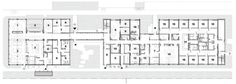
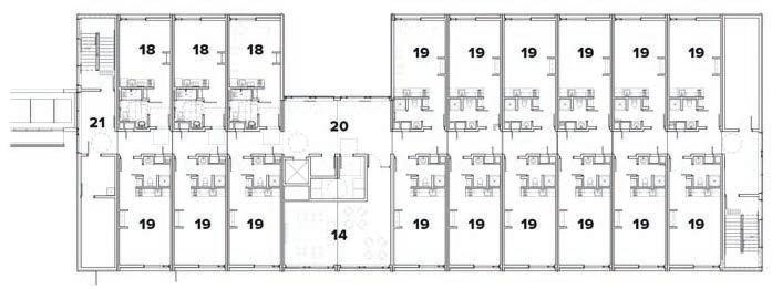
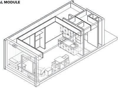
Include common spaces - these spaces may range from courtyards to shared kitchens to common recreation.

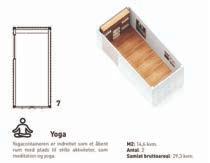
Accomodate individuals - individuals may have single studios for themselves, a shared bedroom and living space, or somewhere in-between.
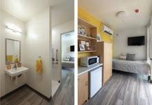
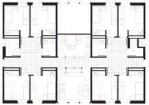
Accomodate refugees, families, or youth
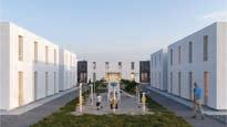
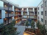
Have fixed or flexible space - flexible space changes with the needs of the inhabitants, community, or building program shifts.
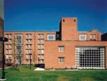
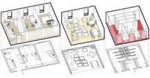
Are mix-use - integrating the building more into the surrounding area, rather than isolating
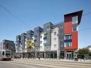
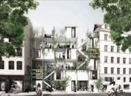
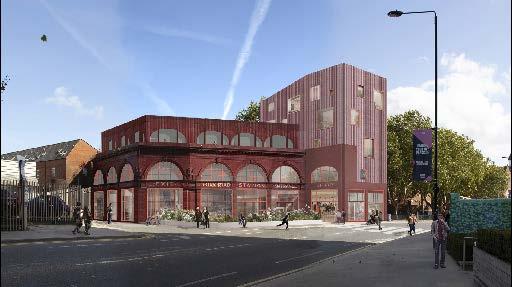
Morris + Company’s “Hidden Homeless” is a project proposal for the rennovation of an old London metro station into transitional housing for London’s homeless population. While not an urban infill, the project is similar to the Flint site as they are both adaptive reuses of historic buildings. Morris + Company entirely reworked the interior and created a modern addition to the top of the building, but still maintained the historic facade. The “Hidden Homeless” project is appealing due to its adaptability towards each individual’s circumstances/needs as well as a design that promotes community engagement.
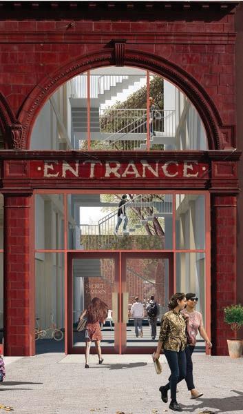
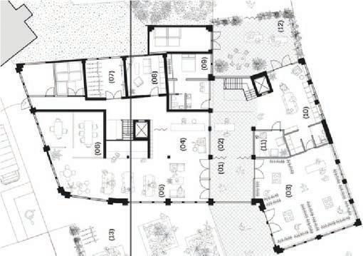
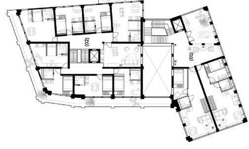
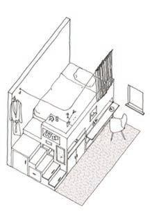
The building holds both residential space and commercial space in the form of a thrift shop. The thrift shop provides an affordable shopping option for the building residents, and intertwines the building into the surrounding community by attracting others to the building.
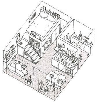
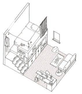
The designers recognized that not everyone in need of transitional housing will have the same circumstances and needs - some people may need to stay for a week, others for a year. Therefore, the building is outfitted with different residential layouts to serve different lengths of stays and amounts of people (single units vs. family units).
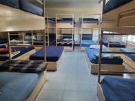

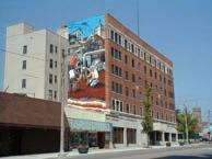
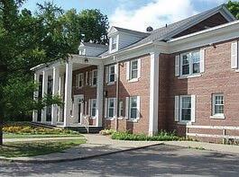
Centered Location
Active Frontage
Community needs
Residential Context
Inc. homeless rate
Inc. Immigrant communities
London, UK
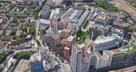
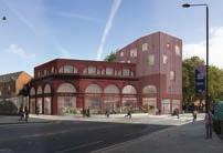
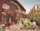
Heavy Residential Area
Lack Residential Buildings (Downtown Area)
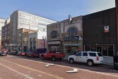
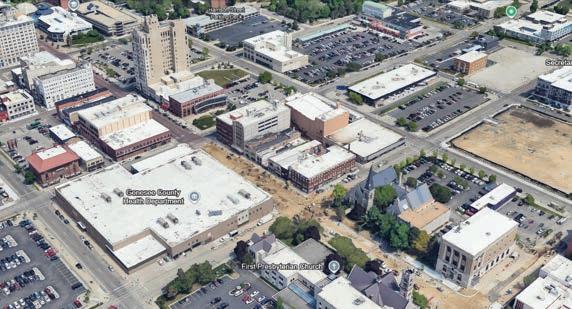
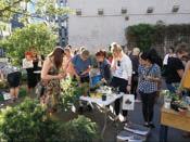
Provide shelter and basic needs
Re-adaptation and education services
Enhance inter-cultural relationships
Increase commercial activity
Local community engagement
Retain population and welcome the new
Our team goal was to meet with Adil Mohammed, Program Director and Co-founder of International Center of Greater Flint , in order to gain a wide range of information and perspectives regarding some of the immigrant communities, and other communities in need of transitional housing. More specifically, we wanted to gain insight on the needs of potential tenants and occupants who would use the transitional housing. From contacting and interviewing Adil, we hope to make informed decisions that will help guide our future architectural proposal and support the Flint community in the most efficient way possible.
The engagement plan was to contact a constituent who is knowledgeable about the communities in Flint, where they are located, how they interact, who may be in need of transitional housing, and the current situation of transitional housing in the area. The chosen constituent was Adil Mohammed, who is the Program Director and Co-founder of International Center of Greater Flint. In this position, Adil is familiar with the different immigrant communities around Flint, and their needs. The initial contact with Adil was during our site visit. Then we contacted him through email, to set intentions and coordinate a time for a meeting to discuss more in depth about our topic. The most convenient and effective medium for the interview was through Zoom, this way we could record the meeting and review notes.
Assets:
There are many strong pockets of immigrant and other communities in the area of Flint, Michigan. Flint has 3 institutions of higher education, which brings more people into the area for education, and potential jobs.
Needs:
Especially the immigrant communities are in need of a transitional housing, and a space where all communities can interact and mingle. Currently, there is a lack of connection between the different pockets of people and a lack of transitional housing specifically for immigrants.
Obstacles:
Because the pockets of communities are spread around Flint, it can be difficult to bring them together. Furthermore, each community may have different needs, which could pose a challenge to cater to all. Another obstacle for this project may be the proximity of the site to different community groups. The site location may be less accessible to some groups.
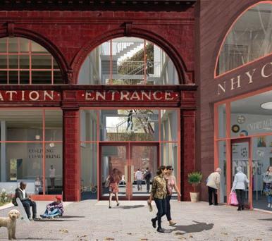
Integration of semi-public use and transitional housing

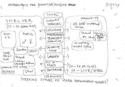
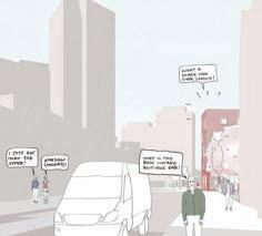
Community integration & support
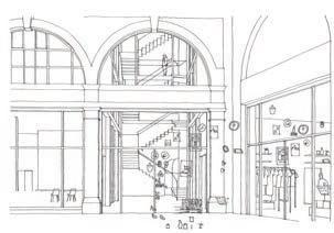
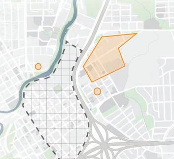
Interstate divides cultural centers and downtown
What went well?
▪ Our engagement goals were achieved through our conversations with Adil. He was able to provide useful information regarding the immigrant population in Flint and their needs.
▪ Adil also provided suggestions on how the site may better serve the population.
What did not work out?
▪ There were some questions from our interview that were left unanswered, including how transitional housing may affect housing need in other areas, and what resources in Flint are underutilized and how that might be changed.
▪ Overall, this engagement went very well. In the future, it may help to gain insight from other community individuals, and other locals in the area to analyze different perspectives on the subject. Also, Adil focuses on the immigrant community, but there was little to no information on the needs of non-immigrant community.
- There are multiple immigrant groups that are spread around Flint, and the downtown area is a sort of meeting point for the different groups.
- Immigrant population over the last decade has been increasing in Genessee County, specifically Indians, Muslims, new business owners, and healthcare providers.
- Some locals may feel threatened by the increase of new immigrants to the area.
- Better educational facilities and housing would be helpful to the community and economy.
- Many people, including locals and immigrants use the cultural center, however, access by public transportation is inefficient.
- There s a lack of transitional housing to serve immigrants while they establish a permanent home in Flint.
- Incorporate a way for the public to interact with the building, for instance a restaurant, retail, or event space.
- Transitional housing should include support for immigrants including food, employment support, and access to outside resources like government facilities and education/training.
- Obstacles include public transportation access between site, cultural centers, and the immigrant communities. Another obstacle may be the negative feelings that some locals have toward immigrants.
Macro Scale Study
Building Use Downtown Vs Suburbs
Key Locations
Distances to the Site
Micro Scale Study
Building Use
Key Locations
Distances to the Site
Third Place
Active Hours
Activities and Festivals
Macro Scale
Macro Scale
UNIVERSITIES
UM Flint
Kettering U
Mott CC
GOVERNMENTAL
CULTURAL
Cultural center
Library
Museums
HOSPITALS
McLaren Flint Hurley Medical Center
RECREATION
DOWNTOWN AREA
Macro Scale
Macro Scale
UNIVERSITIES
UM Flint
Kettering U
Mott CC
GOVERNMENTAL
CULTURAL
Cultural center
Library
Museums
HOSPITALS
McLaren Flint Hurley Medical Center
RECREATION
DOWNTOWN AREA
Micro Scale
RESTAURANT
INTERIOR RESTAURANT
RESIDENTIAL
COMMERCIAL
RELIGIOUS
GOVERNMENT
EDUCATION
TRANSIT
The different types of buildings are often present in clusters. There is a cluster of religious buildings south of the site. There are also numerous government buildings surrounding the site. However, there seem to also be a huge portion of vacant spaces.
Although there are a variety of building types surrounding the site, there is also a large amount of space that is either parking or vacant. This space can be useful as parking if the city demands for it but the space would be better used if there are services offered.
Within a ~2 block distance of our site, several types of third-spaces exist in the form of green/outdoor spaces, cafes and bars, and relgious buildings. They all have limits - outdoor spaces are less enjoyable in wintertime, cafes and bars require spending money, and religious buildings are irrelevant to those who don’t practice the particular religions. While there are a variety of third-places, there are also large areas of the downtown that are void of year-round third-places for people to gather.
Outdoor spaces
Notable commercial/restaurants
Religious institutions
Recreational
Having key locations within close walking distance (about 2 city blocks, or 1,200 feet) is important to provide residents of our site with ammenities that do not require car/public transportation to get to. The site bene ts from close proximity to the city court and farmer’s market, as well as most of the downtown retail/restaurant scene. However, there are gaps in ammenities like schools and healthcare locations within this mico urban scale radius.
Outdoor spaces
Notable commercial/restaurants
Religious institutions
Recreational
Governmental
WEEKDAYS
Mid-day
WEEKENDS
Mid-day
MIXED DAYS
Morning
Mid-day
Evening
All Day
Buildings are primarily open during mid-day, roughly 9am-5pm. Many are open on select days, not just week days or weekends. There is a lack of businesses that are open in the evening.
Battle of the Bubble GFAC Member Artist Exhibition
BttB Chrome and Ice
American Artists of Michigan Black History in American Music
Saginaw Spirit at Flint Fire-birds
Patrick’s Day Celebration Flint Farmers Market Applewood Estate
Junteenth
Bricks
Bricks
Our group aimed to better understand the significance and function of Back to the Bricks, how this event impacts the community, and how other events may operate. We met with Amber Taylor on an online interview to ask about how this event serves the community, and what services may be missing for events in Flint. Insight from the interview is incorporated into Work 2, and will inform the future design to better serve the area. The goal of this engagement was to gain insight on how effective current events in Flint are, and how other events may be successful.
The engagement plan was to contact a constituent that is knowledgeable about the communities and events in Flint. The constituent should be familiar with how the community interacts, and what is effective or not effective. We researched constituents to evaluate who was appropriate to contact and would provide relevant insight. We chose to contact Amber Taylor, who is the executive director of Back to the Bricks. We initially contacted Taylor through email, to set intentions and coordinate a time for a meeting. The most convenient and effective medium for the interview was through Zoom, this way we could record the meeting and review notes.
Assets:
Back to the Bricks is a prominent event in Flint, MI. This event and others bring revenue and spread word about the city. Events primarily occur in the downtown area. Having University of Michigan, Flint in close proximity may bring more college students into the area and to events.
Needs:
Potential needs include access to events and increasing awareness of events.
Obstacles:
Some events may lack coordination, and not run as smoothly as they could. Funding can be an issue for some events, as well as raising awareness of the event for more community engagement. Some venues may be underutilized because of the lack of year-round use. Another obstacle may be transportation and access to event locations.
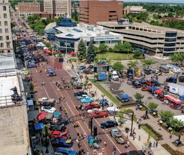
Back to the Bricks


Crim Festival of Races

- Back to the Bricks is a large-scale and well-known event around the Flint area that benefits the local economy and increases recognition of Flint - Flint has many events that bring together different parts of the community year-round
- Event planners should be open-minded about time frame and location. For instance, a vacant space in a mall may be a useful and effective year-round event location
- Allow area for year-round events. Have indoor and outdoor options.
- Allow access for different types of people and needs.
- Some barriers may include not having connections with the community, or the social media connections to promote events
What went well?
▪ Most of our engagement goals were achieved. Our main goal was achieved, by contacting and interviewing Amber Taylor.
▪ From Amber Taylor, we learned more about Back to the Bricks and how other events may run in Flint.
What did not work out?
▪ We initially planned to contact more members of the community through a survey, but we decided to prioritize the constituent contact. In the future, if we want to connect with more of the community, it would help to brainstorm more engagements and put a plan into action early.
▪ We did not get significant information about specific community groups that interact with different events. Also, Taylor did not provide information about what Flint is lacking because she chose to focus on the positives of what Flint is doing well. Some ways that we could have gotten more information may have been to re-word certain questions to have a less negative undertone, or to have a more in-depth conversation with the constituent. Having multiple constituent contact may have also helped fill the information gaps.
Open Lot Adjacent to Building - potential use for indoor/outdoor events
Back to the Bricks Area - Primarily along Saginaw Street Downtown
BENDING BOX CUTTER Spring 2023
BENDING
BENDING