IJSER
In IR communication, the signal received by the receiver depends on the distance between the transmitter and receiver and the power of the transmitted signal. The power of the transmitted signal depends on the magnitude of the input current to the transmitter.
1.2. Methodology
The purpose of this paper is to investigate the effect of the distance of separation between the IR transmitter and IR receiver and IR transmitter input current on the magnitude of the voltage detected by the IR receiver for Line-of-Sight IR propagation. The methodology applied in this experiment is the design of the transmitter and receiver circuits and the measurement of experimental parameters.
1.3. Design of the System
· Hyginus Udoka Eze is a masters’ degree holder in electronic engineering in University of Nigeria, Nsukka, Nigeria E-mail: ezehyginusudoka@gmail.com
· Samuel C. Olisa is a masters’degree holder in electronic engineering in University of Nigeria, Nsukka. Nigeria. E-mail: samuel.olisa@unn.edu.ng
· Martin C. Eze is currently pursuing Phd program in electronic engineering in University of Nigeri Nsukka, Nigeria, E-mail: martin.eze@unn.edu.ng
· Bassey Okon Ibokette is a masters’ degree holder in lectronic engineering in University of Nigeria, nsukka. Nigeria
· Samuel Anezichukwu Ugwu is currently pursuing Phd program in electronic engineering in Univeristy of Nigeria, Nsukka. Nigeria. E-mail: tophersammy@yahoo.com
· Jonathan Ikechukwu Odo is a masters’ degree holder in electronic engineering in Univeristy of Nigeria, Nsukka, Nigeria. E-mail: ik2244more@gmail.com
The electrical parameters of the components used in the research are shown in Table 1. The circuit diagram of the transmitter is shown in Figure 1. The input signal to the BC338 transistor is a square wave with a period of 10µs (f=100KHz).
In Figure 1, the magnitude of current through IR transmitter (IIR) and the Resistance (R2) of the resistor connected to the base of the transistor are calculated from (1) and (2) respectively. In (1), Vcc is the DC voltage supply to the transmitter circuit, VIRF is the barrier voltage of the IR transmitter, VCEsat is the collector-emitter saturation
International Journal of Scientific & Engineering Research, Volume 7, Issue 10, October-2016 ISSN 2229-5518
642
voltage, R1 is the resistor that limits the current flowing through the IR transmitter and VR1 is the voltage drop across R1
= = (1)
On the other hand, vi is the switching voltage applied to the base of the transistor, VBE is the base-emitter barrier voltage of the transistor and IBsat is the saturation base current of the transistor.
= −
(2)
The value of R2 is calculated as 86Ω and 100Ω were used in the experiment. The values of R1 used in the experiment are 27Ω, 37Ω 47Ω, 57Ω, 67Ω, 77Ω, 87Ω, 97Ω, 107Ω, and 117Ω
The receiver section of the system used in the experiment is shown in Figure 2. An op-amp used is in the voltage follower configuration and it is connected to the output of the IR receiver to prevent loading.
1.4. Data Measurement
In the transmitter circuit, a high precision potentiometer was used to vary the magnitude of current (IIR) through the IR transmitter. A high precision voltmeter was used to measure the voltage drop (VR1) across the potentiometer resistor (R1). The current through the IR receiver is computed using (3). =
(3)
The output voltage (V0) of the receiver circuit is measured using a high precision digital voltmeter.
1.5. Results and Discussion
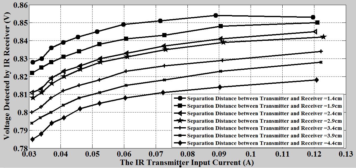
The effect of IR transmitter input current on the voltage detected by IR receiver is shown in Figure 3. From the figure, it was observed that the voltage detected by the IR receiver increases with the increase in the IR transmitter
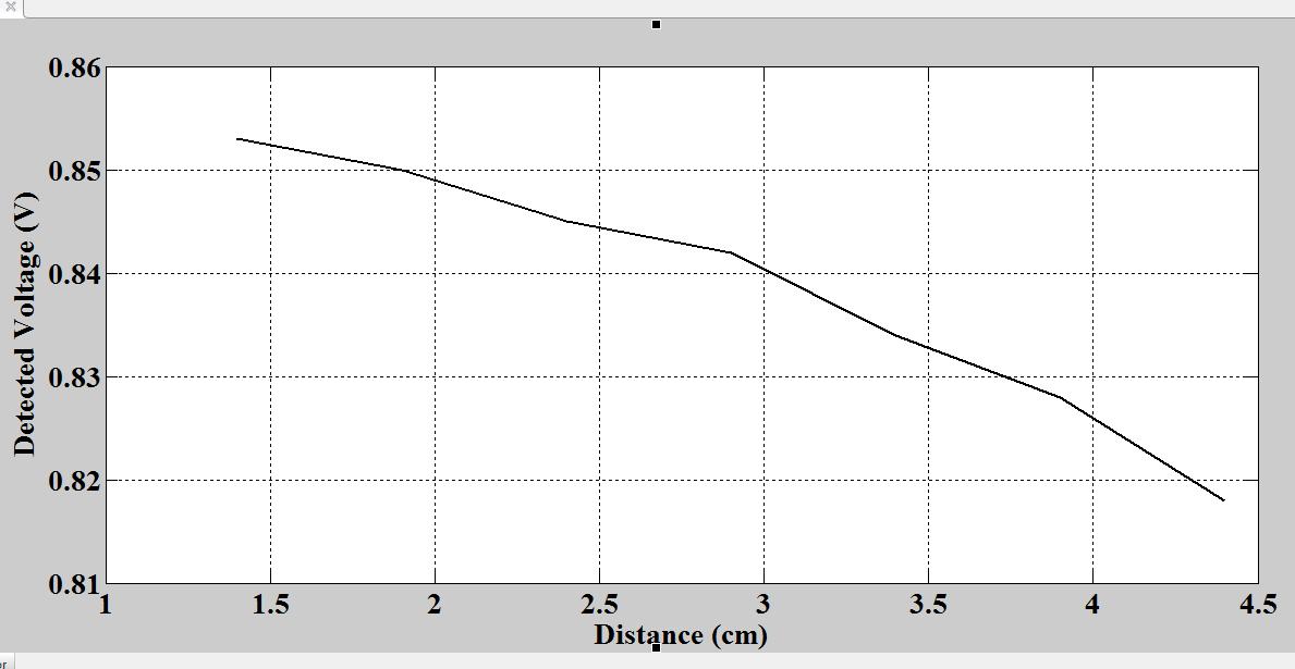
input current. This was because the increase in IR transmitter input current increases the power of the transmitted IR signal. It also showed that the voltage detected by IR receiver was inversely proportional to the distance separating the IR receiver and IR transmitter. The effect of separating distance on the detected voltage became very clear in Figure 4. From the Figure, it was clearly observed that the detected voltage varies inversely as distance. This simply implies that the lower the distance the higher the detected voltage. Therefore, distance has a proficient impact/effect on detected voltage.
1.6. Conclusion
IJSER
In this research paper, the effect of IR transmitter input current and the separating distance between the IR receiver and transmitter on the voltage detected by IR receiver was investigated. From the work, it was observed that the voltage detected increased with the increase in the IR transmitter input current. The paper also showed that the voltage detected was inversely proportional to the distance separating the transmitter and the receiver. This implied that to transmit IR signal to a long distance, the transmitter input current must be high to ensure that the IR signal has high power.
Table 1: The Electrical Parameters of the Components
Wavelength= 940nm Angle =250 FDS100 V0max=1. 0V I0max=3.0 mA dmax=30cm R1 (Potentio meter) 643
100KΩ R2 (Fixed) 100Ω LM741 vi=±18V V0=±15V Voltage supply=±20V
International Journal of Scientific & Engineering Research, Volume 7, Issue 10, October-2016 ISSN 2229-5518
BC338 [4] ICsat=500 mA IBsat=50m A VCEsat=0.7V VBE=0.7V IR533C [5] VIRF=1.2 V Ipulse =1000m A IDcmax=10 0mA
Figure 1: The Transmitter Circuit for the Experiment
International Journal of Scientific & Engineering Research, Volume 7, Issue 10, October-2016 ISSN 2229-5518
5v
v
644
Figure 2: The receiver circuit for the experiment VCEsat VBE BC338 R2 R1 Signal from Frequency Generator VCC GND
T
i IIR IR Transmitter IR Signal VR1 VIRF+ VCC GND V0 LM471 IR signal IR Receiver VS=-VCC
IJSER
Figure 3: Plot of Detected Voltage by IR Receiver against IR Transmitter Input Current for Different Separating Distances.
IJSER
Figure 4: Plot of Detected voltage against distance at f=100KHz and I=120mA
References
[1] M. R. Tavares, R. T. Valadas, and M. D. O. Duarte, “Performance of wireless infrared transmission systems considering both ambient light interference and inter-symbol interference due to multipath dispersion,” in Conference on Optical Wireless Communications, 1998, vol. 3532, no. November, pp. 82–93.
[2] V. Jungnickel, V. Pohl, S. Nönnig, and C. von Helmolt, “A physical model of the wireless infrared communication channel,” IEEE Journal on Selected
Areas in Communications, vol. 20, no. 3, pp. 631–640, 2002.
[3] N. Barbot, S. S. Torkestani, S. Sahuguede, A. Julienvergonjanne, and J. Cances, “Outage Capacity of Mobile Wireless Optical Link in Indoor Environment,” in Advanced International Conference on Telecommunications, 2012, no. 8, pp. 133–137.
[4] “Npn silicon Amplifier Transistor,” Motorola Semiconductor Technical Data, pp. 1–5, 1996.
[5] “5mm Infrared LED IR533C,” EVERLIGHT DATASHEET, pp. 1–8, 2013.
International Journal of Scientific & Engineering Research, Volume 7, Issue 10, October-2016 ISSN 2229-5518
645
