Development of Aduino Based Software for Water Pumping Irrigation System
Hyginus Udoka Eze, Melvina Obiageli Onyia, Jonathan Ikechukwu Odo, Samuel Anezichukwu Ugwu
Abstract-This research paper undertakes the development of water pumping system that was capable of automatically managing water budgets from a reservoir through a microcontroller (Arduino Uno Microcontroller) subsystem. A user-friendly and efficient water management system that has the capability to irrigate farms based on automated algorithm, logic and electronic circuitry was developed. The Object Oriented System Analysis and Design (OOSAD) methodology was used for the analysis and development of the system under consideration. The software application communicates directly with a microcontroller unit and uses manual override approach in some cases to manage water budgets. The water-level sensor and the soil-moisture-content sensor check the level of water storage and soil moisture content in a reservoir and reports to an electronic controller respectively. The water pumping software for irrigation system was developed using C# for Windows application development, establishing routines and relationships, Embedded C was used in defining status and processes in the Arduino Uno microcontroller, PHPMyAdmin as a database management system and MYSQL relational database server version 5.5 as the backend for storing user inputs from the frontend. The water-pumping software for irrigation system provides the user interface providing irrigation in gardens or farms. The system was able to pump water from reservoir which can be used to irrigate farms or gardens.
Index Terms: Arduino Microcontroller, Hardware, Sensor, Software, Water Pumping System
1.1. Introduction
Over 70% of planet earth, as well as over 70% of the human body is water. Water supply is critical to sustainable development and economic competitiveness of any nation.
————————————————
• Hyginus udoka Eze is currently pursuing Phd program in Electronic Engineering in University of Nigeria, Nsukka. Nigeria. E-mail: ezehyginusudoka@gmail.com
• Samuel Anezichukwu Ugwu is currently pursuing Phd program in Electronic Engineering in University of Nigeria, Nsukka. Nigeria. E-mail: tophersammy@yahoo.com
• Jonathan Ikechukwu Odo is a masters’ degree holder in Electronic Engineering in University of Nigeria, Nsukka, Nigeria. E-mail: ik2244more@gmail.com
• Melvina Obiageli Onyia is a masters’ degree holder in Electronic Engineering in University of Nigeria, Nsukka, Nigeria. Email:melvinaoby@gmail.com
Population surge, industrialization and rising standards of living, have put water demand on the rise, though without corresponding increase in the quantity of the resource [1].
Water pumping is required in situations where site conditions do not favor the use of gravity supply. This may occur in irrigation
or water supply projects. In either case, gravity systems tend to involve high capital cost but low operating cost. On the other hand, pumping systems tend to require lower capital cost but high operating cost. The choice between gravity supply, and pump fed supply is an economic one. When the economic case is not obvious, then the economic viability of each alternative must be established, and the economically superior alternative chosen [2]
Water demand is determined by segregating the total demand into categories such as Irrigation demand, Domestic demand, Industrial demand, Commercial demand and Institutional demand
For irrigation, the water demand is derived from the total area to be irrigated and the water required per unit of area irrigated. The water demand required per unit area irrigated depends on the crop, the climatic conditions, and the soil conditions.
For categories of demand except irrigation, the population to be served and its per capita water consumption is estimated, and from these data, the aggregated water demand is
International Journal of Scientific & Engineering Research Volume 8, Issue 8, August-2017 1384 ISSN 2229-5518 IJSER
2017 http://www.ijser.org
©
——————————
IJSER
computed. The water quality for categories of demand other than irrigation will generally be to human health standards [3] In practice, demand for irrigation will usually be isolated and designed for separately, because the location where it occurs and the water quality demanded is often different [4].
Computer software/simulation models are widely used by water authorities around the world for planning and management of water supply systems. These water supply systems consist of ‘nodes’ such as reservoirs, demand centers, stream junctions and pipe junctions, and ‘carriers’ such as rivers and pipes. They supply irrigation and urban water demands, meet environmental flows, and provide releases for hydropower generation and other uses [5]
This water pumping/irrigation software is about the use of computer and supporting technology to provide effective, efficient and economically viable alternative to the current manual/semi-automated systems and leveraging positively on water budget. It is a system that is vast, adaptable and scalable making it suitable for domestic and commercial water budget planning/management [6]
fertigation (mixing fertilizer with irrigation water) and maintenance. Little documentation is found in Nigeria especially in Akwa Ibom State to be reviewed. There are some irrigation drawbacks in Nigeria such as no data documentation for planting planning, no reports which could sufficiently be used for fault tracing and system auditing, expensive to operate and maintain and wastage of water instead of conserving the resource.
This paper solved such problem by automating/computerizing irrigation so that some of the drawbacks will be taken care of. It satisfies the works of administrators, engineers and farmers. With an automated irrigation software system, farmers and stakeholders can easily interact with system, manage their water budget, improve their crop yield and optimize their profitability.
IJSER
Nigeria as a case of study in this paper is among nations that are at the moment technically unable to meet its food needs from rain-fed production at low level of inputs and appears likely to remain so even at intermediate levels of rain in the mid-term before 2025. Water is still a limiting factor in much of the country but most especially in the northern semi-arid and dry sub-humid zones in the north.
A computerized irrigation system plays a great role in simplifying the job of a farmer and satisfying the needs of stakeholders in a farm. It consists of a combination of hardware and software that act as a supervisor with the purpose of managing irrigation and its related practices such as
2.0 Methodology
The functional and non functional requirements of the system are discussed in this section including the software and hardware components.
• Software Components
Software components include embedded software written for the controller and the User Interface Application which is written using C#. There are varieties of programming languages that can be used to instruct the controller viz Assembly Language, Embedded C, Java, Python etc. Embedded C is the most commonly used programming language and hence it is used for this particular project [7].
• Embedded C
Embedded C is small and reasonably simpler and C compilers are available for all embedded devices existing. Unlike assembly, C has advantage of processor independence and offers more flexibility. It also supports low level bit wise data manipulation. Considering all these benefits, Embedded C is used as programming language for the microcontroller.
International Journal of Scientific & Engineering Research Volume 8, Issue 8, August-2017 1385 ISSN
IJSER © 2017 http://www.ijser.org
2229-5518
The functional and non-functional requirements of the system are described and modeled.
•
Functional Requirements
The functional requirements of the system includes Select a farm/field, Activate the external controller, Irrigate the farm, Generate report
•
Non-Functional Requirements
Security requirements are important factors in this system as important data will be stored in the database. User validation will be done during Login to ensure that the user is valid and that the user has access to the software. There is no provision for general user.
The system will have consistent interface formats and button sets for all forms in the application. Application will have a formbased interface for data entry and viewing formats, and will generate reports that are formatted in a table and that should look like the existing manual report formats for user friendliness.
The system will be easily maintained by the developer or other authorized trained person and it quickly generates reports and activate the irrigation system
The Arduino Uno is a microcontroller board based on the ATmega328. It has 14 digital input/output pins (of which 6 can be used as PWM outputs), 6 analog inputs, a 16 MHz crystal oscillator, a USB connection, a power jack, an ICSP header, and a reset button. It contains everything needed to support the microcontroller; it simply connects to a computer with a USB cable or can be powered with a AC-to-DC adapter or battery to get it started. It features the Atmega8U2 programmed as a USB-to-serial converter.
Power
The power source is selected automatically. The adapter can be connected by plugging a 2.1mm center-positive plug into the board's power jack. The board can operate on an external supply of 6 to 20 volts. The recommended range is 7 to 12 volts.
IJSER
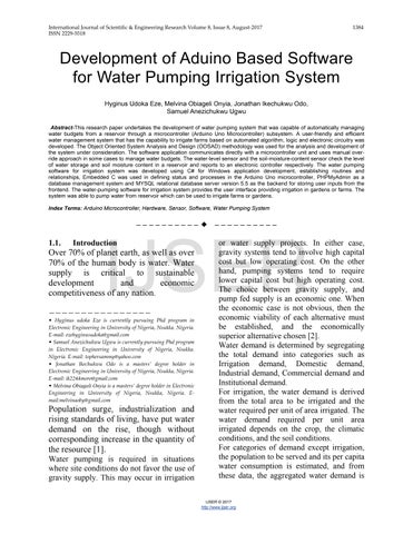
Figure 1: Schematic of the Computerized Irrigation system
2.2. Hardware Components
The hardware components used for this paper are as shown below:
• Microcontroller Arduino Uno
Memory
The Atmega328 has 32 KB of flash memory for storing code (of which 0.5 KB is used for the bootloader); It has also 2 KB of SRAM and 1 KB of EEPROM (which can be read and written with the EEPROM library).
Input/output
The Uno has 6 analog inputs, each of which provides 10 bits of resolution (i.e. 1024 different values).
Communication
The Arduino Uno has a number of facilities for communicating with a computer, another Arduino, or other microcontrollers. The ATmega328 provides UART TTL (5V) serial communication, which is available on digital pins 0 (RX) and 1 (TX). An ATmega8U2 on the board channels this serial communication over USB and appears as a virtual com port to software on the computer. The '8U2 firmware uses the standard USB COM drivers, and no external driver is needed. However, on Windows, an *.inf file is required.
International Journal of Scientific & Engineering Research Volume 8, Issue 8, August-2017 1386 ISSN
IJSER © 2017 http://www.ijser.org
2229-5518
The Arduino software includes a serial monitor which allows simple textual data to be sent to and from the Arduino board.
Programming
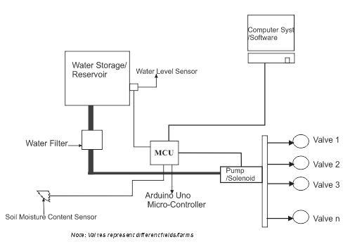
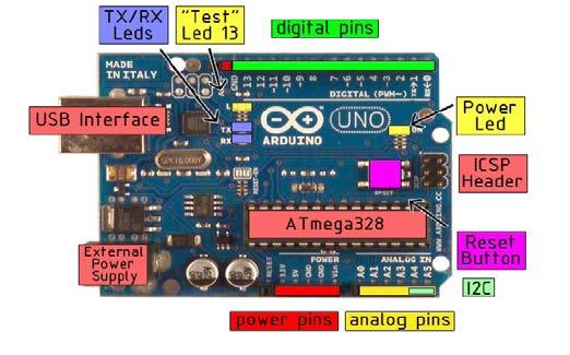
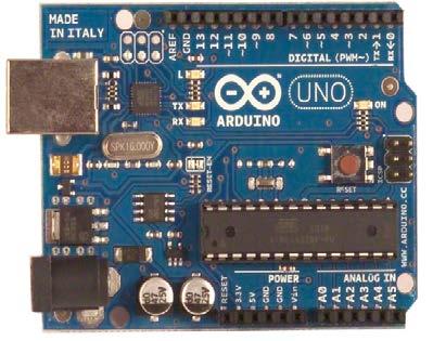
The Arduino Uno can be programmed with the Arduino software. The ATmega328 on the Arduino Uno comes pre-burned with a boot loader that allows you to upload new code to it without the use of an external hardware programmer. It communicates using the original STK500 protocol (reference, C header files). The bootloader can also be bypassed and the microcontroller programmed through the ICSP (In-Circuit Serial Programming) header. Figures 2 and figure 3 show the pictures of the Arduino Uno Microcontroller and the board components layout
Level Sensor module to receive and send the information; second port interfaces to the DC motor operated solenoid to send the actuation signal while third port connects to the Moisture Content sensor to receive the monitored signal [8].
• Solenoid Valve
Installed DC motor operated valve serves the purpose of operating the Actuator Node. Incorporated DC motor is compatible with 12V DC supply. DC motor operated valves are interfaced with the controller node to control the flow of water. The Solenoid valve has an orifice of 16mm; pipe size of 1/2”; operates within temperature range of50C to 1000C and a Pressure of between 0Kg/cm2 and 10Kg/cm2 [9]
IJSER
A solenoid valve is an electromechanically operated valve. The valve is controlled by an electric current through a solenoid: in the case of a two-port valve the flow is switched on or off; in the case of a three-port valve, the outflow is switched between the two outlet ports. They are found in many application areas. Solenoids offer fast and safe switching, high reliability, long service life, good medium compatibility of the materials used, low control power and compact design.
A 2-way valve, with 2 ports was used; if the valve is open, then the two ports are connected and fluid may flow between the ports; if the valve is closed, then ports are isolated. If the valve is open when the solenoid is not energized, then the valve is termed normally open (N.O.). Similarly, if the valve is closed when the solenoid is not energized, then the valve is termed normally closed.
Figure 3: Arduino Uno board with component layout
The serial interface is programmable for three duplex UART modes for serial I/O. The first port is used to interface the Water
A small solenoid can generate a limited force. An approximate relationship between the required solenoid force Fs, the fluid pressure P, d is the diameter of the solenoid and the orifice area A for a direct acting solenoid value is:
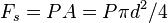
International Journal of Scientific & Engineering Research Volume 8, Issue 8, August-2017 1387 ISSN 2229-5518 IJSER © 2017 http://www.ijser.org
Figure 2: Picture of the Arduino Uno Microcontroller
•
Soil Moisture Sensor
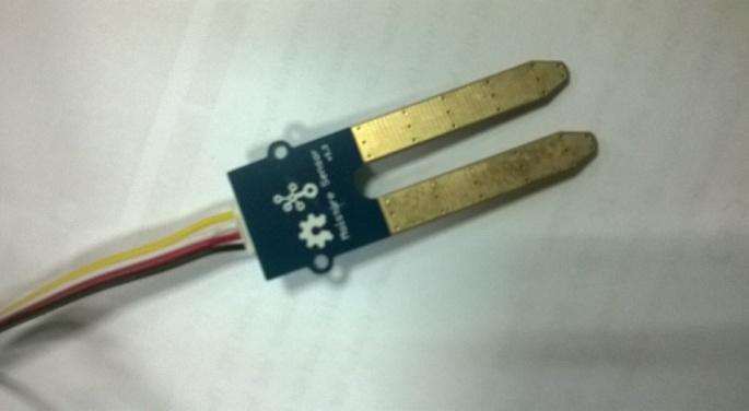
Soil moisture sensors typically refer to sensors that estimate volumetric water content. The relation between the measured property and soil moisture must be calibrated and may vary depending on environmental factors such as soil type, temperature, or electric conductivity [10]. Measuring soil moisture is important for agricultural applications to help farmers manage their irrigation systems more efficiently. Knowing the exact soil moisture conditions on their fields, not only are farmers able to generally use less water to grow a crop, they are also able to increase yields and the quality of the crop by improved management of soil moisture during critical plant growth stages [11]. For this project, Grove Moisture Sensor Eagle V1.3 was used. It measures soil moisture content based on soil resistivity and it has the following parameters [11]: Dimension: 2.0cm x 6.0cm Supported Platforms are Arduino, Raspberry Pi and TI Launch Pad
Table 2: Crop Water Requirement Crop Water Requirement(mm/day) Maize 500 – 800mm Cassava 500 – 700mm Plantain 1200 – 2200mm The data for the crop water requirement is a published [12]
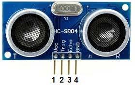
• Water Level Sensor
An ultra sound distant measurement system was used to sense the water level in the reservoir. The particular component used was HC-SR04 as shown in Figure 5
Figure
International Journal of Scientific & Engineering Research Volume 8, Issue 8, August-2017 1388 ISSN
IJSER © 2017 http://www.ijser.org
2229-5518
of Soil Moisture Sensor
1: Soil Moisture Content Parameters
Parameter Mini mum Typic al Maxi mum Unit
Figure 4: Picture
Table
Item
Voltage - 3.3 - 5 V Current - 0 - 35 mA Outputs Sensor in Dry soil 0 - 200 Nil Sensor in humid soil 300 - 700 Nil Sensor 700 - 950 Nil in water
1. Vcc 5V
2. Trig
3. Echo
4.
Electrical Parameters Electrical Parameters
Operating Voltage Dc-5V Operating Current 15mA Operating Frequency 40KHz Highest Range 4M Nearest Range
IJSER
5: Picture of the Water Level Sensor (HC-SR04) HC-SR04 Specifications Type Pin Symbol Pin Function Description HC –SR04
Power supply
Trigger pin
Receive Pin
GND Power ground
HC-SR04 Ultrasonic Module
2cm
Measuring Angle 150 Input Trigger Signal
10us TTL pulse
The power pins are VCC and GND. The ultrasonic range finder works on 5V of power. This is connected to VCC. GND is connected to ground.
The trigger (trig) pin is the pin needed to trigger or start the sensor into ranging mode. A 10-microsecond pulse needs to be sent to the trigger pulse in order for the sensor to be triggered on. Without this pulse and the sensor will never go into ranging mode to detect objects. Therefore, this is a crucial pin for that reason. When it receives this pulse, it sends out 840KHz pulses to detect an object and waits to listen back for these sound pulses.
The echo pin is the pin that sends the result of the sent out pulses. If the pulses have been received back, this means that the pulses bounced off of an object and came back to the sensor, which means an object has been detected. The echo pin then returns the pulse representing the amount of time it took for the pulses to be received back. With this time, we can compute the distance the object is from the sensor. If no object has been detected, the pulses are not received back, so the echo pin returns no pulse or a 0. Test distance = (high level time × velocity of sound (340M/S) / 2 [13].
Design goals describe the qualities of the system that developers should optimize. Such goals are normally derived from the non-functional requirements of the system.
Design goals are grouped into five categories known as Performance, Dependability Maintenance and End User Criteria.
Performance Criteria
The part of the system to be used for the irrigating the farm should have a fast response time (real time) with maximum throughput. Furthermore, the system should not be taking up too much space in memory. The developer has chosen fast response time over throughput and hence the system should try to be more interactive. In the case of the logging subsystem, the system should be more reliable in order to satisfy the constraints than fast response time.
IJSER
2.3 SYSTEM DESIGN
In the previous section we have identified the functional and non-functional requirements of the system. The following are discussed in this section: design goals, system architecture, system decomposition, deployment and database design.
• Design Goals
Dependability
The farm needs the system to be highly dependable as it is expected to be used by non-IT professionals. The system should be robust and fault tolerant. Furthermore, as the system is handling sensitive data (irrigation activity log) of the farm, reasonable emphasis should be given to security.
Maintenance
The system should be easily extensible to add new functionalities at a later stage. It should also be easily modifiable to make changes to the features and functionalities.
End User Criteria
Usability: Usability is the extent to which a product can be used by specified users to achieve specified goals with effectiveness, efficiency and satisfaction in a specified context of use. From the end users’ perspective the system should be designed in such a way that it is easy to learn and use, efficient and having few errors if any.
International Journal of Scientific & Engineering Research Volume 8, Issue 8, August-2017 1389 ISSN 2229-5518 IJSER © 2017 http://www.ijser.org
Trade-off is inevitable in trying to achieve a particular design goal. One best case is the issue of security versus response time. Checking User-Id and Password before a member can enter to the Software for Irrigation creates response time problem/overhead. The other case is the issue of response time versus quality. There is some amount of time taken by the system to generate the log showing the correctness of parameters before pumping/irrigating a particular field. So the user has to wait a little after telling the system to irrigate a particular field and getting the result to get the farm irrigated.
• Architecture of the System
The proposed automated system is expected to replace the existing manual system The architecture used for the system is a 2-tier Client/Server Architecture.
The data tier maintains the applications data such as error logs, duration of irrigation, date of irrigation data etc. It stores these data in a relational database management system (RDBMS).
farm or to retrieve data from the database. Business rules enforced by the business logic dictate how client (user) can and cannot access application data and how applications process data.
The client tier is the applications user interface containing data entry forms and client side applications. It displays data to the user. Users interact directly with the application through user interface. The client tier interacts with the database/application server to make requests and to retrieve data from the database. It then displays to the user the data retrieved from the server
IJSER
The first tier implements the business logic, controller logic and presentation logic to control the interaction between the application’s clients (user) and data. The controller logic processes client requests such as requests to view error log, irrigate
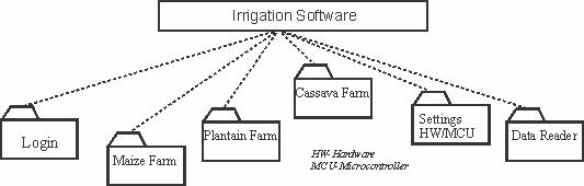
Figure 7: Layered Representation of the system
International Journal of Scientific & Engineering Research Volume 8, Issue 8, August-2017 1390 ISSN 2229-5518 IJSER © 2017 http://www.ijser.org
START
INITIALIZE IF USER VALID
Start Up Baud Rate Comport
Do Irrigation for Maize, Cassava, Plantain IF Maize Click
YES NO NO
IF Plantain Click Read ComPORT Check Conditions IF ComPORT =1,2,3 TurnOnRelay/Pump END
IF Cassava Click
Figure 6: System Flowchart
• Subsystem Decomposition
Subsystem decompositions will help reduce the complexity of the system. The subsystems can be considered as packages
holding related classes/objects [14]. The Software for Water Pumping (Irrigation) System (SWPIS) under consideration is decomposed into subsystems as shown in
International Journal of Scientific & Engineering Research Volume 8, Issue 8, August-2017 1391 ISSN 2229-5518 IJSER © 2017 http://www.ijser.org
IJSER
Figure 7. These subsystems may be further decomposed into other subsystems. The major subsystems identified are “Settings (Hardware/Controller)”, “Login”, “DataReader” and “FarmOutlook” subsystems.
The “Login” subsystem authenticates a user to grant access. The “Settings” subsystem establishes the Hardware connection(s). It allows the choosing of the communication port used(though chosen by the system automatically) and the connection/authentication is established and acknowledged. “DataReader” subsystems are used to generate the log data from the database and also reset the data reader window to default. The “FarmOutlook” subsystem is made up of the different farms (cassava farm, Maize farm and Plantain farm) and establishes the irrigation process, activates the pumping and irrigates the specified farm.
2.4: Hardware/Software Mapping
One of the major tasks in system design deals with hardware/software mapping which deals with which components would be part in which hardware and so on. The Software for Water Pumping (Irrigation) system is a broad system that performs many functions as described earlier in this chapter. It consists of the Micro-controller based hardware which activates the solenoid for irrigating the farm. The application software system also assists in a user friendly interface in controlling the hardware. The system assists the user to pump water (irrigate farm, generate reports/log of events including errors. The applications of the system will run on the workstation connected to the database server by ado.net.
• Mapping
In order to store information persistently we map objects into tables and the attributes into fields to the specific table based on the objects found on the system. Therefore, we identified the major tables that will be implemented on the selected DBMS .
PLANTAIN Water Level Pump Moisture Sensor MAIZE Water Level Pump
2.5.
IJSER
CASSAVA
Water level Pump Moisture Sensor
Moisture Sensor
Figure 8: Mapping Diagram
Relationships among Tables
This part is to describe and show the necessary relationships among the tables, which are selected to store the data persistently in the system. Generally there are three types of relationships in a relational database system. These are one-to-
one, one-to-many and many-to-many relationships. The system under consideration has one-to-many and many-tomany relationships. One of the aims in a database system is to reduce redundancy and for that purpose many-to-many relationship has to be reduced to one-to-one relationship.
International Journal of Scientific & Engineering Research Volume 8, Issue 8, August-2017 1392 ISSN
IJSER © 2017 http://www.ijser.org
2229-5518
MAIZE
Water level –int maizeId-string MScont-int
CASSAVA Water level –int maizeId-string MScont-int
PLANTAIN Water level –int maizeId-string MScont-int
Figure 9: Relationship between Tables
MAIZE <<Table>> Water level –int maizeId-string MScont-int
CASSAVA <<Table>> Water level –int maizeId-string MScont-int
PLANTAIN <<Table>> Water level –int maizeId-string MScont-int
IJSER
Figure 10: System Block Diagram
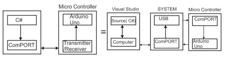
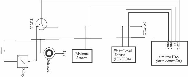
Figure 11: Hardware Schematic Diagram
International Journal of Scientific & Engineering Research Volume 8, Issue 8, August-2017 1393 ISSN 2229-5518 IJSER © 2017 http://www.ijser.org
3.0: RESULTS AND DISCUSSIONS
In this paper, the tools used in developing the prototype and the developed systems are described. The system has one application which uses the database; the Windows application which is the Frontend application for user interaction. The Windows application is developed using C#, which is one of the development languages in .NET and is object oriented. Embedded C is also used to program the Arduino Uno Micro controller.
• SYSTEM IMPLEMENTATION
This is actual putting together of all it takes for the designed system to perform the function which it was designed for in order to solve the research problem, in this case to perform irrigation using a computer software and accompanied hardware.
• Hardware Implementation Hardware implementation design basically shows the relationship between components/systems used in the design of the entire system. This is represented succinctly with the use of a circuit diagram as shown in figure 11. The source code of the C#-based Software for Water Pumping (Irrigation) System is written in C#- to support the software while Arduino Microcontroller system program was written in Embedded C. The results obtained from the software are presented in form of screenshot, as shown in figure 12, 13, 14 and 15. The system requirements for the development of the C#-based software include the following:
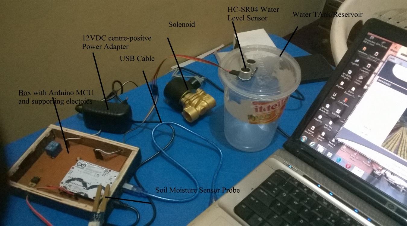
Processor: is any Intel® or AMD x86 processor supporting the SSE2 instruction set. An Arduino Uno Microcontroller with specification as shown in figure 3 with associated internal components such as a relay, resistor, etc Solenoid valve
Centre-Positive 12VDC power adapter
USB cable
Water Level Sensor (HC-SR04)
Probe-type Soil moisture content sensor
Wiring cables
• Software
Operating System: Windows OS Windows supported are Windows XP Service Pack 3, Windows Server 2003 R2 with Service Pack 2, Windows Vista™ Service Pack 1 or 2, Windows Server 2008 Service Pack 2 or R2, Windows 7 and Windows 8 Application: Microsoft Visual Studio 2008, Arduino Microcontroller Programmer.
IJSER
• Software Implementation
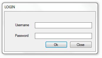
Here, the implemented system is described. How the user interacts with the system and some of the results of interaction with the system along with the screen shots are described. When a user starts the application, a login screen is displayed as shown in Figure 12 to authenticate the user. If the user has typed the correct user id and password to the login screen, the system displays a splash screen for 6 seconds and then a window containing the main menus of the system as shown in Figure 14 and the main window displays menus of the software. The system data log which serves as reporting platform is as shown in Figure 15
• Hardware:
A computer system with the following minimum specifications: Hard disk free space: 3-4 GB for a typical installation
RAM: 1024MB (at least 2048 MB recommended)
SYSTEM TESTING
System testing of software or hardware is a process conducted on a complete, integrated system to evaluate the system's compliance with its specified requirements and it fall within the scope of the project. It helps to detect any inconsistencies between the software/hardware units that are integrated
International Journal of Scientific & Engineering Research Volume 8, Issue 8, August-2017 1394 ISSN 2229-5518 IJSER © 2017 http://www.ijser.org
together. The Login, Software splash screen, the Main window and Data Reader (Data Log Viewer) are shown in Figures 13, 14, 15 and 16 respectively.
Figure 13: Software Splash Screen
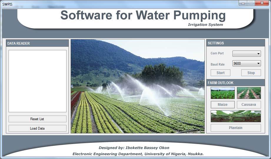

Figure 12: Login Screen
IJSER
International Journal of Scientific & Engineering Research Volume 8, Issue 8, August-2017 1395 ISSN
IJSER © 2017 http://www.ijser.org
2229-5518
Figure 14: The main window displays menus of the software
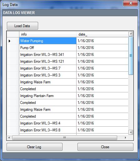
Figure 15: The Data Log Viewer/Result
•
SYSTEM DOCUMENTATION
System documentation is written text that accompanies systems which could be computer software, hardware or both. It either explains how it operates or how to use it, or may mean different things to people in different roles.
• User Manual
This is a brief of the operation of the developed system. Its features functions and usage. The “box” which contains the Microcontroller and it associated electronic is connected to a computer system which has finished booting the Software for Water Pumping (Irrigation) System [SWPIS] loaded through any of the computer’s USB ports. This is done after making sure the associated sensors are connected (attached) to where they should be – Soil moisture Content sensor probe to any soil/soil sample, Water level sensor to the storage tank/water reservoir (the Water level sensor should be at the top of the tank/reservoir NOT in contact with water but at least 5cm from the water surface). The solenoid should also be connected to the preferred distribution system (pipe network for irrigating a
particular farm or field) through a 1/2” pipe. The 12V-centre positive power supply should also be connected to any electrical socket outlet.
When the “box” is connected to the computer system through its USB interface, the computer automatically detects the external hardware and assigns it a ComPort. The User does not need to choose the Baud rate, the system automatically chooses 9600. The user then clicks on START to enable/establish/authenticate the connection between the microcontroller and the computer system. The User now choose the farm to be irrigated by clicking on the appropriate button- Maize, Cassava or Plantain…the name NOT the picture of the farm. When the User clicks on any of these, the system checks the conditions which are basically two.
1. Is there water in the reservoir (above the set threshold)?
2. Is the soil moisture content to the selected field as indicated in Table 3.1?
If these conditions are met, the farm will be irrigated for a pre-set period. The timing is pre-set to avoid user entering wrong values
International Journal of Scientific & Engineering Research Volume 8, Issue 8, August-2017 1396 ISSN 2229-5518 IJSER © 2017 http://www.ijser.org
IJSER
which may lead to under/over supply of water to the farm.
Error Reporting: If there is any abnormally – that is any of the above condition or any other abnormally that may affect the system adversely; the system will not pump/irrigate the farm/field. It will display such error in the DATA READER field of the software. WL error indicates Water level below threshold while MS error indicates soil Moisture Sensor indicating that the soil water content for a particular field or crop is already above the threshold – the crop(s) is already well watered and does not need irrigation at the moment. This was done to eliminate the use of RAIN Sensor which would have added to the cost of this project. It helps prevent the field from being watered after or during rain thereby saving water budget and protecting crops from being over-watered through water logging which can lead to wilting of the crops.
The DATA READER window also acts as a report display screen for the system log which shows errors, irrigation dates, etc. The Load Data Button loads the irrigation log while the Reset List clears the Data Reader workspace/window. After the fields are irrigated, the user clicks the STOP button to terminate the port communication, may disconnect the USB cord/external hardware box and continue to use the computer system for other purposes. At any other time irrigation is needed, the above processes ensue but the computer will
remember the ComPort that was used previously and reassigns it and the process continues.
The Data Log viewer/Result is a window that shows the working of the system (simulation to check if the system will perform as designed). It is used for system auditing and evaluation. WL-Water Level, MS-Moisture Sensor. Values MS3, MS7, MS121 and MS 341 indicate soil moisture content for different crops. MS3 means the soil is dry MS7 indicates the threshold for irrigating maize farm
MS121 indicates the minimum for irrigating cassava farm MS 341 indicates the minimum for irrigating plantain farm.
COMPLETED- indicates that the pumping or irrigation process was successfully done (the soil moisture content reads above the threshold).
IJSER
IRRIGATING MAIZE or PLANTAIN FARM indicates the farm being irrigated while 1/16/2016(date) provides the “time stamp” which is used to know when which activity took place.
For the pump (irrigate any farm) ALL parameters must be okay. (It will irrigate maize farm if WL is above threshold, MS reads below MS121; cassava farm if WL is above threshold, MS is below 341; Plantain farm if WL is above threshold and MS above 341, ELSE it will report “Error”.
International Journal of Scientific & Engineering Research Volume 8, Issue 8, August-2017 1397 ISSN 2229-5518 IJSER © 2017 http://www.ijser.org
4.0.
CONCLUSION
In this paper, an automated irrigation system that facilitates various activities that take place in farms was developed. The system developed in the paper consists of windows and hardware (micro controller) applications. These are two different applications on the same database. The windows application takes most of the activities such as logging, timing, Error reporting and activating the pumps. The Micro controller application facilitates the communication between the field sensors and the Windows software and the activation of the solenoid (pumping). The solution to the Irrigation Software is simple. The Water Level Sensor senses the level of water in the reservoir, the soil moisture content sensor senses the moisture content levels in the field these are compared with set values, if all set conditions were met, the pump solenoid will be triggered through a relay. If there were discrepancies the error will be logged so also are the time and field the irrigation took place will be dissipated. That information will be recorded and stored in the database.
IJSER
The prototype has been tested. It has been shown that the system effectively irrigate farms (fields), easily retrieves information about farms irrigated and generates the required reports such as error logs, date and time of irrigation. This finally saves human time and makes farming encouraging.
REFERENCES
[1] K. A. Ali, “Development of Water Supply Infrastructure in Nigeria: Challenges and Prospects,” 2012.
[2] Nyangasi, “Water pumping system design.” pp. 1–15, 2012.
[3] B. J. C. P. et Al, “Computer software tool REALM for sustainable water allocation and management,” Environ. Manage., pp. 291–300, 2005.
[4] “Irrigation the free encyclopedia, modified on 2 July 2015,” Https://en.wikipedia.org/irrigation, 2015. .
[5] A. M. Sirisha Adamala, N.S. Raghuwanshi, “Development of Surface Irrigation Systems Design and Evaluation Software (SIDES),”
International Journal of Scientific & Engineering Research Volume 8, Issue 8, August-2017 1398 ISSN 2229-5518 IJSER © 2017 http://www.ijser.org
Figure 16: Picture of the system setup with the software running
Agric. Food Eng. Dep. Indian Inst. Technol. Kharagpur, West Bengal 721 302, India, p. 721.
[6] Hassan A. Saliu, “Perspectives on Nation-Building and Development in Nigeria: Environmental and Economic issues - irrigation and Food Security.,” Fac. Bus. Soc. Sci. Univ. llorin, Niger., pp. 21–30, 2008.
[7] “C#,” Wikipedia, the free encyclopedia.htm. .
[8] Arduino Uno Datasheet
[9] “AMSi Solenoid Valve Datasheet,”
www. . [10] “Soil moisture sensor,” Wikipedia, the free encyclopedia.htm. . [11] “Grove_Moisture_Sensor,” www.seeedstudio.com. . [12] “water-requirements,” www.aboutcivil.org. . [13] “HC-SR04 Datasheet.” . [14] Degif Teka, “School Management System Addis Ababa University,” Sch. Grad. Stud. Fac. Informatics, Dep. Comput. Sci., 2008.
IJSER
International Journal of Scientific & Engineering Research Volume 8, Issue 8, August-2017 1399 ISSN
2229-5518
IJSER © 2017 http://www.ijser.org