
www.idosr.org
©IDOSR Publication
International Digital Organization for Scientific Research
IDOSR JOURNAL OF SCIENCE AND TECHNOLOGY 9(1):107-119, 2023.
ISSN:2579-079X
Design and Implementation of an Improved Automatic DC Motor Speed Control Systems Using Microcontroller
1Enerst Edozie, 2Eze Val Hyginus Udoka, 1Wantimba Janat
1Department of Electrical Engineering, Kampala international University, Uganda
2Department of Publication and Extension, Kampala International University, Uganda
ABSTRACT
Energy wastage is one of the major challenges that is facing the world now as there is insufficient supply of energy and the little ones supplied was not appropriately used. This energy wastage has made many researchers to engage more on the research to stop this energy waste as a result of inappropriate allocation of energy to some devices even when they don’t need it. This research work was able to design and implement an improved automated DC Motor speed controller system using microcontroller successfully. The software used for this research work were Fritzing software and Arduino Nano. This project was able to improve on the working system of the DC Motors and energy was automatically and successfully saved. The system runs entirely on Bluetooth technology which consumes less power than other devices. The Android application is user-friendly with enhanced Wirelesscommunication.Thisdesign wassuccessfully developedandimplemented with80% accuracy. The design was able to work effectively by increasing the cutting speed when the softness of the material decreases and as the cutting tool material becomes stronger, the cutting speed increases. This showed that the design is effectively and efficiently developed with less energy/power consumption which is the earnest desire of an Engineer as it reduces cost.
Keywords: Microcontroller, Improved Automatic DC Motor, Energy, Arduino, PWM
INTRODUCTION
Most of the industrial process requires to be run on the certain parameters since almost all the industries require motors in their operation to either increases or decrease the speed of the machine. Speed control of dc motor could be achieved using various mechanical or electrical techniques but this research project will basically focus on Pulse with Modulation (PWM) technique. Pulse with modulation is a modulation technique that generates variable pulses width to represent the amplitude of an analog input signal. By using pulse with modulation (PWM) technique, it is easy to control the average power delivered to a load and hence made it easy to control the speed of the DC motor. Pulse width modulation control works by switching the power supplied to the motor on and off very rapidly and the DC voltage is converted to a square wave signal, alternating between full (nearly
12v) and zero, giving the motor a series of power “kicks”. Pulse width modulation techniquesisatechniqueforspeedcontrol which can overcome the problem of poor starting performance of a motor [1][2][3][4][5]
The electric drive systems used in many industrial applications require higher performance, reliability and variable speed. The speed control of DC motor is important in applications where precision and protection are of importance. DC Motors are used in many systems in our day to day life which include running cranes, lifts, hair drier, electric footing, vacuum cleaner and in speed regulation applications such as wiper. DC motor is an electric motor that runs on direct current power. It works on the fact that a currentcarrying conductor placed in a magnetic field experiences a force that causes it to rotate with respect to its original
www.idosr.org
position. Practical DC Motor consists of fieldwindingstoprovidethemagneticflux and armature which acts as the conductor. The input of a brushless DC motor is current/voltage and its output is torque [6][7][8][9][10][4].
Furthermore, the challenge of controlling speed of motors used by different machines to a desired speed level required by the machine is always paramount to avoid wastage of energy. This problem of machines not been rated according to the required energy consumption which made the DC motor to be running at high speed while it needs to be operating at low speed has led to high energy or power consumption [2][1] [13] [14].
From the extensive review, it was observed that many others have never considered the problem of wastage of energy as many DC motors in machine were designed to be consuming energy more than required as there is no auto-regulator embedded on it.
Edozie et al
This research work will solve the problem ofinappropriateallocationofDCmotorsin a machine without auto-control system. This research work will showcase the best waytocontrolthespeedof DCMotorusing Pulse Width Modulation (PWM) technique coupled with android mobile phone Bluetooth applications. Smart phones have in-built Bluetooth technology which an external Bluetooth module and Arduino Uno microcontroller will be interfaced themforeasycommunication[15][16][17] [18] [19] [20]. The Bluetooth module receives command from the android mobile phone through the help of Arduino whereas MOSFET can be used to vary the voltage as well as the speed of the DC motor using PWM technique. The main objective of this research paper is to Design and Implement an Improved Automatic DC Motor Speed Control Systems Using Microcontroller that will be conservative in saving power/energy.
METHODOLOGY
This system was designed based on the following sequential methods:
i. The system was designed using the Fritzing software which is a circuit design simulation software
ii. A circuit board was used to connect the different electronic components following the circuit design that was done using Fritzing software.
iii. Microcontroller was programmed using Arduino Uno/C++ software language with a computer.
iv. A Control Panel interface was made using Bluetooth software and an android phone was used to connect to the Bluetooth
Module first and then thecontrol panel will be used to run the entire system. This means that the Control Panel is able to switch the system ON or OFF and also control the speed.
System design
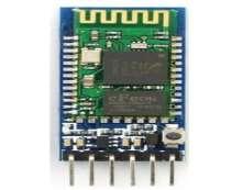
The system design of the proposed system uses two architecture designs which involve the power supply, input stage, control stage and output stage. This setup consists of two basic primary elements communicating Bluetooth devices such as (i) Bluetooth of smartphone which is connected to the Arduino microcontroller, and DC Motor interfaced with a switch and (ii) a Bluetooth module HC-05. Figure 1 is the systematic block diagram of energy flow in the designed system.
Power supply
Android App sends Data packets
Bluetooth module receives these data packets
Bluetooth Module
ARDUINONANO (Microcontroller)
Sends signals to DC Motor as per the value of data packets
Bluetooth serial communication module is one of the input device in this project design and it has two work modes: orderresponse work mode and automatic connectionworkmode.Andtherearethree work roles at the automatic connection work mode. When the module is at the automatic connection work mode, it will follow the default way set lastly to
DCMotor


transmit the data automatically. When the module is at the order response work mode, user can send the AT command to the module to set the control parameters and sent control order. The work mode of this Module can be switched by controlling the module PIN (PIO11) input level. In this project Bluetooth module is used to send signals from the Arduino Uno.
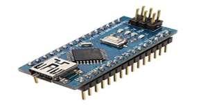
Arduino Nano is one of the controller in this research design on 8-bit ATmega328P microcontroller. It also consists of other components such as crystal oscillator, serial communication, voltage regulator, etc. to support the microcontroller. Arduino Nano has 14 digital input/output
pins (out of which 6 can be used as PWM outputs), 8 analog input pins, a USB connection, A Power barrel jack, an ICSP header and a reset button. The ATmega328P microcontroller provides UART TTL (5V) serial communication
www.idosr.org Edozie et al
which can be done using digital pin 0 (Rx) and digital pin 1 (Tx).
Android Phone: Android phone was used as an input which contains the Control Panel that will be used to control the system.
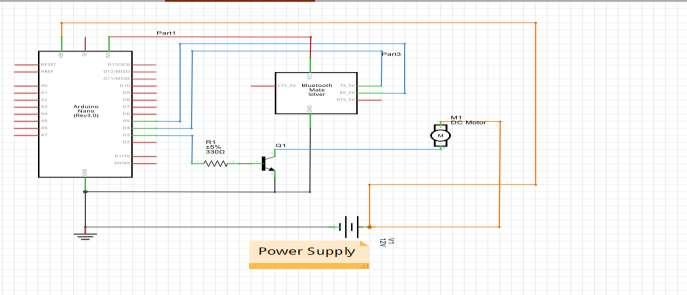
Designing steps 1: The components of the system have been connected as shown in the circuit diagram of figure 4
www.idosr.org
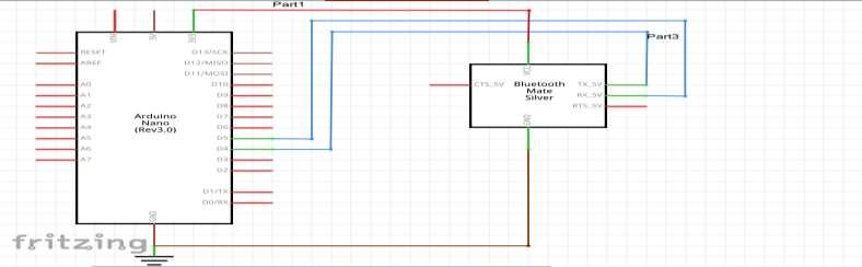
The system has been designed by Fritzing software since it is among the best latest ofcircuitdesignsoftwareandcorporateall of the devices used to come up with the prototype. Figure 4 is a simple illustration of how the system was implemented and the various components that’s made up the system.
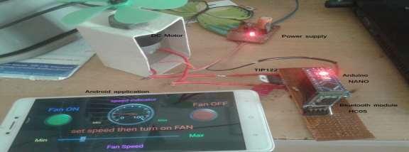
Step 1b: The connection of the Arduino and Bluetooth module: Thiscircuitisbuilt
using only three components: Arduino NANO, the Bluetooth module HC05, and a Darlington transistor TIP122. The HC05 has four interfacing pins: Vcc, GND, Tx, and Rx. Here, the Vcc pin is given a 5-V supply from the Arduino board and the GND pin is connected with the board’s ground. The Tx and Rx pins are connected with Arduino’s pins D4 and D5, respectively.
The circuit connections were followed belowtobuildtheSystem.ThePWMoutput pin D3 drives the 12-V DC motor using the TIP122. It’s connected to TIP122’s base terminal through the current limiting 330ohm resistor. The TIP122 is used to
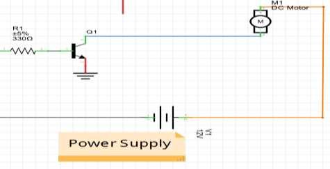
amplify the current, providing the required current to the motor. The DC motor is connected between the collector output and the 12-V supply. The TIP122’s emitter terminal is connected to the ground.
www.idosr.org Edozie
Circuit operation: The circuit controls the speed of the 12-V DC motor using the Android app on a smartphone. The app sends the commands to start or stop the motor and to change the speed of the motor via the smartphone’s Bluetooth. These commandsare received by the HC05 module, which passes them on to the Arduino NANO via the Tx and Rx pins. As per the commands sent over, Arduino will run or stop the DC motor, or vary its speed from minimum to maximum. Arduino generatesa PWMsignalonits D3pintorun or stop the motor or to vary the motor speed. To stop the motor, the pulse width
on the pin D3 is 0 (0%). And to run the motor at full speed, it’s 255 (100%). So, as Arduino changes the pulse width on its D3 pin, the motor speed changes from min to max orviceversa.Arduinocanalsosend a change in motor speed (0 to 100 %) from the HC05 module to the smartphone’s app. The Android app will then display this motor speed value on an analog dial (or speed dial).
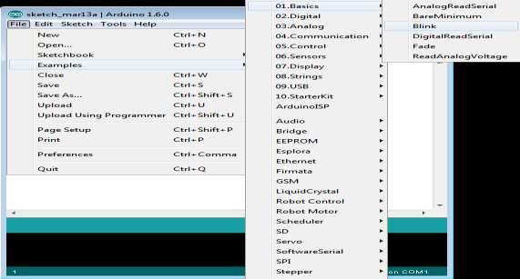
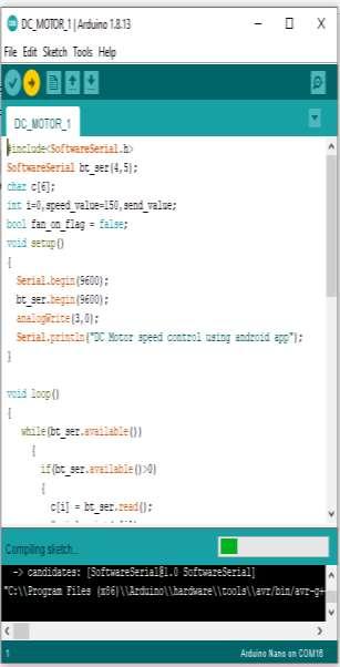
Step 2: Launch the “blink program” to test the board status: Open your Arduino software from your computer and follow the steps as shown in the figure 7
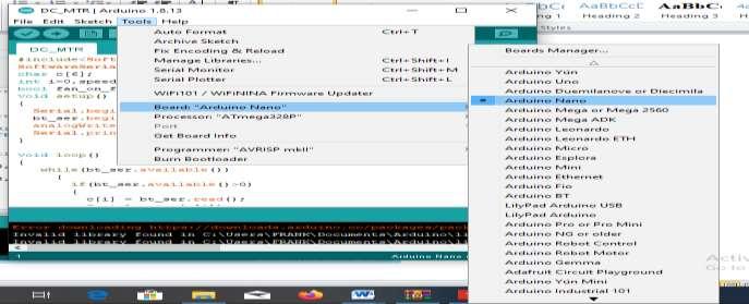
Step 3: Select the Arduino Nano Board type
#include<SoftwareSerial.h>
SoftwareSerial bt_ser(4,5); char c[6]; int i=0, speed_value=150,send_value; bool fan_on_flag = false; void setup()
{ Serial.begin(9600); bt_ser.begin(9600); analogWrite(3,0);
Serial.println(“DC Motor speed control using android app”); }
void loop()
{ while(bt_ser.available())
{
if(bt_ser.available()>0)
{ c[i] = bt_ser.read();
Serial.print(c[i]);
i++;
}
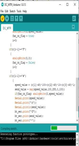
if(c[i-1]==’N’)
{ analogWrite(3,speed_value); fan_on_flag = true; i=0;
}
if(c[i-1]==’F’)
{ analogWrite(3,0);
fan_on_flag = false; i=0;
www.idosr.org
if(c[i-1]==’#’)
speed_value = (c[1]-48)*100+(c[2]-48)*10+(c[3]-48)*1; send_value = map(speed_value,100,255,0,100); if(fan_on_flag) analogWrite(3,speed_value); Serial.print(speed_value); Serial.print(‘\t’); Serial.println(send_value);
bt_ser.print(“*D”);
bt_ser.print(send_value); bt_ser.print(‘*’); i=0;
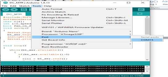
Step 5: Select serial COM port: Connect the Arduino NANO to the computer’s USB port using a using a USB cable and then
select the Serial COM port to be used. For example, in the illustration figure 10 serial COM port 15 was selected.
Step 6: Build the Android app or Panel: The Android application is built using the “Bluetooth Electronics” application, which is available for free on Google Play. First, download and install the “Bluetooth Electronics” app on your Android phone and open it. It will ask if you want to turn “ON” the device’s Bluetooth. Allow it to do so. Once the app starts, you’ll see a few readymade control panels that control Arduino-based projects. Perhaps the most interesting feature of this app. It also allows the users to build a customized panel to control Arduino projects. The Arduino panel that controls the app is built as show below: The panel consists of a green and red button to turn the mother “ON” or “OFF.” It also has one slider to vary the motor speedand onedial to view the motor speed.
1. Select one green button. Then, go to the right corner of the screen and edit the button properties as follows:
Press Text: N
Release Text:
2. Choose the text size with either a small or medium font, and write “Motor ON.”
3. Select one red button and edit its properties as follows:
Press Text: F
Release Text:
4. Choose the text size with either a small or medium font, and write “Motor OFF.”
5. Select the biggest slider from the slider options and edit its properties as follows:
Min Value: 100
Max value: 255
Select “Send on slider change”
String starts with: *
String Ends with: #
6. Go to the indicator options and choose theanalogdial. Editits propertieslikethis:
Receive character: D
Min Text: 0
Max Text: 100
min value: 0
max value: 100 leave default all others
7.Write all of the other text,suchas “min”, “max”, “motor speed”, “speed indicator” etc., as you choose.
And that’s it! Your android app is ready to control the DC motor speed. Running the project
www.idosr.org
1. Connect the circuit as per the given schematic on the bread board or on the general purpose PCB.
2. Give the 12-V power supply to the circuit.
3. Initially, the motor is not moving and is in the stop position. The HC05 module will start blinking to indicate it’s searching for the device.
4. Start the “Bluetooth electronics” application in your smartphone, ensuring the Bluetooth is “ON.”
5. Press the connect button so it searches for the HC05 module. When the device is
found, select “HC05” and press connect. When doing so for this first time, you’ll have to enter passkey “1234.”
6.OncetheHC05isconnected,pressdone.
7. Now, you can run your panel.
8. From the panel, press the green button to start the motor or the red button to stop it.
9. While the motor is running, change the slider to vary the motor speed.
10. As the slider moves, the speed dial will indicate the motor speed (from 0 to 100%).
Table 2: Description of Methodology
Objective Method Description / purpose
Types
Factories and industries will be visited randomly for an interview schedule aimed at getting the following data; to know the different motors in their factories and industries. The purpose of this exercise is to know the advantages and disadvantages of different types of motors in those factories and industries and also to know problems associated with different motors in different factories and industries.
Methods speed control of motors.
Engineers from different factories and industries will be interviewed about the different methods the employ in controlling the speed of motors in these different factories and industries. The purpose of this is to know the challenges these factories and industries face during speed control of motors.
PWM technique -Library and internet search
The university academic library and the internet sites will be visited to obtain the following; relevant engineering text books to discover the right information required upon the pulse width modulation. The purpose of this research will help in material selection to be used.
Thehardwareassembly ofthe components as diagram of the circuit was as shown in figure 12, this showed the sequential flow of the programs in the system.
RESULTS
This designed system has to undergo testing which will require running the system using the Control Panel of the phone which should be able to switch the
system ON or OFF and vary the speed of the DC Motor from Minimum to Maximum speeds.
6.
Table 4 showed the cutting speed (usually in feet per minute) of a tool when it is cutting the work. It is observed from table 4 that as the softness of the material decreases, the cutting speed increases and
as the cutting tool material becomes stronger, the cutting speed increases. This showed that the design is effective and efficient and as well conserves energy and power usage.
Table 4 showed the cutting rotation speed of an electrical machine in radian per minute. It was observed from table 4 that
all ultra-high-speed materials were operated on jointly with power electronics and control systems. This obviously safes
www.idosr.org
energy and power the rotation speed is relative to the material it is operating on whereas same material observes the same speed.
Summary of the findings
The testing is done in stages, this helped to identify the current and voltage flow in
Edozie et al
the circuit. It was done in different intervals to confirm the current and voltageinthecircuits.Theresultsfromthe tests done, confirmed that the design and implementation of thesystem is doingexactly what it was designed for and therfore the deisgn was succesful.
CONCLUSION
Energy consumption is increasingly becoming high over time, which is becoming costly because of no speed control measures. This project was able to improve on the working system of the Motors which shall be used to run the machines using an automated control system which saves energy and power from being wasted. The system runs entirely on Bluetooth technology which consumes less power than other devices. The Android application is user-friendly
with enhanced Wireless communication. This design was successfully developed and implemented with 80% accuracy. The design was able to work effectively by increasing the cutting speed when the softness of the material decreases and as the cutting tool material becomes stronger, the cutting speed increases. This showed that the design is effective and efficient and as well conserves energy and power usage which is the earnest desire of an Engineer as it reduces cost
REFERENCES
[1]. Reston Condit, Idaho (2004). Reston Condit Microchip Technology Inc., Brushed DC motor fundamentals
[2]. Eze,M.C.,Eze,V.H.U., Chidebelu,N. O., Ugwu, S. A., Odo, J. I. and Odi, J. I. (2017). NOVEL PASSIVE NEGATIVE AND POSITIVE CLAMPER CIRCUITS DESIGN FOR ELECTRONIC SYSTEMS. International Journal of Scientific & Engineering Research, vol. 8, no. 5, pp. 856–867
[3]. V. H. U. Eze, S. C. Olisa, M. C. Eze, B O. Ibokette, and S. A. Ugwu, (2016). EFFECT OF INPUT CURRENT AND THE RECEIVER-TRANSMITTER DISTANCE ON THE VOLTAGE DETECTED BY INFRARED RECEIVER, International Journal of Scientific & Engineering Research, vol. 7, no. 10, pp. 642–645
[4]. Sitompul, E. and Bukhori, I. (2021). A new approach in self-generation of fuzzy logic controller by means of genetic algorithm. IEEE 6th International Conference on Information
[5]. Enyi, V. S., Eze, V. H. U., Ugwu, F. C. and Ogbonna, C. C. (2021). Path Loss Model Predictions for Different Gsm Networks in the University of Nigeria , Nsukka Campus Environment for Estimation of Propagation Loss. International Journal of Advanced
Research in Computer and CommunicationEngineering, vol. 10, no. 8, pp. 108–115. doi: 10.17148/IJARCCE.2021.10816.
[6]. Eze, H. U., Eze, M. C., Chidiebere, C. S., Ibokette, B. O., Ani, M. and Anike, U. P. (2016). Review of the Effects of Standard Deviation on Time and Frequency Response of Gaussian Filter. International Journal of Scientific & Engineering Research, vol. 7, no. 9, pp. 747–751
[7]. Piscataway, N J (2014). Technology and Electrical Engineering (Institute of Electrical and Electronics Engineers pp. 1–6
[8]. Enerst, E., Eze, V. H. U., Musiimenta, I. and Wantimba, J. (2023). Design and Implementation of a Smart Surveillance Secuirty System, IDOSR Journal of Science and Technology, vol. 9, no. 1, pp. 98–106, doi: 10.5120/cae2020652855.
[9]. Siong, T. C., Ismail, B., Siraj, S. F., Mohammed, M.F.and Tajuddin, M.F. N. (2010). Implementation of fuzzy logic controller for permanent magnet brushless DC motor drives
IEEE International Conference on Power and Energy (Institute of Electrical and Electronics Engineers, Piscataway, NJ, pp. 462–467
www.idosr.org Edozie et al
[10]. Eze, V. H. U., Onyia, M. O., Odo, J. I. and Ugwu, S. A. (2017). DEVELOPMENT OF ADUINO BASED SOFTWARE FOR WATER PUMPING IRRIGATION SYSTEM, International Journal of Scientific & Engineering Research, vol. 8, no. 8, pp. 1384–1399.
[11]. Adabara, I., Anthony, K. M., Arban, M., Stephen, O., Okoth, G. O., Edozie, E. and Nasser, M. A. (2021). Design and Analysis of a Substation Digital Control System.
[12]. Enerst, E., Eze, V. H. U., Ibrahim, M. J. and Bwire, I. (2023). Automated Hybrid Smart Door Control System,” IAA Journal of Scientific Research, vol. 10, no. 1, pp. 36–48
[13]. Edozie, E. and Vilaka, K. (2020). Design and Implementation of a Smart Sensor and RFID Door Lock Security System with Email Notification. InternationalJournalof EngineeringandInformationSystems (IJEAIS), 4(7), 25-28.
[14]. Ogbonna, C. C., Eze, V. H. U., Ikechuwu,E. S., Okafor, O.,Anichebe, O. C. and Oparaku, O. U. (2023). A Comprehensive Review of Artificial Neural Network Techniques Used for Smart Meter-Embedded forecasting System. IDOSR Journal of Applied Science, vol. 8, no. 1, pp. 13–24
[15]. Kalyankolo, U., Kigenyi, A., Kavuma, L., Isabirye, W., Edozie, E. and
Kalyankolo, Z. (2021). Design and Implementation of Three Phase PWM Inverter Control Using Microcontroller. International Journal of Engineering and Information Systems, 3 (2): 21-32.
[16]. Umaru, E. K., Edwin, A. and Edozie, E. (2021). Design and Implementation of an Automated Self-Cleaning Solar Panel using Microcontroller. International Journal of Engineering andInformationSystems,5,1,pp2226.
[17]. Kalyankolo, U., Aguto, A. G., Kalyankolo, Z. and Edozie, E. (2021). Design and Implementation of an Android Based Automatic Phase Selector and Overload Protector Using GSM. International Journal of Academic Engineering Research, Vol. 5 Issue 1, pp 1-5
[18]. Adabara, I., Stephen, O., Okoth, G. O., Cyril, A. O. and Edozie, E. (2019). Implementation Analysis of Automatic Dual Axis Solar Tracking System Using Atmega328p International Journal of Academic Engineering Research. https://kiu.ac.ug/publicationpage.php?i=implementationanalysis-of-automatic-dual-axissolar-tracking-system-usingatmega328p