Comprehensive Review of Recent Electric Vehicle Charging Stations
Val Hyginus U. Eze1,4, Martin C. Eze1 , Chibuzo C. Ogbonna1, Samuel A. Ugwu1, Emeka K. Ogbonna2, Christian A. Onyeke3
1Department of Electronic Engineering, University of Nigeria, Nsukka 2Department of Agric Education, University of Nigeria, Nsukka
3Centre for Lion Gadgets and Technologies, University of Nigeria, Nsukka
4Department of Computer Science, University of Yaoundé 1
Abstract The uncertainty associated with modelling and performance of Electric Vehicle (EV) design could be easily and efficiently reduced by using hybridized renewable energy sources. During the past decade the struggle for effective utilization of EVs was very high due to its unreliability interns of durability and sources of charge. This review classified charge station into renewable, nonrenewable and hybrid based on its sources of power generation. In addition, for this decade there is no extensive and comprehensive review on applicability of renewable, non-renewable and hybrid models for performance prediction and modelling of EVs. Therefore, this article focuses on extensive review of design, modelling, battery backup, battery durability, Efficiency Enhancement (EE) components and connectors, advantages and disadvantages of each design based on renewable, non-renewable and hybrid EV charge stations. Furthermore, a total of 15 selected recent articles on the EV charge station together with its technology were reviewed. The review showed the suitability and reliability of renewable, non-renewable, and hybridized EV charge stations. It also showed that hybridization of renewable energy sources with suitable EE components and connectors gave the best EV design in terms of fast charging, priority scheduling and excellent battery backup. Finally, this review presents guide for researchers and engineers in the field of EVs in selecting the best and suitable design to adopt when designing EV charge stations.
Keywords Battery Backup, Charge Station, Electric Vehicle, Renewable Energy, Solar PhotovoltaicI. INTRODUCTION
The economic development of a nation, urbanization and industrialization strongly depends on fossil fuels as sources of energy for mobility and electricity generation. The increase in population, industrialization and urbanization has led to increase in fossil fuel vehicles. In the pursuit to make-endsmeet, people travel from one place to another using fossil combustion vehicles as means of transportation which implicatively causes air pollution and ozone layer degradation. The released CO2from the exhaust of combustion vehicles is harmful to the health and also causes global warming. These mentioned pitfalls of fossil fuel in the area transportation attracted the attention of government which made them to lay down some policies that encouraged both the users and producers of Electric Vehicles (EV). This policy led to an increase in EV production and usage which became a treat to the nonrenewable energy sector such as fossil fuel and grid due to high electricity demand by the EV users. This huge consumption of energy by the EVs became a problem as it reduces the quantity/amount of energy that was channeled to other energy consuming sources such as households, industries etc. Furthermore, one of the efficient ways to overcome the impact of this high electricity demand by the EVs from the grid is by decentralizing the power generation and integrating renewable energy as a source for charging EVs. Among all the renewable energy sources such as thermal, wind, and biomass, solar photovoltaic has proven to be the best alternative means to compliment the quantity of energy in use due to its unique characteristics. The unique characteristics of solar Photovoltaic (PV) that made it to have
advantage over other renewable energy sources are; its natural occurrence, user friendly and low maintenance cost. Another good reasons why solar PV system is preferably used as an alternative source of energy for EV charging is because the demand for EV charging is always high in the daytime which is always the global power peak of PV. Apart from using EV as harmless, efficient and effective means of transportation and the use of solar PV systems as an alternative renewable source of energy to compliment the nonrenewable sources, it also has the problem of environmental, geographical and technological factors. For the PV system to deliver at its optimum, some of the mentioned factors has to be considered for effective installation and delivery to the load [1][2][3].
The efficiency and performance of solar PV module depends on factors such as: geographical factors (latitude, longitude and irradiation), Environmental factors (pollution, humidity, wind, temperature, Dust and rain) and Photovoltaic technology (crystalline, mono crystalline, polycrystalline and thin film). So, for PV solar energy to be efficiently and economically used, there is a need to study the environmental parameters that can negatively affect the performance of the PV system and to deploy the best method to minimize it. However, the solar modules are rated under Standard Test Conditions (STC) with irradiance of 1000W/m2, ambient temperatureof25˚CandAirMassof1.5 [4].
The five major environmental factors that affect the efficiency and performance of a solar Photovoltaic module are irradiance, humidity, temperature, wind and dust.
1.1 Operating Principles of Solar Photovoltaic cells
Val Hyginus U. Eze, Martin C. Eze, Chibuzo C. Ogbonna, Samuel A. Ugwu, Emeka K. Ogbonna, and Christian A. Onyeke, “Comprehensive Review of Recent Electric Vehicle Charging Stations,” Global Journal of Scientific and Research Publications (GJSRP), Volume 1, Issue 12, pp. 16-23, 2021

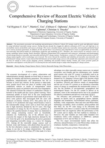
The photons of the solar irradiance shines on top of the cell and some photon rays reflected, some penetrated into the substrate while the rest with lesser energy passes through the cell without any impact. A pair of electron-hole can only be created by photon rays with energy level above band gap of silicon and the pairs of electron-hole were generated on both sides of the p-n junction. The metal contacts situated at both sides of the solar cell is responsible for collection of generated
current. The current was generated by using electric filed mechanism where the minority charges are diffused into the junction and were swept away in opposite direction in order to produce current [5] Figure 1 showed the basic operating principles of solar cell. Photovoltaic cells generate electricity from the sun whereas Solar panel converts sun light into electrical energy.
1: Working Principles of Photovoltaic Cells[6]
The current output of photovoltaic solar cells is simplified as in (1).
I=I_Ph-I_0 (e^(q(V+IR_S )/AnKT)-1)-(V+IR_S)/R_P (1) Where; I = current output of the PV cell; Iph = Current of the PV, Rp = shunt resistance of the cell Io = Saturated reversed current of the diode; K = Boltzmann’s constant (1.3805x〖10〗^(-23) J/K ) V = Output voltage of the PV cell; A = ideality factor; q = Electron charge (1.6x〖10〗^(-19 ) C)n = number of cells; T = temperature (k); Rs = series resistance of the cell[7]
II. TYPES OF ELECTRIC VEHICLES CHARGE STATIONS
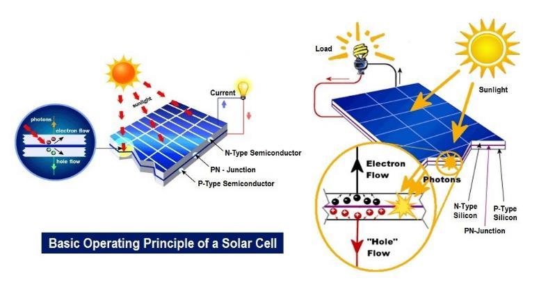
Electric Vehicle charging stations has been in existence since 1900 but its existence was not popular for decades because the advantage and economic importance has not been noticed by the government and public films. As from 2017 the advantages and its economic and health benefits was realized, and people started trooping into it. This made government and researchers to embark on serious research for its effective stay in the society by designing more effective and efficient charge stations to encourage the EV manufacturers and users. Figure 2 shows the trend of electric Vehicle station designs from 1900-2017.
Electric charging station is divided into grid-based EV charge station, Renewable based EV charge stations and hybrid EV charge stations. Each designed station has its prone and corns which delimits it to a particular function and operation. Among the three-charge station based, renewable takes the lead because of its natural occurrence, user friendly, low cost and almost free cost of maintenance.
Many researchers and designers have done a great work in the field of EV charging station in the quest to obtain the best EV charge station using the limited available power sources within their location. The EV charging stations designed by different researchers with different specifications and components are reviewed as follow: In [9], the author investigated the features, architectures, costs, infrastructures of solar PV standalone and grid connected EV charging station systems. This extensive review of the charge stations with respect their features and functions help the EV manufacturers to redesign their cars with respect to some certain specifications. The author details examined and elaborated on the three levels of EV charger known as level 1 which is 40KW, level 2 which is 80KW and level 3 is 240KW. The two charging stations to be discussed are PV grid charging station and the PV standalone charging station.
2.1 Hybrid Electric Vehicle Charge Stations
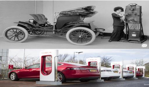
This is the type of EV station that combines both the renewable and nonrenewable sources of energy to power the electric vehicle charge stations. It also involved the combination of both two renewable sources to form a gigantic array that will produce steady state power to the EV station. Good example of grid connected EV station is as shown in figure 3. It is one of the effective means of providing steady power to the EV charge stations but has a lot of prone and corns.
The EV charging station architecture in figure 3 was a typical grid connected EV station with battery as backup. The
Issue 12, pp. 16-23, 2021
charge station is made up of two energy generational sources know as PV and grid and the third component is the backup. The charge station is made up of DC-DC and AC-DC
connection for effective power transfer. It was designed that battery as backup is optional as the backup can come from the grid.
Figure 3: Block Diagram of a PV-Grid Charging Station[10]
The authors investigated the convivial topologies for integrated PV-grid charger which is an added advantage. The disadvantage is that the battery backup (ESU) was waste of resources as the backup comes from the grid. Hence, excess power generated from the solar PV power during the peak hours is wasted as it is a grid unidirectional transfer.
The researcher in [11] developed a model for technical and economic comparison of different charging stations under different load conditions for effective utilization of EVs. An effective, easy, and friendly-excel-based tool which helps in planning and managing EV solar charging station was reviewed in this work. This particular model involved the hybridization of renewable and grid-based energy sources for the EV charge station design. Therefore, the effective design tool for this research report here is based on Excel. This excel tool can be expanded by incorporating many other efficient charging station tools. The station was designed to charge only five EVs at maximum charging load of 22 kW each with inverter capacity of 100kW. The paper reviewed possible ways of time scheduling and also analyzed the cost of PV systems characteristics and performance of PV modules with relevant PV characteristic equations.
The advantage of this reviewed work is that it estimated and determined cost of components that are used in designing EV charge stations. It also considered charging tools even though it didn’t make use of priority scheduling. The disadvantage of this model is that the designer did not put in consideration the fluctuation/oscillation in the power dissipated by the PV panels which automatically reduces the rated power of the PV. Secondly, the charging per EV will be costly because it is not purely renewable source as the power from the grid will be very high in price and will also cause energy shortage in the grid.
In [12], An off-grid and renewable energy source with battery back EV station was hybridized to improve the overall system’s efficiency and reliability. The objectives of designing this improved EV station were to (1) develop a standalone renewable energy-based EV fast-charging station consisting of (a) concentrated Photovoltaic (b) Thermal (CPV/T) (c) Wind turbine and (d) Biomass combustion systems. (2) Incorporate lithium-ion batteries, H2, NH3 and PCM in the design as
multiple sustainable energy storage. (3) Integrate Li–Br absorption cooling system to cool lithium-ion batteries. (4) thermodynamically analyze the developed EV charging station design and assess the technical feasibility of the overall system.
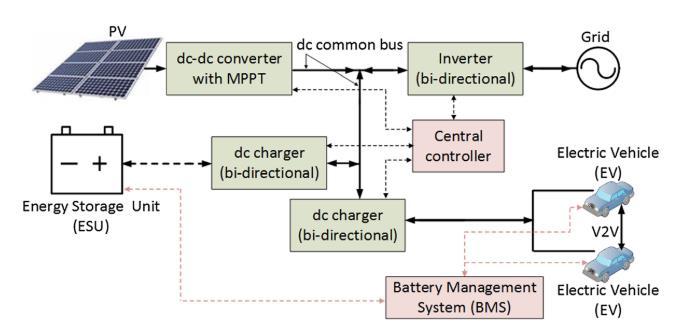
This hybridized three renewable sources of energy to ensure steady and sufficient power supply to the EV station. The design was complemented with three types of energy storage systems such as electrochemical, chemical, and thermal. These was used to design a reliable standalone fast-charging EV station with charging capacity of 80 EVs per day with an internal cooling system as shown in figure 4.
The advantage of this class of EV station is that it investigated the impacts of several significant operating parameters, such as battery capacity, solar irradiation, wind speed, and ambient temperature to find out the optimal configuration and its operational mode. Their disadvantages are complex circuitry, expensiveness and no priority scheduling.
2.2 Solar Photovoltaic Electric Vehicle Charge Stations
This is an EV charge stations that is made up of only renewable sources of energy like solar PV, wind turbine biogas etc in a non-combined form. Due to the disadvantage of power wastage found in grid connected PV charging station an off grid charging station was designed with some special features. The standalone PV or off-grid charging station can also provide sufficient energy to EV’s charging station using batteries as backup. This can provide sufficient energy to the station when all the necessary and important features and infrastructures are appropriately and careful installed.
This type of charging station is one of the best and most economical charging stations to adopt to avoid shortage of power from grid and to reduce cost per charge of EV. As far as solar PV charging station obtains its energy source from a natural gift of nature, the cost per EV charge is always cheaper when all the necessary infrastructures were installed for effective performance. The type of battery and the capacity of the battery to be used as backup is also an important factor to consider during PV charging station design.
1, Issue 12, pp. 16-23, 2021
In [9] the author concentrated in the design of charge controller and pointing out its major advantages. An algorithmic program for PV charge controller that regulates the potency of battery charging furthermore because the PV array consumption was developed during this reviewed paper. This is one of the solar PV based EV design charge stations. It also explained in detail the advantages and disadvantages of the two types of EV charging stations which comprised of

Photovoltaic Charging Stations (PVCS) and Grid charging stations (GCS). The design in this review has no backup and was not channeled to the grid which led to power wastage. The disadvantage of this type of solar EV charge station is the power wastage during PV peak time as no backup is incorporated on it. The station will not be reliable as there will be no steady-state energy supply to the charge station on cloudy days and in the night.
Figure 5: Block Diagram of Standalone PV Charging System
In [13], the author reviewed some possible solutions and existing techniques that has been in use and the best to be adopted. The author modelled single diode model inseries, shunts and combined series and shunt controllers using MATLAB Simulation. The charge controller was modelled using both constant voltage and current sources as regulator. Series and shunt charge controller were used in modelling constant current and voltage whereas in combined form shunt constant current is used. However, voltage and current flow between the panel and the battery is regulated by series charge controller. This also help in regulating charging and discharging of batteries which increases the life span of the

battery and enhances battery performance. Furthermore, voltage and current flow between the battery and the load was regulated by shunt charge controller. It also takes care of excess generated power thereby channeling it to designed gadget such as air conditioner without interruption to the load supply.
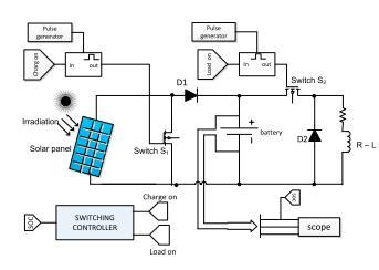
The circuit components and inter-switching mechanism of the EV designed model is as shown in figure 6. The difference between the series, shunt and combined charge controllers was just the series and parallel connections of the switching elements. The automatic functioning of switches, State Of Charge (SOC) of the battery was designed to be regulating the
, Volume 1, Issue 12, pp. 16-23, 2021
battery at 80% full charge. It was designed that S1 and S2 will trigger ON at a time when the battery SOC is 80%. Hence, the 2 switches ON and OFF at same time as load ON. When the switches are ON both the load and battery will start to be charging and when it is OFF the battery will start to be discharging there by charging the load.
number of switches which reduced cost. It was then deduced that this reviewed paper contained a concept for an optimized and safe battery charging system for home and other commercial systems by utilizing a direct connection between solar PV panel and battery system. With the help of this charge controller, user enjoyed the efficient and effective utilization of the solar PV and the extended lifetime of battery[13]. The drawback of this paper is that it did not put in consideration the solar PV specifications and secondly, locating EV charging stations in some strategic places for commercial use limits access to users. The author did not in any way consider charging priority, scheduling and MPPT
Figure 6: Charge Controller using MATLAB Simulink
The disadvantages of shunt charge controllers are: More power is loss at the panel side due to continuous current flow and it makes the PV module to heat up. The shunt charge controller is principally used for low power applications within the real time situation To overcome the demerits of the series and shunt charge controller, the combination of series and shunt charge controller is developed which combined the two features for effective delivery. This new feature showed the effectiveness of the designed controller with reduced

In [14] the author developed and designed a solar powered Electric Vehicle charging station which focused on the practical design and implementation of the charge station. The author presented practical design with the following features (1) universal input EV battery charger to be used in a plug-in hybrid vehicle (2) capable of maintaining a high-power factor at the front end and the low ripple current at the output (3) the implementation of Type-1 connector to control of the vehicle charging mechanism.
The metrological specifications of the solar PV EV charging station designed were as in table 1. This design was implemented in Indian at Aligarh with metrological location site of 78N, 27E.

TABLE 1: Average Hourly Data of Aligarh
Month Jan Feb Mar Apr May Jun Jul Aug Sept Oct Nov Dec Sunshine(hrs) 6.9 7.7 7.7 8.7 8.5 6.5 5.3 5.7 7.3 8.7 8.2 7.0
The system comprised of 6.4 kW solar PV-EV charging parking microgrid slots that is made up of 20 solar panels of Vikram Solar Company with each panel rating 320Wp, 37V. It has the capacity of charging 6 kW load per 8 hours. The PV electrical characteristics were calculated under standard change condition of 25°Ctemperature, 1000W/m2irradiance and air mass of 1.5. The Solar PV Charging Station at CARET, AMU in Indian is as shown in figure 7.
Figure 8: Vehicle Charging mechanism
Figures 7 and Figure 8 showed the typical PV array, components of the solar conversion system and EV charging station together with the power flow. The fluctuations and intermittency in a solar generation is regulated by the charge controller and battery storage respectively. The advantage of this designed station is that it has a steady power supply without power interruption. The disadvantage of this design is that it never considered transferring the excess generated power to the grid during the solar PV peak hours which leads to power wastage.
In [15], a standalone polycrystalline photovoltaic system at Lublin Science and Technology Park (LSTP) was used for this study as shown in figure 9. It consists of two micro installations of polycrystalline PV panel with a peak power output of 40 kWp each. The quantity of power generated by such gigantic polycrystalline PV system without being channeled to the grid will lead to power waste. Due to excess wastage the school decided to install EV charging stations
Volume 1, Issue 12, pp. 16-23, 2021
within the school vicinity to minimize the wastage of harnessed power from the PV.

charging stations and also more ways to improve the power extracted from that solar system.
III. ELECTRIC VEHICLES CHARGING ENCHANCEMENT DESIGN COMPONENTS
These are the most important components that are needed for effective and efficient energy supply to the EV station for fast charging. Some of the important charging technologies and standard components that made up the EV charge stations are; bidirectional DC charger, MPPT, Bidirectional Inverter, Energy storage system and station to vehicle connectors.
It was observed that each month in winter surplus electricity generated by the LSTP was found to range from 1.5 to 2.6 MWh. This excess energy generated from the gigantic solar energy installation was channeled to EV charging. The designer of the EV charging station designed an on-board three-phase EV charger with a maximum power of 22 kW to cater for the needs of Electric vehicles. The designer matched the power requirements of the on-board charger to correspond with the excess power generated by the PV system in one section of the school. In fact, they are not chargers, however electricity consumption points. On-board Type 2 connector was used to provide three-phase alternating current to the EVs with charge controller for monitoring charging. A technique to measure the amount of power consumed by EVs was also introduced for effective costing of consumed power per EV. Good example of such a device is the Wallbox as shown in Figure 10. It is described by the manufacturer as an intelligent, innovative semi-fast charger for 22 kW EVs. Charger management is one of the important applications in EV as it contributes to charging rate which also assists the user to manage energy consumption and other available features.
3.1 Bidirectional DC Charger
Bidirectional DC charger is one of the Efficiency Enhancement Designs (EED) that is used to enhance the power harnessed and transferred to the EV station for fast charging. The main function of a DC charger in a Solar Photovoltaic is to allow an effective control during the charging process by interfacing the DC bus voltage with the EV battery. The charge system for EV is classified into offboard and on-board types with uni or bi-directional power flow. The difference between the unidirectional and bidirectional power is that the bi-directional allows the flow of power in two directions, that is from the grid to the vehicle, battery to the vehicle and back to the grid while unidirectional DC charger allows the flow of power in one direction, and it limit its functions.
The advantage of bidirectional DC chargers is its compactness and higher reliability. The Bi-directional DC charger design is as shown in figure 11. The switches are used for controlling ON and OFF power flows from solar PV panel to battery and from battery to the EV and also from PV back to the grid. The disadvantage of bi-directional DC charger it is expensive due power transfer operation. It also needs an expert to design it in order to avoid surge in the grid as the grid must accept power transfer from the PV whenever it excess is generated.
This mini charge station proved that photovoltaic is capable of charging EVs comfortably when all the necessary measurements are being put in place. The advantage of this EV station is that it reviewed the important of charging cables and costing methods which other designs did not consider. Secondly, it also performed parameter measurements which will help ascertain how many EV that can be charged in a day, and it will also help in scheduling the EVs to be charged based on priority. The disadvantage of this EV charging station is that it never considered strategic location for siting the EV

Figure 11: Bi-directional DC Converter

3.2 Maximum Power Point Tracking (MPPT)
This is used to balance the impedance of the load with that of the solar PV panel for effective delivery. This is achieved by driving the impedance of the solar PV panel as close as possible to the impedance of the load. Furthermore, for maximum power to be transferred from the panel to the load the resultant conductance of the system must be zero and this can only be achieved by introducing MPPT into the charge controller of the EV charge station for effective harnessing.
12, pp. 16-23, 2021
3.3 Conductive Charging Technology
There are diversities of charging technology and various charging standards with respect to expected power and time taken for it to charge a device. Chargers are designed for fast and low charging depending on the mechanical make ups .The rating of charging and the charging standards according to International Electro technical Commission (IEC) is as shown in table 2 and the corresponding charging time formula is as shown in equation (2). To achieve fast charging time of EV battery, charger with sufficient power is needed to suit designers’specificationregardspriorityscheduling.
Table 2 Charging Time Standard by IEC61851-1[16]
Ordinary charging 1phase
Network connection
V=230VAC I=16A P=3.7kW
Ordinary charging 3phase Fast charging Extremely fast charging
V=400VAC I=32A P=22/43kW
V=500 VAC I=250A P=220kW
V=600 VAC I=400A P=240kW
Battery (kwh) Charging 100 27h 2.5/4.5h 30min 25min 40 11h 60/120min 10min 10min 20 5.5h 30/60min 5min 5min 10 3h 15/30min <5min <5min
Where;Pcharge = Charger Power in Watt; BEnergy =Battery Energy Watt hour
Tcharge =Charging Time in hour Equation (2) was used to calculate the battery or EV charging time using the specifications in each column in table 1. This can be used to design the charging and discharging time of EV station and also backup. The advantage of this is that it can be used for priority scheduling in the EV charge station which will help in maintaining orderliness and peace in the charging station.
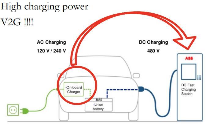
3.4 Electric Vehicle Charging Connectors
There are several charge connectors available on the market with different specifications and capacities. Charge stations can be classified based on power conversion as: (a) Alternating Current (AC) is a class of charge station that makes use of on-board power converter while (b) Direct Current (DC) makes use of off-board power converter without size and weight limitations.
Figure 12: Examples of on-board off-board charger/connectors[8]
The difference between on-board and off-board connector is that on-board makes use of AC source of power supply and every vehicle has its own attached to it which makes it private while off-board makes use of DC source of power supply, and it is universal as it is peculiar to the charge station not to the vehicle which makes it public.
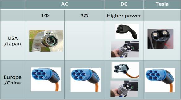
Table 3 shows the DC-AC charging specifications with charging levels, maximum current and voltage each connector dissipates, number of communication pins and maximum power that is expected to deliver when using any of the specified charger with the corresponding rating.
Table 3: AC - DC Charging Specifications AC Charging rating
Plugs Number of pin Communication Charging
Type1 SAE J1772 (US)
Type 2 Mennekes (Europe)
3power pins – L1, N, E 2control pins – CP, PP (PWM over CP)
4power pins – L1, L2, L3, N,E 2control pins – CP, PP (PWM over CP)
Charging level Voltage & current Maximum
Maximum power
AC Level 1 1 Φ 120V, 16A 1.9kW
AC Level 2 1 Φ 240V, 80A 19.2kW
AC Level 1 1 Φ 230V, 32A 7.4kW AC Level 2 3 Φ 400V, 80A 43kW
DC Charging rating
Type 4 SAE J1772 CCS
3power pins –DC+, DC-, E 2control pins – CP, PP (PLC over CP, PE)
Type 4 Chademo 3power – DC+, DC-, E 7 control pins (CAN communication)
Tesla US 3power pins –DC+, DC-, E 3power pins (reused) – L1, N, E 2 control pins –CP, PP
DC level 3 200-1kV DC, 200A 200kW
DC level 3 200-0.5kV, 125A 62.5kW
DC level 3 For model S, 400V,300A
120kW
The charge connectors are designed for purposes either for fast charging or extremely fast charging as shown in table 4. Fast charging increase battery voltage from (350-400) to 800Vandalso charging current pattern for capacitive fade for DC charging only.
TABLE 4: Connectors Specifications and Socket Sets for EV Charging[8]
Val
Review
, Volume 1, Issue 12, pp. 16-23, 2021
These EV connectors and charger are designed with extra capacities and functions. The AC and DC chargers are there for fast and extreme fast charging. Theses sockets helps in fast charging of electric vehicle and reduces power wastage as it takes the exact calculated time to recharge EVs. It also encourages scheduling and priority of EVs as each socket has rated charging time which helps in aligning EVs to a suitable EV station with the specified specification for charging.
IV. CONCLUSION
This comprehensive review showed that EV charging stations were classified into renewable, nonrenewable and hybrid based on its sources of energy generation. From the review it was discovered that there are standards set for EV charging station that were dependent on the charging time and the Efficiency Enhancement (EE)components and connectors. These EE components and connectors enhance and improve power harness from the source to the EV station for fast charging. This review detailed the AC and DC specifications with regards to onboard and off-board connectors and power converters. Finally, this review showed that the best design for EV station is the hybrid of renewable energy sources with a specified EE components and connectors. It was found to be the best because of its numerous advantages as mentioned in the review but above it its entire user friendly and low cost of maintenance. It also took cognizant of Efficient Energy Storage Systems (ESSs) such as Lead or Lithium-ion batteries to serve as backup when the PV is not delivering at its optimum. This review will serve as important guide to EV designers as the merit and demerit of each designed model was elaborated and recommendation given for further research.
REFERENCES
[1] “Medium-Term Renewable Energy Market Report 2015.” http://www.iea.org/topics/renewables/renewablesiea/mtrmr/ (accessed
Oct. 30, 2015).
[2] “first-iea-regional-technology-study-plots-carbon-neutral-nordic-energy @ www.iea.org.” https://www.iea.org/newsroomandevents/news/2013/january/first-iearegional-technology-study-plots-carbon-neutral-nordic-energy.html (accessed Oct. 30, 2015).
[3] C. Youssef and E. Fatima, “A technological review on electric vehicle DC charging stations using photovoltaic sources A technological review on electric vehicle DC charging stations using photovoltaic sources,” in IOP conference series Materials Science and Engineering, 2018, vol. 6, no. 67, pp. 1–10, doi: 10.1088/1757-899X/353/1/012014.
[4] A. L. Bonkaney and S. Madougou, “Impact of Climatic Parameters on the Performance of Solar Photovoltaic ( PV ) Module in Niamey,” mart Grid and Renewable Energy, vol. 8, no. 2, pp. 379–393, 2017, doi: 10.4236/sgre.2017.812025.
[5] S. K. Mahapatro, “Maximum Power Point Tracking (MPPT) Of Solar Cell Using Buck-Boost Converter,” International Journal of Engineering & Technology, vol. 2, no. 5, pp. 1810–1821, 2013.
[6] T. Report, “Feasibility Study of Powering Hazrat Shahjalal International Airport by Solar Power,” 2016.
[7] D. Freeman, “Introduction to Photovoltaic Systems Maximum Power Point Tracking,” no. November, pp. 1–8, 2010, [Online]. Available: www.ti.com.
[8] G. Ram, C. Mouli, P. Venugopal, and P. Bauer, “Future of Electric Vehicle Future of Electric Vehicle Charging Charging ‘ Chicken and egg ’ problem,” 2017.
[9] C. Youssef and E. Fatima, “A technological review on electric vehicle DC charging stations using photovoltaic sources,” in IOP Conf. Series: Materials Science and Engineering, 2018, pp. 1–10, doi: 10.1088/1757899X/353/1/012014.
[10] A. R. Bhatti, Z. Salam, M. Junaidi, B. Abdul, and K. P. Yee, “A critical review of electric vehicle charging using solar photovoltaic,” Internal Journal of Energy Research, vol. 40, no. 9, pp. 439–461, 2016, doi: 10.1002/er.
[11] S. Steinschaden and J. Baptista, “Development of an E ffi cient Tool for Solar Charging,” Journal of energy, vol. 13, no. 29, pp. 1–21, 2020.
[12] A. Al Wahedi and Y. Bicer, “Development of an off-grid electrical vehicle charging station hybridized with renewables including battery cooling system and multiple energy storage units,” Energy Reports, vol. 6, no. 2020, pp. 2006–2021, 2021, doi: 10.1016/j.egyr.2020.07.022.
[13] S. A. Manik, P. J. R. Pavan, and I. Andri, “ScienceDirect ScienceDirect Comparative study on charge controller techniques for solar PV Comparative study on charge controller techniques for solar PV system Assessing the feasibility of Kumar using the heat demand-outdoor temperature function for a Pa,” Energy Procedia, vol. 117, pp. 1070–1077, 2017, doi: 10.1016/j.egypro.2017.05.230.
[14] S. M. Shariff et al., “System Design and Realization of a Solar-Powered Electric Vehicle Charging Station,” IEEE Systems Journal, pp. 1–12, 2019, doi: 10.1109/JSYST.2019.2931880.
[15] J. Caban, “Charging electric cars as a way to increase the use of energy produced from RES,” De Gruuter, vol. 10, no. 98, pp. 98–104, 2020.
[16] M. A. Mohamed and F. A. Mohamed, “Design and Simulate an Off-Grid PV System with a Battery Bank for EV Charging,” Universal Journal of Electrical and Electronic Engineering, vol. 7, no. 5, pp. 1–17, 2020, doi: 10.13189/ujeee.2020.070502.
1, Issue 12, pp. 16-23, 2021