
PORTFOLIO YIFEI KIT TANG
ARCHITECTURE
STATEMENT
Millions of eyes look up at windows, bridges, capers, and they might be scanning a blank page. Many are the cities like Phyllis, which elude the gaze of all, except the man who catches them by surprise...
- Invisible Cities, ITALO CALVINOIdeas are the pursuit among the people and their culture, manifested through the means of materiality into architecture. By inheriting unique constituencies constructs and varying geographical contexts, Architecture expresses the memories of the population through time.
The fabric of cities emerge and diminish as its citizens’ memories - foreign and local - rise and fade. Architectures, in turn, crystallize fragments of moments that tell tales of fossilized memories. Believing that architecture shall be a reflection of people and their cultures, I find myself fascinated by the characters carried through built objects as they express attitudes, agreements and searches - marking the memories of generations, giving forms to the intangibles. Upon such belief, I carefully curate my projects – rendering materiality and memories of places and their citizens
2
1
3 01 00 TARRAGONA SAILING SCHOOL INFORMATION & RESUME P. 05-18 P. 03-04 P. 19-30 P. 31-42 P. 43-44 P. 45-46 P. 47-48 CITY VIEW APARTMENT ADDITION DORCHESTER PUBLIC LIBRARY SPRING GARDEN HOSTEL A BUILDING’S HANDSHAKE ONGOING PROJECTS 02 03 04 05 06 TABLE OF CONTENTS

4 kittang99@gmail.com 5506 Fifth Ave. Pittsburgh www.linkedin.com/in/yifei-tang-74a049192 +1 617-697-8026
ACADEMIC TOOLS
2019 - 2024
Bachelor of Architecture
Carnegie Mellon University
2023
-
AWARDS
2023
International Visiting Semester
Universitat Politècnica de Catalunya
2020 - 2024
EXPERIENCE
2023
2022
Luther S. Lashmit & Louis F. Valentour
Rhinoceros
Grasshopper
2020 - 2024
2020 - 2024
Travel Funding Granted through Open Competition
Deans List Traveling Scholarshps
Granted by the career grades above 3.5 in a 4.0 Scale
Funded Travel & Study in Spain
Researach Assistant
Full time assistant for Research Project carried out by University Professor involving Concrete 3D-Printing and Parametric Design
Monitor for Digital Fabrication Lab
Monitoring the Digital Fabrication Lab in the School of Architecture. Managing machinaries including CNC Router, Laser Cutter, 3D Printer, Robotic Arms, Vacuumn Forming, etc
Teaching Assistant
TA for: Material & Assembly, Digital Media I&II, Drawing I&II, Structural Design I, Materiality & Construction Systems
Photoshop
Illustrator
InDesign
AutoCAD Revit
Vray
Lumion
Drawing
Model Making
Rhino CAM
CURA
Carpentry
Glasswork
Office Suite
MISC
ENGLISH MANDARIN
SPANISH CANTONESE Native Native Proficient - B1 Communicational
5
Summer & Fall September
December Summer

6 TARRAGONA SAILING SCHOOL SITE PLAN

01. TARRAGONA SAILING SCHOOL
2023 FALL INSTRUCTOR: Jordi Adell Roig UPC - ETSAB
Along the endless coast of Tarragona, Spain an array of beaches is scattered. For eons, the tides of the Mediterranean wash the smooth sand as the wind brushes against the rocky cliffs. Nothing has changed much until a sail emerged on the horizon – a ship from a distant empire – announcing the arrival of the Roman settlers. Cities were built and abandoned, civilizations formed and forgotten. Then a thin line of rail prowled across the plain of Catalunya, laying itself along the coast of Tarragona. Hence comes the train, the noise, the visitors, the ancient hospital atop the sandstone cliff and now – riding the same waves that has indifferently embraced the sand and wind -rises a sailing school.
The school situates itself at the junction between a rocky peninsula and a modest beach lined with a lovely boardwalk. The program of the school revolves around a central plazanow acting as the main hangar where sailing boats are docked during off-seasons -- around which all service programs such as changing room, warehouse, repair shop and a small cafeteria are composed around. With higher levels of the building complex made with removable timber, the plaza, changing rooms and cafeteria are constructed with concrete that is cast into the landscape. They will remain long after the school is rendered obsolete -- providing necessary infrastructure for daily uses, or simply mark the remembrance of those who cherished the ancient wind and waves of Tarragona.
7 SITE
AA’ BB’

8 TARRAGONA SAILING SCHOOL A C C’ B’ B

Beach
Staff
9 FLOOR PLAN A’ 01. 02. 03. 04. 05. 06. 07. 08. 09. 10. 11. 12. 13. 14. 15. 16. 17. 18. 19. 20. 21. 22. 23. 24. 25. 26. 27. 28. Beach Access Public Bathroom Kitchen Repair Shop Private Bathroom Storage Reception Hall Entrance System Elevator Bar Reception Outdoor Dining Changing Room Gym Trainer Office Corridor Physical Therapy Athlete Lounge Hangar Main Gate Egress
Walkway
Bathroom
Office
Conference Room
FLOOR PLAN - TARRAGONA SAILING SCHOOL
Atrium Administration
Balcony
Classroom/Assembly

10 TARRAGONA SAILING SCHOOL
ELEVATION
SECTION CC’
SOUTH
9
SECTION AA’

11 SECTION & ELEVATION
10
SECTION BB’

12 TARRAGONA SAILING SCHOOL HANGAR - PLAN & REFLECTED CEILING PLAN 11
PLAZA & CANOPY
The Hangar is the central space around which the sailing school is programmed. A light weight canopy shelters the sailing boats during off-seasons, underneath which the concrete plaza rests in between the stony peninsula and the gentle waves.
THE CANOPY hovers above the expansive hangar space. Its timber skeletal frame dips gently towards the central oculus, where daylight and rain are introduced into the sanctuary. Twenty slender columns span 5.5 Meters on center to support the massive canopy. They are covered with reflective stainless steel and gradually taper down as they touch the ground. In between them drape mesh curtains, which are operable through a series of pulley system, allowing optimal control over the interior climate.
THE PLAZA -- now serving as the dry dock of the sailing boats -- is cast permanently into the coast of Tarragona. Along with the modest, single story structures that surround it, the plaza will remain as a necessary infrastructure that oversees the coastline long after the obsolescence of the sailing school. The floor of the Plaza is lined with concrete tiles, among which three water canals converge at the center. Water collected from the drainage system in the surrounding structures are channeled through the canals into the central pool -- underneath a frame of clear sky freed by the oculus above.


13 MAIN HANGAR CONSTRUCTION SECTION - HANGAR HANGAR - PLAZA
DETAILING

THE HANGAR is conceived to be a semi-outdoor space with minimum enclosure. Twenty columns, which carry the timber frame canopy, are wrapped in polished metal sheathing. Dematerialized under the sun, they frame the view towards the ocean.
THE CURTAINS are situated in between the columns. They are anchored against the pedestals and the heavy timber beams of the canopy. A series of cable mechanisms are applied to raise and lower the curtain based on weather condition. The metal mesh screen appear translucent from afar while bearing the capability to protect the sailing boats from heavy rains and wind.
The CEILING of the canopy is lined with the same material of the curtain. They provide a sense of ambiguity that stands contrast against the Oculus in the center. Together, they gently frame the gateway towards the ocean, capturing a piece of serenity between the wave and the wind.

14 TARRAGONA SAILING SCHOOL
HANGAR LOOKING TOWARDS OCEAN
AXONOMETRIC - CURTAIN SCREEN ASSEMBLY

15 MAIN HANGAR
AXONOMETRIC - DRAINAGE
DRAINAGE & PLAZA STAIRS
PERSPECTIVE - PLAZA STAIRS

CONSTRUCTION
16 TARRAGONA SAILING SCHOOL
SECTION - WAREHOUSE
STORAGE WAREHOUSE

THE WAREHOUSE is situated on the Northern end of the hangar. This elongated space is supported by a modest timber frame, which houses a series of windows and skylights to ensure sufficient natural light intake.
THE FACADE is lined with Polycarbonate Louvers, which brings in diffused daylight while allowing for natural ventilation across the storage space. The facade that faces the street is to have an array of view ports, which is operable based on the weather condition while affording the passerby a peak into the sailing school. The Southern Facade, however, is punctured with large openings -both enclosed and fully open -- that bring the ocean view into the warehouse.

17 STORAGE WAREHOUSE
INTERIOR - WAREHOUSE
DETAILED PLAN - WAREHOUSE
 INTERIOR ELEVATION
TARRAGONA SAILING SCHOOL 17
INTERIOR - CORRIDOR
 INTERIOR
- OFFICE AXONOMETRIC - MAIN STAIR
STAIR LANDING LOOKING TOWARDS WEST INTERIOR 18
INTERIOR
ELEVATION - OFFICE
CITY VIEW APARTMENT ADDITION
With BRIAN HARTMAN & COLIN WALTERSCoordinated by GERARD DAMIANI
SoA | Carnegie Mellon University | 2022
Designed and constructed in the 1960s by I.M. Pei, the City View Apartments is part of an urban planning project in Pittsburgh, Pennsylvania that was never completed. Our comprehensive studio reimagines this residential project brought to fruition.
By applying a sectional strategy of an iconic precedent, the massing and planning stages of the design is drastically accelerated, leading to the focus on resolving structure, systems and enclosure. Through analyzing and documenting the existing structure and participating in various meetings with professional consultants, our group developed comprehensive designs that aim to create elevated living experiences while accommodating the residents of the existing tower.
The proposed concrete frame houses various apartment unit types while maintaining the original structural language. Perforated aluminum and bronze panels clad the southern facade, delivering a monolithic elevation that shifts its transparency across the skyline. A moment frame foundation flows along the undulating topography, giving the public space back to the community. The exterior envelope for the Northern facade is glazed through various transparencies, providing residents with living areas bathed in diffused light and single loaded corridors become “streets in the sky” , elevating the living above the roaring streets of the Steel City.

20 CITY VIEW APARTMENT
19

21 OVERVIEW 20

UNITS & TETRIS
The floor plan and units layout are generated from studying Robinhood Garden, carrying down its unique Tetris-like unit integration. The new City View tower consists 8 threestory zones each containing 13 residential units that are served by one enclosed corridor on the middle level. Each zone contains 1-bed, 2-bed, 3-bed and accessible studio unit types, covering wide range of demands. The addition of accessible units generates a different interlocking layout from the Robinhood Garden design. The accessible units are directly accessed by the middle level and are equipped with ADA interior programs to ensure accessibility.


CITY VIEW APARTMENT
21


STRUCTURE
The new addition of the building has a cast in place concrete moment frame base. Concrete columns spanning 52’ O.C. flow along the topography, generating a large open space for the public program. Joints and certain portion of the plenum are thickened to accommodate additional load from the structures above.
The main section of the building is supported by shear walls spacing 26’ O.C. With additional lateral supporting wings and 6” concrete floor plates spanning every 9’, they form a rigid frame system that houses the residential units. Interior and non-load bearing walls are pre-made off site with cold rolled steel frame finished with dry wall or wood boards.

23 STRUCTURE & PARTI
INTERIOR PLANNING
All units are accessed through the middle level within the threestory chunk. The entrance level consists kitchen, dining space and a half bath -- although some unit types have additional living space planned into the corridor level. Interior stairs lead to private sections of the program, including master bedroom, living room and guest rooms. Each bedroom is equipped with a full bathroom while some master bedroom enjoy features such as walk-in closets. Due to the shear wall rigid frame structural system, interior walls are minimized. Service areas such as bathrooms, closets and laundry rooms are utilized as dividers of the spatial programs, generating large, open living spaces.


24 CITY VIEW APARTMENT
FLOOR PLAN APARTMENT UNIT MODEL


25 UNITS
FLOOR PLAN with ORIGINAL STRUCTURE
INTERIOR RENDER - KITCHEN
INTERIOR RENDER - BEDROOM
INTERIOR RENDER - LIVING ROOM
INTERIOR RENDER - BALCONY


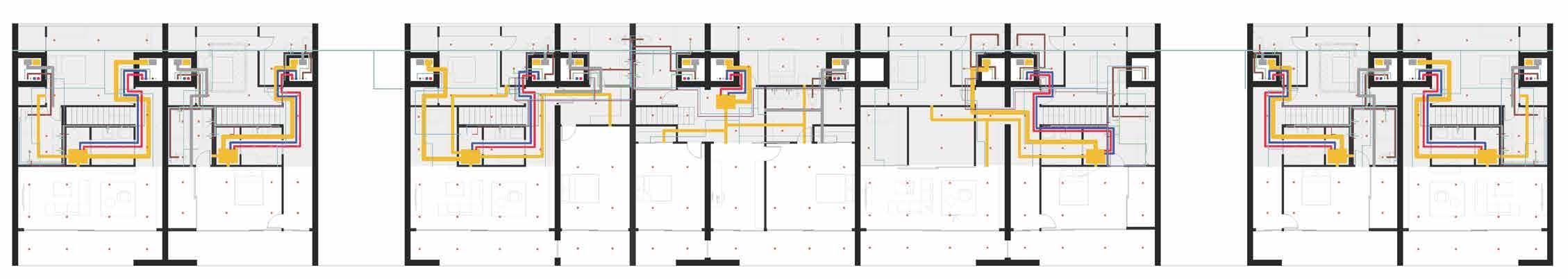

SYSTEMS
Each unit is served with an individual heat pump system. Two air handling units -- one for each floor -- draw and dispose heat from two water loops that run through the building at a relatively constant temperature between 55 to 85 degrees Fahrenheit. All the pipes (Air Intake, Exhaust, Water Supply, Black & Gray Water Plumbing, etc) run vertically through the building through the system shafts that flank the shear walls.
Drop Ceilings house pipes that travel horizontally within the apartment units. They are condensed within the North and central part of the interior space, leaving the Southern side largely open for daylight and view access. Sprinklers travel through egress cores and travel horizontally into the units.
26 CITY VIEW APARTMENT
SYSTEM CEILING PLAN SYSTEM MODEL


27 SYSTEMS OVERVIEW CONSUMABLE WATER F1 PLAN F1 PLAN F1 PLAN F1 PLAN F1 PLAN F1 PLAN F2 PLAN F2 PLAN F2 PLAN F2 PLAN F2 PLAN F2 PLAN PLUMBING CEILING COMPOSITION DUCT - INTERIOR DUCT - CORRIDOR


EGRESS
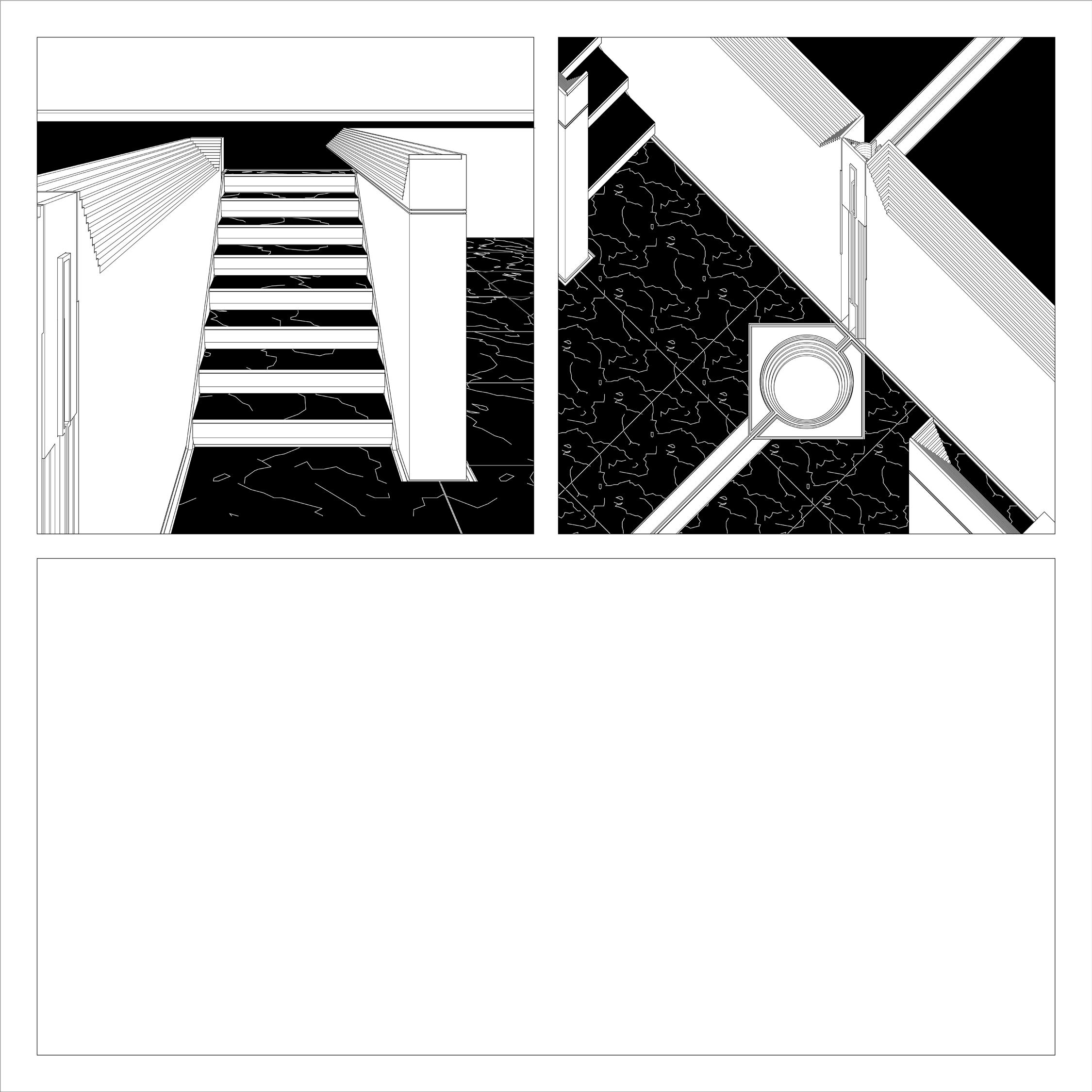
The egress core on the West end of the new tower is expressed as an open, sculptural space. Each multi-story cavity contains a series of public rooms and three sets of stairs that are lined with translucent panels as railing. As sun light enters the egress core through the southern panel glazing, it fills the vertical space with various shades of brightness, complementing the sculptural aggregation while encouraging communal interactions.

28 CITY VIEW APARTMENT
LEFT TOP:
LEFT BOTTOM:
MIDDLE:
RIGHT TOP:
RIGHT BOTTOM:
EGRESS MODEL
CROSS SECTION 1
LONG SECTION
STRUCTURAL MODEL
CROSS SECTION 2


29 SECTION & EGRESS

Hypothesis:
Hypothesis:
Hypothesis:

sDA: 86.4%
sDA: 86.4%
ENCLOSURE
The southern facade is clad with perforated metal panels to ensure privacy and strategic shading. The panels -- two shades of silver and two bronze -showcase the Tetris-Locking parti of the units. All panels are perforated by the programming behind the enclosure: the diameter of the foramina range from 6-1/2” (in front of glazings) to 2-1/2” (in front of solid walls), generating various levels of transparency across the facade.
Facade panels are attached to the concrete frame through a series of aluminum scaffolding and bracings that bear both vertical and lateral loads. These modularized panels can be operated freely, offering full control of interior shading based on preference while generating unplanned facade patterns.
The north facade is entirely glazed. Different levels of privacy of the interior programming is expressed through the variation of transparency of the glazing. Bedrooms and corridors would have windows enclosed with clear glass, whereas more private space like bathrooms would be glazed with frosted glass, which provides both natural light and privacy. East and West facade is left unglazed to showcase the structural logic. Multi-story window slots scatter across the facade, providing view access for the end units.
Adjusting the input imagery will be necessary to address annual sunlight exposure values. By reintroducing more intermediate values within the input, more smaller holes will be added with the goal of reducing a small but meaningful amount of ASE.
Adjusting the input imagery will be necessary to address annual sunlight exposure values. By reintroducing more intermediate values within the input, more smaller holes will be added with the goal of reducing a small but meaningful amount of ASE.
Materials:
Materials:
Materials:

ASE: 10.2%
ASE: 10.2%
ASE: 10.2%

UDI: 65.8%
UDI: 65.8%
UDI: 65.8%
Adjusting the input imagery will be necessary to address annual sunlight exposure values. By reintroducing more intermediate values within the input, more smaller holes will be added with the goal of reducing a small but meaningful amount of ASE.
-Structural Wall: Finished with Gympsum, Painted White
-Interior Partition: White Painted Walls
-Structural Wall: Finished with Gympsum, Painted White
-Structural Wall: Finished with Gympsum, Painted White
-Floor: Hardwood Floor
-Interior Partition: White Painted Walls
-Interior Partition: White Painted Walls
-Floor: Hardwood Floor
-Ceiling: Panelized Wood Finish
-Floor: Hardwood Floor
-Facade: Bronze or Stainless Steel (depending on unit)
-Ceiling: Panelized Wood Finish
-Ceiling: Panelized Wood Finish
-Facade: Bronze or Stainless Steel (depending on unit)
-Facade: Bronze or Stainless Steel (depending on unit)
Conclusions:
Conclusions:
Conclusions:
ASE is reduced by about 2%. While not a huge amount, the space will be more comfortable for occupants without sacrificing daylight availability.
ASE is reduced by about 2%. While not a huge amount, the space will be more comfortable for occupants without sacrificing daylight availability. amounts
ASE is reduced by about 2%. While not a huge amount, the space will be more comfortable for occupants without sacrificing daylight availability.

30 CITY VIEW APARTMENT amounts of glare will White unit) only the ample increasing future
of glare will White unit) only the ample increasing future
amounts
of glare will White unit) only the ample increasing future
UDI
SOUTH FACADE RENDERING
1 TO 1 SCALE MOCK-UP 1
1 TO 1 SCALE MOCK-UP 2
SOUTH ELEVATION


ENCLOSURE 1. 2. 3. 4. 5. 6. 7. 8. 9. 10.
UNIT
FACADE TRANSPARENCY PERFORATION PATTERN CLADDING FOR
sDA ASE
30


DORCHESTER PUBLIC LIBRARY
2022 SPRING - Carnegie Mellon University - School of Architecture Coordinator - JEREMY FICCA Instructors - GERARD DAMIANI & ERICA COCHRAN HAMEEN

32 DORCHESTER PUBLIC LIBRARY
31

Among the humble red bricks of Dorchester, Massachusetts lies a library that acts as a sanctuary. Dorchester has remained there – a witness to the rapid expansion of the nation. Facing Columbia Road and backing a historical cemetery, the library’s site is, and has always been, a junction between roaring currents of the purposeful and the quiet retreat of the wanderers.
Ever since its establishment in the early 1800s, Columbia Road has been a major artery that channels cars and pedestrians through Dorchester and Boston. Visual connections from the interior of the library relate to the directional movement of the road and sidewalk. On the other side, the cemetery sits quietly through centuries of oceanic wind. Careless squirrels twirl through the shadow of the ancient trees as aimless wanderers stumble across the moss of nameless stones – every movement is freed from the linear efficiency of urban life.
Bridging the phantom of tail lights flashing by and the empty tequila bottles left behind, a library stands as a terminal that facilitates two systems of movements – bringing visitors from two worlds that hardly meet while sanctuarizing the moments of encounter among this post-pandemic society.


33 OVERVIEW


TERMINAL OF MOVEMENTS
The lower floor is designed for transparency. The majority of the room is enclosed with glass panels except for the private areas such as bathrooms and utility chamber. The entrances of the building are set to the back side of the parcel, working alongside with the glass façade, the vista of the cemetery is largely celebrated.

PURPOSEFUL CONFLUENCE WANDERER
Whether being a commercial street that hosts various shops or a widened highway where viechles canal, the west side of the parcel is marked with rushing purposes.
Bridging the phantom of the tail light flashing by and the empty Tequila bottles left behind, the library shall be a terminal that facilitates two systems of movements.
Trees and headstones become gravitational points around which the movements of the people revolve, giving the seemingly random motions a hidden pattern.
34 DORCHESTER PUBLIC LIBRARY
CONCEPT MODEL

The utility spaces, such as meeting rooms, bathrooms and system rooms are pavilionized as objects. They are the destinations where movements revolve around. The negative spaces generated by those objects become hot zones where the flow of motion densifies -- transforming them into pockets of surprises.
The meeting room and maker spaces are enclosed as bubbles within opening. Application of curtains ensures controllable privacy.
The central area is left unprogrammed for the gathering of people. In time needed, the library is equipped with the room and means to be converted for various purposes, such as hosting vaccination centers, small fairs, and temporary sanctuaries.
It is within those moments of encounters that the community lives.
35 PLAN AS TERMINAL
FIRST FLOOR PLAN
CONVERSION - GALLERY
CONVERSION - VACCINATION CENTER
CONVERSION - FAIR


STACKS
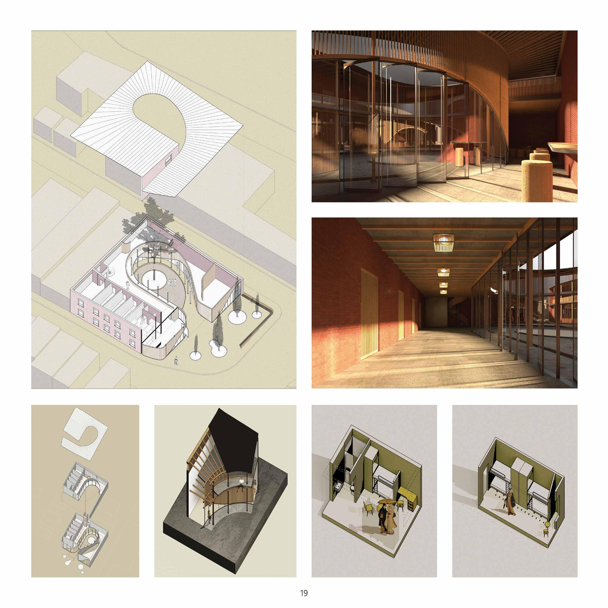
The upper floor is entirely dedicated to the books. Customized shelves vary in height and forms, but never exceeds eye level. Their arrangements are carefully composed to facilitate the movements of the visitors but leave the space visibly open. Gradient density louvers span across the east and west façade according to the program. Those in front of the bathroom and computer booths are designed to be denser to ensure privacy and avoiding glares on the screens. The rest of the façade areas are cladded with relatively larger spans, providing sufficient daylight intake and view accessibility. The roof flows along the profile of the canopy, crowning the reading area with pleasant elegance. Three oculi are generated by the flow of the roof curvatures, through which direct daylight is brought down to the visitors -- setting free the mind of the readers, beyond the flow of the canopy.
36 DORCHESTER PUBLIC LIBRARY
STRUCTURAL FRAME
SECOND FLOOR PLAN
ROOF & OCULI


READING AREA


37 PLAN AS SANCTUARY
SUMMER DAYLIGHTING CHILDREN AREA
WINTER DAYLIGHTING
STRUCTURE
The library sits on a column grid that span 20 feet apart, creating a large open area that allows the composition of utility pavilions and flexible arrangement of the furnitures. Glue laminated timber columns with 8” by 8” cross section taper in towards the bottom, hovering 1/2” above the ground over stainless steel footings. 1 foot deep glue laminated beams are braced onto the columns through a series of customized steel joints, holding up the cast in concrete floor plates on top. An additional layer of 4” thick timber sheet is applied over the exposed part of the steel joints, protecting the metal from potential fire and heat. The beams on the second floor curve along the flow of the roof, holding the canopy while housing system pipes within the grid cavities. A matrix of light weight plywood louvers made through CNC processes are hung over the roof beams, shielding the systems while emphasizing the flow of the roof.

38 DORCHESTER PUBLIC LIBRARY GLASS DOUBLE BRONZE GLASS DOUBLE GLASS 5’0” 19’0” 35’6” 45’0” ROOF DRAIN GLASS PANEL PIVOT SHAFT BRONZE PANEL DOUBLE INSULATED GLASS BRONZE ENCASED LOUVER 6” RIGID INSULATION BRONZE END SHEATHING BRONZE END SHEATHING GLASS PANEL PIVOT SHAFT DRAINAGE CHAIN DOUBLE INSULATED GLASS GLASS PANEL PIVOT SHAFT DRAWINAGE & POOL 5’0” WATER STOP 18*18 CONCRETE PIER 1’ DAMP WALL 19’0” 35’6” 45’0” ROOF CLADDING 8” INSULATION WATER PROOF AIR GAP CEILING CLADDING 24*6 GLUE LAMINATED BEAM CEILING CLADDING PLYWOOD LOUVERS LIGHTING 30*12 GLUE LAMINATED BEAM BEAM-COLUMN JOINT SPRINKLER 18*18 GLUE LAMINATED COLUMN AC AIR INTAKE AC AIR OUTPUT RAILING-PIPE THROUGH-FLOOR JOINT POLISHED CONCRETE FLOOR FINISHING 6.5” CLT AIR SPACE & SYSTEM CEILING CLADDING 24*6 GLUE LAMINATED BEAM CHROME REFLECTION VAULT WATER PIPE POURED CONCRETE FLOOR FINISHING 6” CONCRETE ROUGH BOARD RIGID INSULATION AC AIR OUTPUT CHANNEL AC AIR INTAKE CHANNEL CONCRETE RAFT FOOTING UNDISTURBED SOIL 18*18 CONCRETE PIER 0’0” 1’0” 2’0” 4’0” 8’0” 16’0” 0” 6” 12” 24” 48” 1’0” = 6” 96”
TIMBER JOINT DETAIL SECTION & DETAIL
39 STRUCTURE ROOF CLADDING ROOF DRAIN GLASS PANEL PIVOT SHAFT BRONZE PANEL DOUBLE INSULATED GLASS BRONZE ENCASED LOUVER 6” RIGID INSULATION BRONZE END SHEATHING BRONZE END SHEATHING GLASS PANEL PIVOT SHAFT DRAINAGE CHAIN DOUBLE INSULATED GLASS GLASS PANEL PIVOT SHAFT DRAWINAGE & POOL 5’0” WATER STOP 18*18 CONCRETE PIER 1’ DAMP WALL 8” INSULATION WATER PROOF AIR GAP CEILING CLADDING 24*6 GLUE LAMINATED BEAM CEILING CLADDING PLYWOOD LOUVERS 30*12 GLUE LAMINATED BEAM BEAM-COLUMN JOINT SPRINKLER 18*18 GLUE LAMINATED COLUMN AC AIR INTAKE AC AIR OUTPUT GLASS RAILING THROUGH-FLOOR JOINT POLISHED CONCRETE FLOOR FINISHING 6.5” CLT AIR SPACE & SYSTEM CEILING CLADDING 24*6 GLUE LAMINATED BEAM CHROME REFLECTION VAULT WATER PIPE POURED CONCRETE FLOOR FINISHING 6” CONCRETE ROUGH BOARD RIGID INSULATION AC AIR OUTPUT CHANNEL AC AIR INTAKE CHANNEL CONCRETE RAFT FOOTING UNDISTURBED SOIL 18*18 CONCRETE PIER 19’0” 35’6” 45’0” ROOF CLADDING 8” INSULATION WATER PROOF AIR GAP CEILING CLADDING 24*6 GLUE LAMINATED BEAM CEILING CLADDING PLYWOOD LOUVERS LIGHTING 30*12 GLUE LAMINATED BEAM BEAM-COLUMN JOINT SPRINKLER 18*18 GLUE LAMINATED COLUMN AC AIR INTAKE AC AIR OUTPUT RAILING-PIPE THROUGH-FLOOR JOINT POLISHED CONCRETE FLOOR FINISHING 6.5” CLT AIR SPACE & SYSTEM CEILING CLADDING 24*6 GLUE LAMINATED BEAM CHROME REFLECTION VAULT WATER PIPE POURED CONCRETE FLOOR FINISHING 6” CONCRETE ROUGH BOARD RIGID INSULATION AC AIR OUTPUT CHANNEL AC AIR INTAKE CHANNEL CONCRETE RAFT FOOTING UNDISTURBED SOIL 18*18 CONCRETE PIER 0’0” 1’0” 2’0” 4’0” 8’0” 1’0” = 1/2” 16’0” 16’0” ROOF CLADDING ROOF DRAIN GLASS PANEL PIVOT SHAFT BRONZE PANEL DOUBLE INSULATED GLASS BRONZE ENCASED LOUVER 6” RIGID INSULATION BRONZE END SHEATHING BRONZE END SHEATHING GLASS PANEL PIVOT SHAFT DRAINAGE CHAIN DOUBLE INSULATED GLASS GLASS PANEL PIVOT SHAFT DRAWINAGE & POOL 5’0” WATER STOP 18*18 CONCRETE PIER 1’ DAMP WALL 8” INSULATION WATER PROOF AIR GAP CEILING CLADDING 24*6 GLUE LAMINATED BEAM CEILING CLADDING PLYWOOD LOUVERS 30*12 GLUE LAMINATED BEAM BEAM-COLUMN JOINT SPRINKLER 18*18 GLUE LAMINATED COLUMN AC AIR INTAKE AC AIR OUTPUT GLASS RAILING THROUGH-FLOOR JOINT POLISHED CONCRETE FLOOR FINISHING 6.5” CLT AIR SPACE & SYSTEM CEILING CLADDING 24*6 GLUE LAMINATED BEAM CHROME REFLECTION VAULT WATER PIPE POURED CONCRETE FLOOR FINISHING 6” CONCRETE ROUGH BOARD RIGID INSULATION AC AIR OUTPUT CHANNEL AC AIR INTAKE CHANNEL CONCRETE RAFT FOOTING UNDISTURBED SOIL 18*18 CONCRETE PIER 19’0” 35’6” 45’0” ROOF CLADDING 8” INSULATION WATER PROOF AIR GAP CEILING CLADDING 24*6 GLUE LAMINATED BEAM CEILING CLADDING PLYWOOD LOUVERS LIGHTING 30*12 GLUE LAMINATED BEAM BEAM-COLUMN JOINT SPRINKLER 18*18 GLUE LAMINATED COLUMN AC AIR INTAKE AC AIR OUTPUT RAILING-PIPE THROUGH-FLOOR JOINT POLISHED CONCRETE FLOOR FINISHING 6.5” CLT AIR SPACE & SYSTEM CEILING CLADDING 24*6 GLUE LAMINATED BEAM CHROME REFLECTION VAULT WATER PIPE POURED CONCRETE FLOOR FINISHING 6” CONCRETE ROUGH BOARD RIGID INSULATION AC AIR OUTPUT CHANNEL AC AIR INTAKE CHANNEL CONCRETE RAFT FOOTING UNDISTURBED SOIL 18*18 CONCRETE PIER 0’0” 1’0” 2’0” 4’0” 8’0” 1’0” = 1/2” 16’0” 1’0” = 1/2” 16’0”

40 DORCHESTER PUBLIC LIBRARY SECTION


SYSTEMS
Systems are designed to be the vessel of the building. 4 Large air conditioning towers pierce through the floor – their presence becomes object themselves. The glass panels that clad the façade of the lower floor remain closed during the cold winter of Massachusetts and can be pivoted open during the warmer time of the year. Cooler air above the reflecting pool gets sucked into the building, it travels along the AC shafts through the floor openings and leave the building via the ventilation windows around the oculus on the roof. Fire sprinkler pipes are celebrated as indicators of pathways. With lighting fixtures and reflection louvers installed on top of the brass tubes, they shower the library floor with diffused light, guiding visitors through the field populated with pavilions.
41 SYSTEMS
40


42 DORCHESTER PUBLIC LIBRARY BATHROOMS MAKER SPACE RESIDENCE FIRE STATION ROOF TOP ROOF BOTTOM F2 19’ 36’ 45’ 5’ F1 CONFERENCE ROOM
STREET VIEW
41
STREET ELEVATION

COMMUNITY
As the spring breeze whistling across the hanging eaves of the library, the city gently awakes from the shrouds of the pandemic. Roaring vehicles start to fly by the quiet neighborhood, gradually populating the old streets of Dorchester. Unbothered wanderers float underneath the sprouts among the ancient trees, wondering about what surprises await them ahead of the morning sun. They proceed, turn, run into each other at the junction of pavilions. They nod, smile, reach out to pick up the same book. It feels just like the old days, where the wind carries the unrecognizable chattering across racks of books, the community revives among the encountering of its citizens.
43 DETAILING & ENCLOSURE COMPUTERS CHILDREN ZONE & COMMUNITY CENTER COMFORT KITCHEN CEMETERY
VAULT LIGHTING
LIGHTING DETAIL & FIRST FLOOR
REFLECTION
MOUNT SPRINKLER PIPE

SPRING GARDEN HOSTEL
Sitting at a crossroad in the small neighborhood of Spring Garden, the hostel aims to provide a private and comfortable retreat for both locals and visitors to gather and enjoy community activities.
The main entrance faces the busy crossroad and shelters the public program, which is arranged along a linear circulation that revolves around a central garden. The sleeping quarters are nestled inside an existing brick wall that used to house a local factory, providing privacy while ensuring sufficient natural lighting. Facade composed with glass mullions and wooden louvers direct views towards the inner garden, with varying transparency adequate to the accordance spatial programs, they guide visitors along a sequence of delicate spaces, funneling the focus and activities towards the center.
2021 SPRING Coordination Instructor - - JEREMY FICCA KYRIAKI GOTI ROOF PLANPLAN
AA’ SOUTH-WEST ELEVATION FIRST FLOOR PLAN 43 SPRING GARDEN HOSTEL
SECOND FLOOR
SECTION
CIRCULATION PROGRAM STRUCTURE MAIN CIRCULATION - ATRIUM MAIN CIRCULATION - CAFE DORM ROOM 44 PROJECT SUMMARY FAMILY SUITE


A BUILDING’S HANDSHAKE
A door handle is the first greeting from a building - a proper gesture that introduces the architecture.
This project explores - in two stages - the progress of designing, prototyping, and manufacturing in the materialization of building details.
The first door handle is conceived under a subtractive process through 4-Axial CNC router, while the second one is to be understood as a casted volume. From their different manufacturing logics, corresponding materials, forms and scales generated themselves naturally, showcasing unique attitudes and personalities.

46
DESIGN CONCEPT FABRICATION
PROTOTYPE 1
A BUILDING’S HANDSHAKE
PROTOTYPE 2

PROTOTYPE 1
CASTING TRIAL 1
MOLDING COLLECTION
DESIGN CONCEPT
MOLD DESIGN
ASSEMBLY PROTOTYPE 2 46 PROJECT SUMMARY
MOLD


ONGOING PROJECTS
Left : A series of objects made through mixed fabrication medium to explore the boundary between drawing and modeling. Through case studies and project designing, the connotation of architectural representation is reimagined.
Right : Selected work from project concept sketches in searching for form & presence. Charcoal & Pastel on newsprint.


48
ONGOING PROJECTS


49 DRAWING & MODELING

2 2 0 4