An architect plays a much larger role within society compared to what the average person realizes. From my primary and secondary research on the topic of the role of an architect, the basic level that most people think of is someone with the skills and ability to design constructible buildings that allow for the creation of inhabitable space. While it’s clear this is an essential facet of what makes an architect, especially within the civil realm, an architect’s role greatly supersedes what is stated above. An architect is further given the essential challenge of serving not only as a bridge between every profession in the world, but also as a bridge between the professional world and communities all over the world that are often left out of mind, and certainly not often considered as ideal clientele for the typical architect. It wasn’t until architects such as Shigeru Ban from Japan, and Sambo Mockbee, the founder of Rural Studio that dramatic shifts were made in the mindset of architects towards serving all communities, not just those that will make them the most money and yield the best portfolio pages.
When considering the architect’s role in the civil realm, an underlying building block that must be regarded is the ethical standards that architects work under. These standards, in the United States at least, are layed out by the AIA Code of Ethics and the NCARB Model Rules of Conduct. Both documents, in a broad but crucial sense, compel architects to “protect public health, safety, and welfare.” This statement immediately takes architects out of the bubble of individual projects and moves the scope into the public as a whole,
which creates a whole lot of more responsibility than an architect who is only thinking about if they can design a building that is inhabitable for their clients. This responsibility, however, is what architects must build on and use to create designs that serve the community and protect them in as many ways as possible. In the AIA code of ethics, besides upholding the law, which is heavily mentioned by NCARB and the AIA, architects have an ethical obligation to “uphold human rights in all their professional endeavors.” This is clarified to pertain to any harassment or discrimination on the “basis of race, religion, national origin, age, disability, caregiver status, gender, gender identity, or sexual orientation.” I think this is one of the most important rules in the Code of Ethics for architects to actively consider, because this is something that can easily slip the mind when trying to create some fantastical design for a wealthy client. As stated earlier, architects serve as the bridge between communities, and in order to cultivate the creation of positive human experiences, every aspect of the people that make up these communities must not only be considered but respected and taken to heart so as not to even unintentionally leave a group of people out of the vision. With this idea of considering all groups of people, as a general obligation in the AIA code of ethics, it’s stated that architects should “design for human dignity” … “Members shall not knowingly design spaces intended for torture, including indefinite or prolonged solitary confinement.” This relates to the argument by Bryan Stevenson in the New York Times article, “Slavery gave America a fear of black
people and a taste for violent punishment. Both still define our criminal-justice system.” The title alone gives a good representation of this connection because our prisons, holding several million people and a vastly disproportionate share of the world’s imprisoned people, have largely targeted black people and other minorities. This creates a power differential that allows for free labor and mass control by the majority that has always held power in this country. Therefore it goes against so many ethical obligations as architects to design spaces in the willing and knowing aid to the continuation of this system. Lastly from the AIA Code of Ethics, I appreciate the section that discusses the obligation to the environment since architecture and the built environment play such a huge role in impacting the earth and its limited natural resources. It is therefore essential that architects keep the environment and climate change at the forefront of our minds while designing buildings because it will protect the long-term health, safety, and welfare of the public by fewer people being forced out of their homes from extreme heat and rising seas.
Architecture from a humanitarian standpoint is a topic that has not always existed, and as stated earlier, the architects Shigeru Ban and Samuel “Sambo” Mockbee, while from different parts of the world, are essential human case studies on understanding what it means to go above and beyond in taking action on architectural ethics. Shigeru Ban is a Japanese Architect and Pritzker Prize winner and is one of the first notable architects to take projects that focused on efforts to create affordable,
temporary architecture as humanitarian relief for natural disasters. He has been very innovative in his materiality exploration in using paper as structure, and other recycled items like old barrels and tires. Sambo Mockbee was an American Architect who started Rural Studio in rural Alabama, which, as seen in the documentary, “Citizen Architect Love Stories,” provided a unique opportunity for architecture students at Auburn University to go into an underserved community in order to affordably design and build a house or other communityfocused building however they see fit. Creating meaningful architecture for those who wouldn’t typically have the means to afford to hire or even find an architect is of growing importance in our field. Designing and constructing an equitable built environment for all to experience and cultivate spaces that allow for everyone to live their best lives is a seemingly impossible goal, but one that should be strived for by architects all over the world.
Six weeks have passed since my previous thoughts which expressed what I believed to be the role of architects, especially from a civic and humanitarian perspective. I never doubted the crucial and potentially powerful role architects play in shaping communities, but I’ve come to question how often, and whether or not this power is always wielded in the most positive and productive ways. It might be strange to describe the role of an architect as “potentially powerful,” but I’ve come to learn especially recently that it takes a lot more than an architect to create architecture. The determining factor on if an
PAGE 82 PAGE 83
MANIFESTO
MANIFESTO
MANIFESTO LAB 01
ARCHITECTURAL SYSTEMS INTEGRATION 3.2


architect conceives powerful architecture that initiates positive ripples throughout communities is if the architect isn’t the sole mind behind the project. Rather, an analogy I might use is the architect as a composer. As a composer is inspired and influenced by the world around them to write music and organize a band full of instruments of different pitches, uses, timing, and more, an architect does the equivalent with buildings and spaces. As a master compiler of as many influences ranging from society, structure, material, ethics, and much more, both find purpose in meaningful production from these influences. The architect produces purpose by predicating positive power by serving the influences that surround them, not by serving themselves and imposing their vision on the world. While six weeks ago was not long ago relatively speaking, my attitude has shifted from what I believed an architect to be and should be. I think it is time I begin to let down the architect from their “high horse” and put the person before the product. Let the architect be the occupant before the designer, as that will only make the design more appreciated and cherished by the people as a whole.
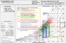
LAB 01: SITE ANALYSIS - NATURAL SYSTEMS
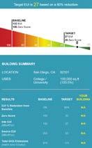
Project Location: San Diego, California Project Size: 60,000 SF College/University, 30,000 SF Multifamily Housing, 10,000 SF Restaurant

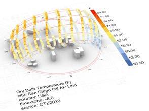
Climatic Conditions:
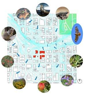
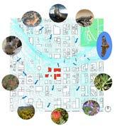
Ecosystems: Encircling the map above is a variety of native plant and animal species to San Diego. The increase in urbanization is detrimental to all native species, and because of the interconnected nature of native plants and animals in providing habitats, food, clean air, and more, it is essential to have open natural spaces such as Balboa Park featured in the uppr right of the map that creates a safe spce for these plants and animlas to thrive.
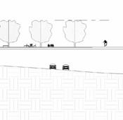
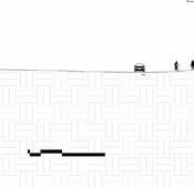
lies on the top of a hill, at approximately 114 feet above sea level. The site is directly adjacent to a sunken freeway which is followed by a sharp increase in slope on the other side. Nevertheless, the areas right around the project location are very walkable due to a relatively small slope.
Hydrology: As indicated in the upper map and the one to the left, water flow to the San Diego Bay combined with the effects of global warming will cause an increase in sea level. In a 2022 report from the National Oceanic and Atmosphereic Administration states that the ocean levels will rise by inches by 2050, which have large effect in an area like San Diego built so close to the ocean. The overall watershed that encompasses our site and most of the downtown San Diego is the Pueblo Watershed.
Air Quality: The Air Quality, according to the Air Quality Index (AQI) is generally considered “good” at an average of 39. According to IQ Air, since 2018, the primary pollutant of PM2.5 in the area has improved by 32% which shows lots of positive progress. However, San Diego still is one of the worst cities in the US when it comes to smog, which indicates high levels of visible air pollution.
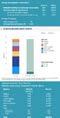
Goal Setting (Energy):
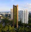
EDEN Singapore Apartments Heatherwick Studio Ellis Residence Coates Design Architects

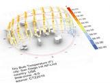
SUN PATH DIAGRAM (Historic Data)
Internal Heat Gain: Through the use of material and wall assemblies with higher U-values, reducing the WWR to feature less glazing, better insulation with higher R-values, thicker walls in general, and more are various ways of reducing the internal heat gain found in buildings. Furthermore, such as in the example to the left, improved material assemblies, more efficient lighting, and less required electricity use in general also aids in reducing internal heat gains. Shanghai In-Bund Office Building HPP Architects
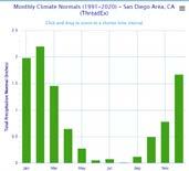
MONTHLY PRECIPITATION CHART (Historic Data)
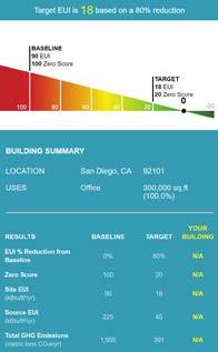
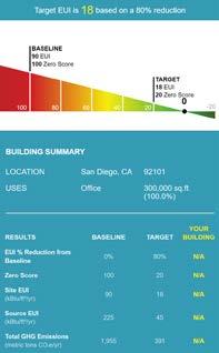
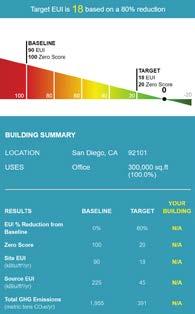
Based on the Target EUI found from Zero Tool, and exmaining the load profile given by Zero Code, there are tasks that can be done to reach the Target. There is almost no difference in the EUI in kBtu/SF/yr, and the largest energy use for the project expected to come from plug loads, followed by hot water, fans, and interior lighting. This presents a solvable challenge of decreasing energy usage by optimizing applicance usage, types of lighting, cooling strategies, and more. Because the estimated Site EUI already lower than the target, only small adjustments should be made, but larger ones can still be made to make the energy Net Positive and further reduce energy usage from the baseline.

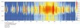
HOURLY TEMPERATURE CHART (Historic Data)
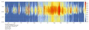
Produced by Weather.gov
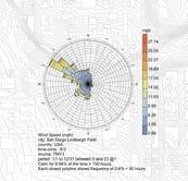
WIND ROSE (Historic Data)
PAGE 84 PAGE 85
Topography: As featured in the map above, there are a variety of topographical changes around our project location. Despite being close to the ocean, our site
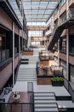
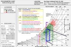
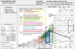
Top 5 Passive Design Strategies (Historic Data) • Natural Ventilation Cooling 32.5%: provide cross ventilation by orienting the long face of the building perpendicular to the prevailing wind direction. • Internal Heat Gain 27.6%: Use improved U-value in walls, reduce WWR, better insulation, thicker walls, etc. • Sun Shading of Windows 26.6%: Provide overhangs and set back windows especially in the South and West facing exterior walls • Passive Solar Direct Gain High Mass 14.0%: High mass, dense materials receiving direct sunlight. • Two-Stage Evaporative Cooling 12.6% HISTORIC DATA PREDICTIVE DATA Top Passive Design Strategies (Predictive Data) • Natural Ventilation Cooling 37.6%: provide cross ventilation by orienting the long face of the building perpendicular to the prevailing wind direction. • Internal Heat Gain 21.0%: Use improved U-value in walls, reduce WWR, better insulation, thicker walls, etc. • Sun Shading of Windows 28.6%: Provide overhangs and set back windows especially in the South and West facing exterior walls • Passive Solar Direct Gain High Mass 9.5%: High mass, dense materials receiving direct sunlight. • Two-Stage Evaporative Cooling 7.3% CC BY-SA 2.0 CC BY-SA 2.0 CC BY-SA 2.0 CC BY-SA 2.0 CC BY-SA 2.0 Photo by Qli Photo by Matt Photo by Jennifer Digdigan Photo by Craig K. Hunt Photo by Steven Kurniawidjaja
KIAH SPRAKER | STACEY WHITE | WINTER 2023
Overhang for Solar Shading: As demonstrated in the Cork County Hall, using a system of louver overhangs helps to block harsh summer sun above apertures while making short enough such that allows in the sunlight in the winter when heating wanted more. Cross Ventilation: Even in larger buildings as the one shown above, cross ventilation can be achieved through Operable Doors/Windows on opposite sides of building for to travel throughout the interior spaces, allowing for natural cooling. This is also achieved through clumping living spaces on one side and core spaces on the other for air flow. Source: 2030 Palette Direct Gain: Through thermal mass, heat absorbed in the hotter daytime and released in the night when it’s cooler for passive heating. The thermal mass can be achieved with material such a masonry in walls, floorings and/or ceilings, aiming for a high ratio. Source: 2030 Palette Using passive strategies, project can bring in comfort to occupants for 90% of
hours
predictive data.
data shown because due to climate
the mean temperature
year
The
strategies
applicable with the same rules of thumb, but the strategies such as natural ventilation cooling and sun shading of windows only grow importance due to the
heating of the Earth. Cork County Hall
DESIGN STRATEGIES TO IMPLEMENT:
hours based on historic data, and 77% of
based on
Predictive
change,
expected to rise by degrees by the
2100.
same five
would be the most
increased
Cork, Ireland
ARCHITECTURAL SYSTEMS INTEGRATION 3.2
TEAM MATRIX
LILY SCHNEEBERGER
KIAH SPRAKER
STACEY WHITE
SAN DIEGO, CA
300,000 SF 18 KBTU/SF/YEAR
ARCHITECTURAL SYSTEMS INTEGRATION 3.2

MATRIX
KIAH SPRAKER
STACEY WHITE
SAN DIEGO, CA
300,000 SF 18 KBTU/SF/YEAR

SUMMARY
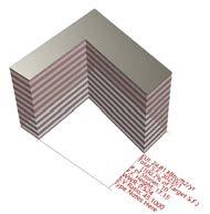
The different approaches we took revolved around changing multiple factors such as shape, number of “fingers,” orientation of the shape, window to wall ratio (WWR), and the number of stories. Due to the consistently nice weather of San Diego, there were only minor differences in the resultant EUI. Nevertheless, the changes in EUI are due to measurable and intentional alterations in the aforementioned variables. Some of the most significant changes in EUI were due to changes in orientation, and WWR; the minor differences were the results of changes in floor to floor height and number of stories. To further refine our collective studies for optimal EUI, we will focus the most on optimizing orientation, combined with the shape of the building, and then using other elements such as WWR and floor to floor height to cut down EUI as much as possible to reach the Target EUI associated with the site and building function of 18 kBtu/SF/yr.
SUMMARY
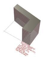
As seen in the images above, of the individual studies performed, there was little variation in EUI despite noticable differences in building orientations and widths. This, as explained in the team matrix page, has mostly to due with the very nice and consistent weather in San Diego. However, it can be noted the differences that account for the slight variations in EUI. One thing that was clear was that there was a clear correlation with a higher EUI, and more glazing exposed to the South. This intuitively makes sense, but it is backed up quantitatively with the EUI results. Furthermore, it was interesting that the U-shaped Typologies yielded the highest EUIs and S:V ratios, while the L-shaped study performed the best in terms of EUI, while having a lower S:V ratio. In an attempt to focus on form, the WWR, number of stories, and FF height remained constant throughout my studies.
PAGE 86 PAGE 87 LAB 02
INDIVIDUAL
LAB 02
ARCHITECTURAL SYSTEMS INTEGRATION 3.2
INDIVIDUAL STUDY 1
KIAH SPRAKER STACEY WHITE
SAN DIEGO, CA
300,000 SF 18 KBTU/SF/YR
LAB 02
ARCHITECTURAL SYSTEMS INTEGRATION 3.2
INDIVIDUAL STUDY 2
KIAH SPRAKER STACEY WHITE
SAN DIEGO, CA 300,000 SF 18 KBTU/SF/YR
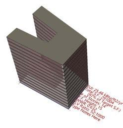
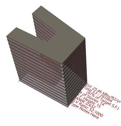
STUDY SUMMARY
TOTAL S.F.: 291,004 S.F. (97.0% OF TARGET S.F.)
# OF STORIES: 14
F.F. HEIGHT: 15
WWR: 0.632
S:V RATIO: 52:1000
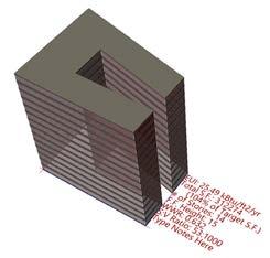
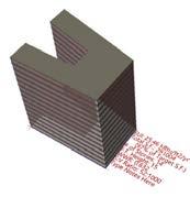
This building featues a U-shape typology that opens up towards the west. Whlie it could be worse for energy purposes (such as the U-shape opening towards the South), this form and orientation still yielded one of the highest EUIs out of all the studies. because of the minimal exterior walls, the WWR is relatively high, which is also a factor contributing to a higher EUI value. One thing that found interesting is the low S:V ratio relative to my other studies, since I would expect a form with more varied surfaces to feature a higher S:V ratio compared to a simpler form.
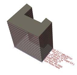
STUDY SUMMARY
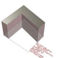
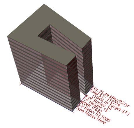
TOTAL S.F.: 312,274 S.F. (104% OF TARGET S.F.)
# OF STORIES: 14
F.F. HEIGHT: 14
WWR: 0.632
S:V RATIO: 53:1000
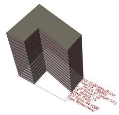
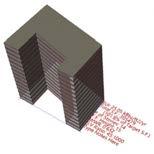
Similarly to the previous individual study, this building form features a U-shaped typology that opens up to the East this time. Something that I’m a little bit confused about is why this iteration features a higher EUI compared to the U-shaped building opening up to the West, which should technically get harsher sun each day in this site location. This could potentially be due to higher square footage of the building, or some other feature. The WWR was similar to the first study, at 53:1000, along with the FF Height and WWR, trying to maximize the entry of daylight into the building interior.
PAGE 88 PAGE 89
LAB 02
LAB
ARCHITECTURAL SYSTEMS INTEGRATION 3.2
INDIVIDUAL STUDY 3
KIAH SPRAKER
STACEY WHITE
SAN DIEGO, CA
300,000 SF 18 KBTU/SF/YR

LAB 03
ARCHITECTURAL SYSTEMS INTEGRATION 3.2


TEAM MATRIX
LILY SCHNEEBERGER
KIAH SPRAKER
STACEY WHITE SAN DIEGO, CA
300,000 SF 18 KBTU/SF/YEAR
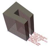
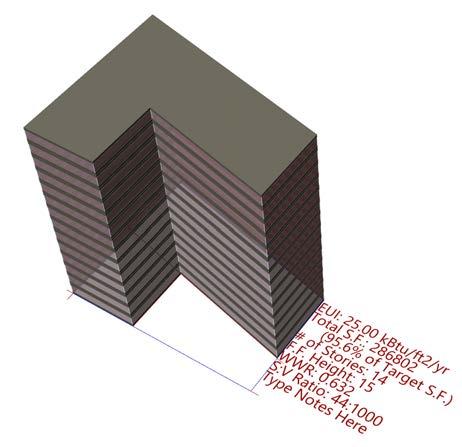
STUDY SUMMARY
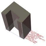
TOTAL S.F.: 286,802 S.F. (95.6% OF TARGET S.F.)
# OF STORIES: 14
F.F. HEIGHT: 15
WWR: 0.632
S:V RATIO: 44:1000
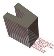
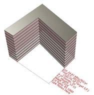
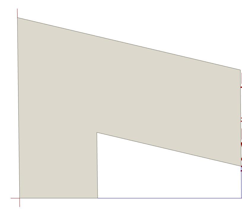
Unlike the previous two individual studies, this building features more of an L-shaped typology, with more of the western sun being blocked from entering the cut-in part in the South-East corner. Interestingluy, this building form and orientation featured the lowest EUI out of all my individual studies, and this is possibly due to the lower S:V Ratio (at 44:1000), or the smaller square footage of this one compared to the target. With the WWR and FF height, it is fair to say that this building form and orientation would yield more energy savings than the previous two options
SUMMARY
The different approaches we took revolved around changing multiple factors such as shape, number of “fingers,” orientation of the shape, window to wall ratio (WWR), and the number of stories. Due to the consistently nice weather of San Diego, there were only minor differences in the resultant EUI. Nevertheless, the changes in EUI are due to measurable and intentional alterations in the aforementioned variables. Some of the most significant changes in EUI were due to changes in orientation, and WWR; the minor differences were the results of changes in floor to floor height and number of stories. To further refine our collective studies for optimal EUI, we will focus the most on optimizing orientation, combined with the shape of the building, and then using other elements such as WWR and floor to floor height to cut down EUI as much as possible to reach the Target EUI associated with the site and building function of 18 kBtu/SF/yr.
PAGE 90 PAGE 91
02
ARCHITECTURAL SYSTEMS INTEGRATION 3.2
INDIVIDUAL MATRIX
KIAH SPRAKER STACEY WHITE SAN DIEGO, CA
300,000 SF 18 KBTU/SF/YEAR
LAB 03
ARCHITECTURAL SYSTEMS INTEGRATION 3.2
INDIVIDUAL SCHEME FOR LAB 3
KIAH SPRAKER STACEY WHITE
SAN DIEGO, CA
300,000 SF 18 KBTU/SF/YR
SUMMARY
As seen in the images above, of the individual studies performed, there was little variation in EUI despite noticable differences in building orientations and widths. This, as explained in the team matrix page, has mostly to due with the very nice and consistent weather in San Diego. However, it can be noted the differences that account for the slight variations in EUI. One thing that was clear was that there was a clear correlation with a higher EUI, and more glazing exposed to the South. This intuitively makes sense, but it is backed up quantitatively with the EUI results. Furthermore, it was interesting that the U-shaped Typologies yielded the highest EUIs and S:V ratios, while the L-shaped study performed the best in terms of EUI, while having a lower S:V ratio. In an attempt to focus on form, the WWR, number of stories, and FF height remained constant throughout my studies.
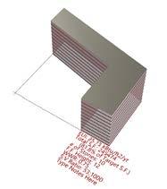
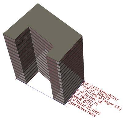
TOTAL S.F.: 305,479 S.F. (101.8% OF TARGET S.F.)
# OF STORIES: 14
F.F. HEIGHT: 15
WWR: 0.632
S:V RATIO: 45:1000
STUDY SUMMARY
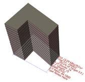
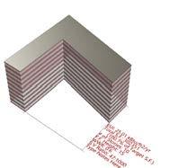
Open further analysis of EUI and program related studies after Lab 02, have decided to change my studies for Lab 03 to move forward with this two-finger typology with an opening towards the primary street face. This building featues a U-shape typology that opens up towards the South. Whlie it could be worse for energy purposes (such as the U-shape opening towards the South), this form and orientation yielded one of the lowest EUIs out of all the studies. Moreover, one aspect that could be contributing to a lower EUI is having less large faces of glass towards the South. Even so, the WWR is relatively high, with a large floor-to-floor height, which is contributing to the EUI not being as low as it could otherwise. One thing that I found interesting is the low S:V ratio relative to my other studies, since I would expect a form with more varied surfaces to feature a higher S:V ratio compared to a simpler form.
PAGE 92 PAGE 93
LAB 03
ARCHITECTURAL SYSTEMS INTEGRATION 3.2
DAYLIGHT STUDY
KIAH SPRAKER STACEY WHITE
SAN DIEGO, CA
300,000 SF
18 KBTU/SF/YR
ARCHITECTURAL SYSTEMS INTEGRATION 3.2
TWO-FINGER TYPOLOGY
With an overall building sDA value of 86%, the building is well above not only the minimum value of 55%, but even considerably over the preferred value of 75%. While this would ultimately be a balancing act between sDA, ASE, EUI, and other measurements, it is a good base to know that this form and orientation generates an sDA value that ensures plenty of access to daylight throughout the building. There are smaller (but not too small) “fingers” on the edges of the building for more individual focused programmatic spaces and a center that still receives plenty of daylight for larger public and community oriented functions.. In the back left away from direct access to sunlight would be an appropriate spot to place a core with spaces that don’t require access to daylight. An issue that would have to be addressed is glare especially coming in from the larger west face, which would have to be addressed with various shading devices.
OVERALL SDA VALUE OF 86% FOR THE BUILDING
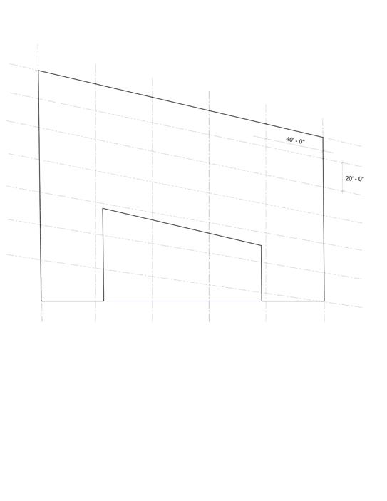
MASS TIMBER COLUMN GRID AND BAY SPACING
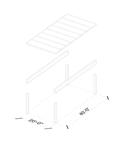
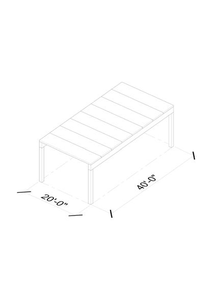
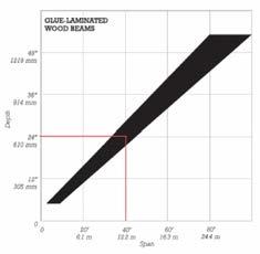
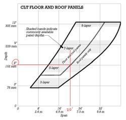
My intention for laying out the column grid and bay spacing revolved around balancing the often changing angles and dimensions of the building footprint, with trying to maintain regular grid dimensions and angles themselves. opted to angle the grid to follow the angle of the longest continuous face which defines the logic for the rest of the building. As seen in the charts and diagrams, wanted to maintain maximum head height with a floor to floor heigh of 15 feet, which was accomplished by using spans that did not push the material’s capacity to its limit. The span of 20’ in the short direction was in reference to the CLT panels’s standard spans, and being able to push the glulam beam length to 40’ which is well within its capabilities.
PAGE 94 PAGE 95
03
LAB
5 LAYER CLT PANELS
24” DEEP GLUAM BEAMS
15’ 0”
LAB 03
ARCHITECTURAL SYSTEMS INTEGRATION 3.2
ARCHITECTURAL SYSTEMS INTEGRATION 3.2
Walls and Floors lined with yellow paper for a blurring effect of vertical and horizontal space and color
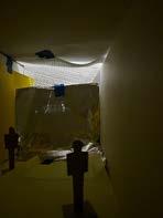
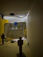
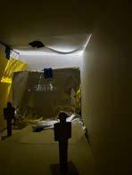

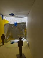

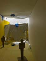
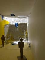
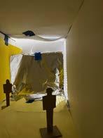
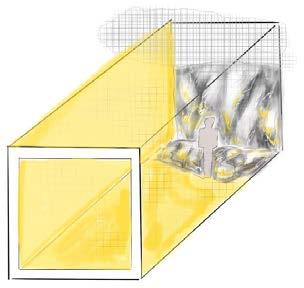
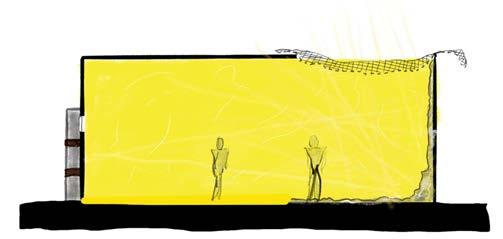
Perforated drooping material bringing in patterned rays of daylight.
Aluminum foil randomly spreading the patterned daylighting throughout the space
PAGE 96 PAGE 97 LAB 04
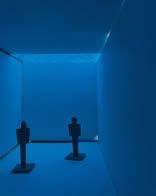
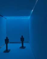
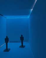
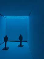
2023 LAB 04 WINTER SOLSTICE SPRING/AUTUMN EQUINOX SUMMER SOLSTICE 9 AM 12 PM 3 PM 9 AM 12 PM 3 PM 9 AM 12 PM 3 PM Mood 1 MEDITATIVE
Kiah
Spraker | Stacey White | Winter
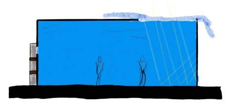
2023 LAB 04 WINTER SOLSTICE SPRING/AUTUMN EQUINOX SUMMER SOLSTICE 9 AM 12 PM 3 PM 9 AM 12 PM 3 PM 9 AM 12 PM 3 PM Mood 2: CAPTIVATING
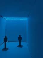
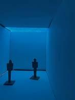
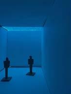
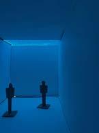
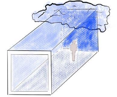
Blue Tissue paper over small gap in the roof creating a soft, even, ambient blue glow througout the space
Kiah Spraker | Stacey White | Winter
LAB 04
ARCHITECTURAL SYSTEMS INTEGRATION 3.2
ARCHITECTURAL SYSTEMS INTEGRATION 3.2
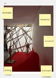
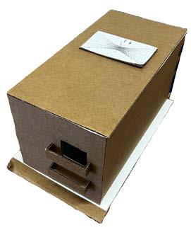

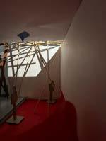
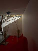
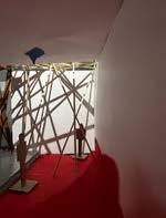
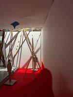
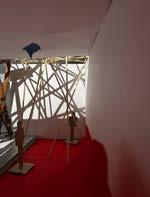
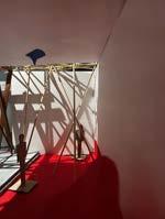
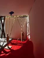
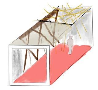
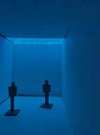
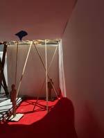
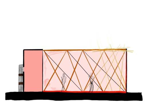
A. Space and its perception are fundamental in architecture, and the manipulation of said space through light and architectural features have been thoroughly explored in my explorations in this lab. In my first mood exploration, studies have shown that a blue lit space free from distractions is ideal for practicing meditation. This experience is explored in my space through using blue tissue paper to serve as a light filter without intruding on the space within. This ambient experience can be enjoyed by the occupants in any manner, but is ideal for a calm, meditative state of being. In my second mood exploration, used a variety of means to manipulate light and space to create a space that was captivating to its occupants. This is done primarily through the use of a perforated material which lets patterned daylight hit a sheet of aluminum foil that bends from the wall to the floor to blur the real confines of the space. Furthermore, the walls lined with yellow paper further blur the boundaries of the space while also helping to reflect the randomly reflecting light throughout the space. In my third exploration, using the most unique materials and techniques to aid in my exploration, created a dramatic atmosphere using a series of intense intersecting shadows combined with larger organizing shadows from braced frames lining the side wall. With the aid of a red floor to inspire this dramatic mood, the occupants can’t help but be engulfed in the dramatic flare of the room.
Success!!
B. Light is extremely important in my studio project not only from a programmatic sense with the need for residential and office space, but also in the idea of integrating a large amount of greenery with a vertical park spreading throughout the entirety of my project. In the office spaces specifically, in their current layout be mostly found in the southern and western parts of the building, extra attention must be taken to ensure that the office spaces aren’t receiving any harsh direct light or light full of fritts or patterns that could distract the occupants or introduce unnecessary glare. This could be accomplished through shading devices that evenly spread the light across the office space such as large light shelves on the south and western facades in the upper half of the glazing on the apertures. Further and similar attention will be brought to the residential spaces, ensuring that all of the units are receiving similar and high quality daylighting to take away from the need to depend on electric lighting for any of the day.
PAGE 98 PAGE 99
LAB 04 WINTER SOLSTICE SPRING/AUTUMN
SUMMER SOLSTICE 9 AM 12 PM 3 PM 9 AM 12 PM 3 PM 9 AM 12 PM 3 PM
Kiah Spraker | Stacey White | Winter 2023
EQUINOX
Mood 3: DRAMATIC
Sticks organized at random angles in all three dimensions to create for dynamic light experiences Semi-open wall framed by braced frames that create bold, organizing shadows inside
LAB 04
Red paper on the ground setting the dramatic mood of the space
LAB 04
Kiah Spraker | Stacey White | Winter 2023
REFLECTION
LAB 04
Mood-Mapping Artifact
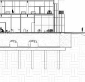
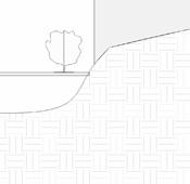
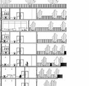
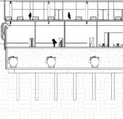
INTEGRATED BUILDING SECTION
ARCHITECTURAL SYSTEMS INTEGRATION 3.2
PROJECT MANUAL


ARCHITECTURAL SYSTEMS INTEGRATION 3.2


ACTIVE SYSTEMS PHOTOVOLTAIC PANELS ON ROOF TO PRODUCE ONSITE ENERGY AND REDUCE NEED FOR MUNICIPAL ENERGY USAGE
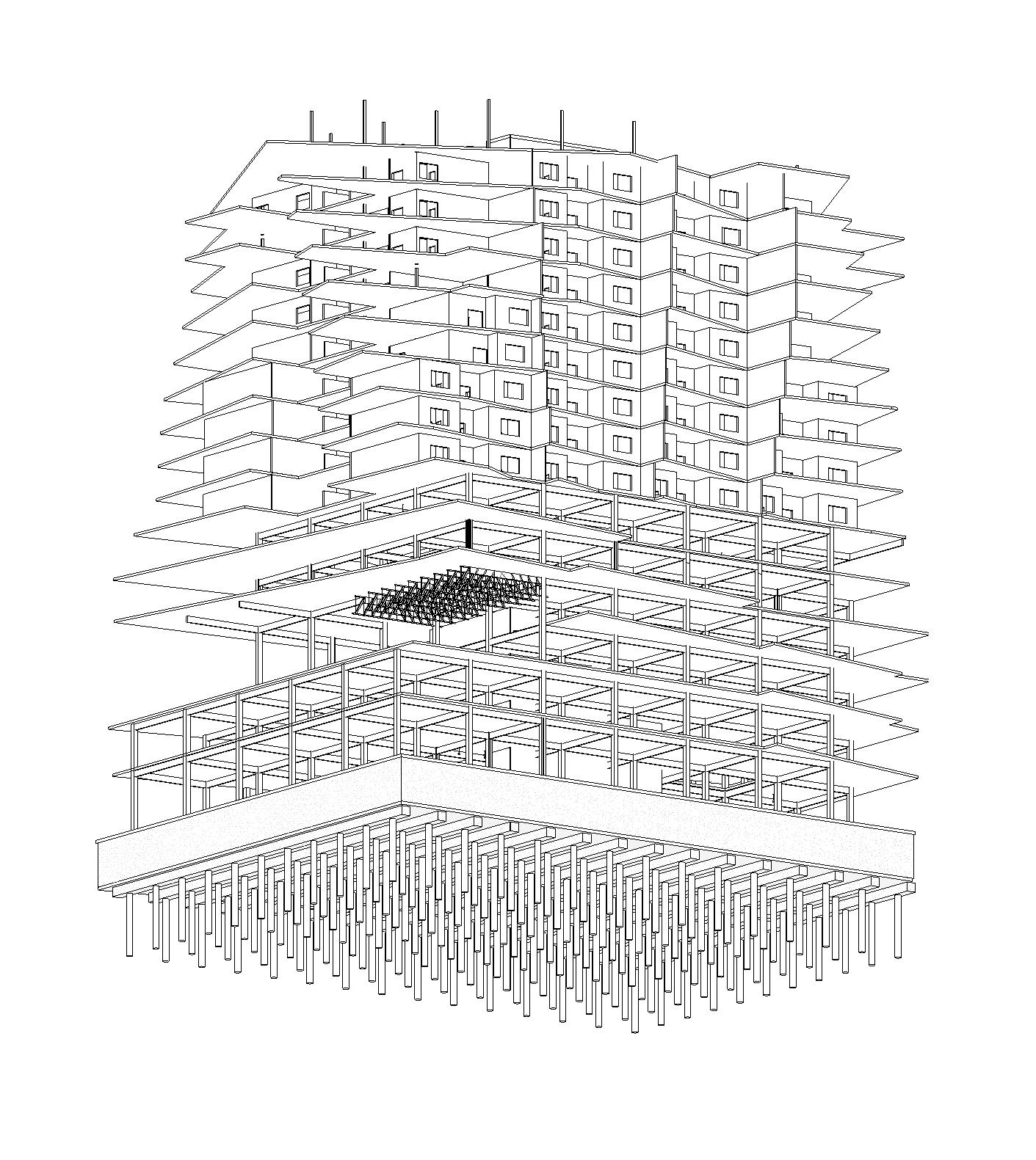
STRUCTURAL SYSTEM
SOLSTICE
PASSIVE COOLING BALCONIES FOR SHADING AND ACCESS TO PROTECTED GREEN SPACE
SPATIAL EXPRESSION

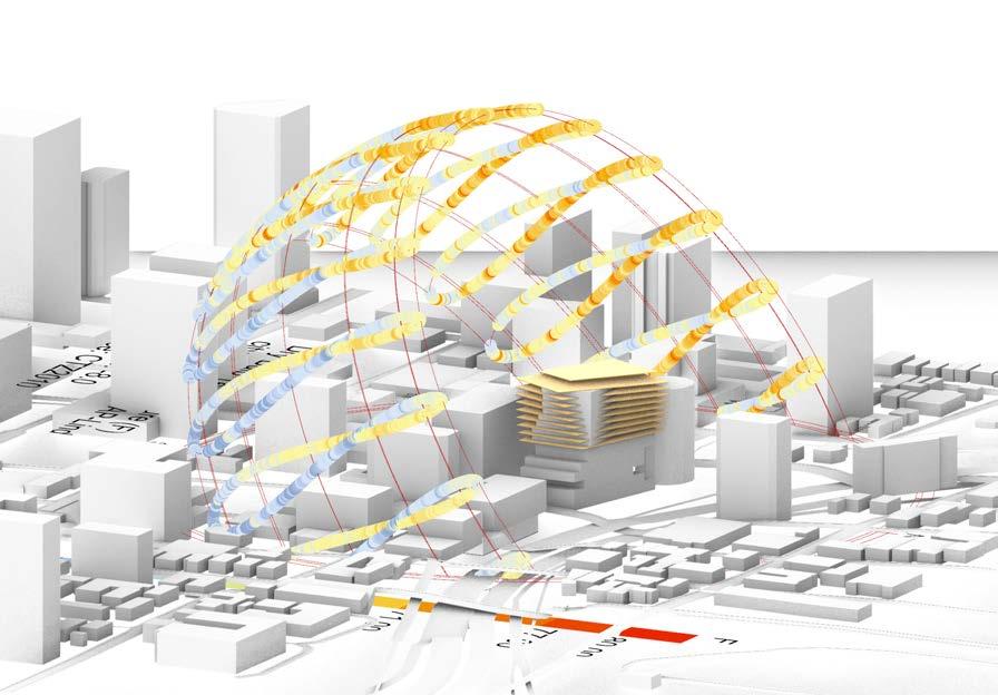
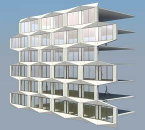
ROTATING FORM FLOOR BY FLOOR ALLOWS FOR DYNAMIC DAYLIGHTING POTENTIAL AND EQUAL ACCESS TO SURROUNDING VIEWS

MECHANICAL SYSTEMS AIR-BASED SYSTEM FOR PUBLIC FLOORS AND RADIANT SYSTEM FOR PRIVATE RESIDENTIAL FLOORS
STRUCTURE | Level 7-15
MASS TIMBER
7 LAYER CLT FLOOR SLAB
8"x8" GLULAM COLUMNS LOAD BEARING CLT PARTITION WALLS
NATURAL VENTILATION PREVAILING WIND FROM NW REACHING A MAXIMUM OF 20 MPH
STRUCTURE | Level 1-6
Glulam trusses to support long span outdoor area
SPATIAL EXPRESSION HIGH FLOOR TO FLOOR
MASS TIMBER
7 LAYER CLT FLOOR SLAB
24" DEEP GLULAM BEAMS
18"x18" GLULAM COLUMNS
Central CLT core providing vertical and laterial stability
Levels 7-15: 7 Layer CLT slab with 8” x 8” CLT Columns and load-bearing CLT partition walls
STRUCTURE | BELOW GRADE REINFORCED CONCRETE WITH

16"X16" PILES @ 14' O.C
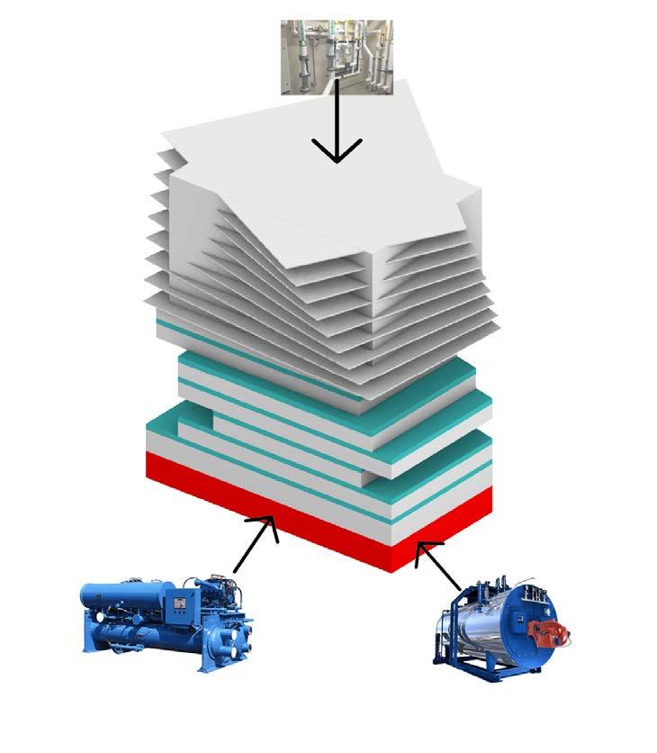
ACTIVE SYSTEMS CENTRAL PLANT PROVIDING HOT AND CHILLED
WATER TO THE ENTIRE CAL WESTERN CAMPUS
Levels 1-6: 7 Layer CLT slab with 18” x 18” CLT columns and 24” deep Glulam Girders and Glulam beams
Concrete Pile foundation spaced @14’ Each Way
Reinforced Concrete Levels below grade
PAGE 100 PAGE 101
203'-0" 191'-0" 179'-0" 167'-0" 155'-0" 143'-0" 131'-0" 119'-0" 107'-0" 95'-0" 80'-0" 65'-0" 50'-0" 35'-0" 20'-0" 1' 5' 10' 20' SUMMER
12:00
80.91° WINTER
12:00 PM 34.53°
SOLSTICE
PM
HEIGHTS AND OPEN CIRCULATION IN PUBLIC FLOORS TO ENCOURAGE INTERACTION, AND IMPROVED DAYLIGHTING AND VENTILATION PASSIVE SYSTEMS GREEN ROOF TO REDUCE HEAT ISLAND EFFECT AND SERVE AS RAINWATER COLLECTION FOR GREY WATER USE IN BUILDING INTERFACE N KIAH SPRAKER | STUDIO WHITE | WINTER 2023
PROJECT MANUAL
ARCHITECTURAL SYSTEMS INTEGRATION 3.2
DAYLIGHT STRATEGIES
PROJECT MANUAL
ARCHITECTURAL SYSTEMS INTEGRATION 3.2
HVAC SYSTEM
Plumbing Chaise in central core for efficient circulation of water for plumbing and mechanical systems throughout the building
Overhanging balconies providing shading from harsh direct sunlight from the South and West primarily
Levels 7-15: Hydronic system distributing hot/ cold water from central plant and throughout floors with radiant system of pipes Levels 1-6: Air-based system distributed through ducts in the ceilings
Slight rotation of floor plates moving up building mimics movement of the sun, allowing for maximum daylighting Extra Daylighting strategies not needed on lower floors due to shading from neighboring buildings.

Source:
Central plant with Boilers and Chillers providing hot and chilled water to this building and the other three buildings for the proposed Cal Western Law School Campus
PAGE 102 PAGE 103
PROJECT MANUAL
ARCHITECTURAL SYSTEMS INTEGRATION 3.2
SOLAR RESPONSE
PROJECT 01

ARCHITECTURAL SYSTEMS INTEGRATION 3.3
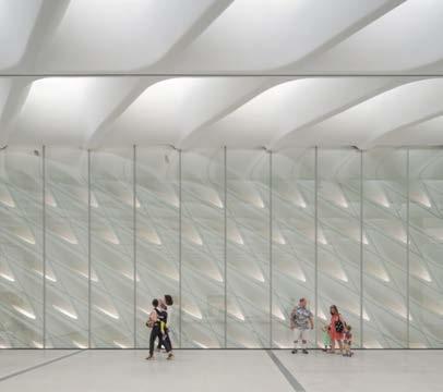
The Broad Museum
Architects: Diller Scofidio + Renfro Project Size: 120,000 SF Location: Los Angeles, CA
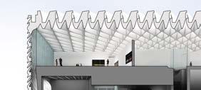
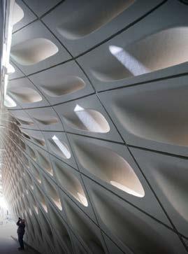
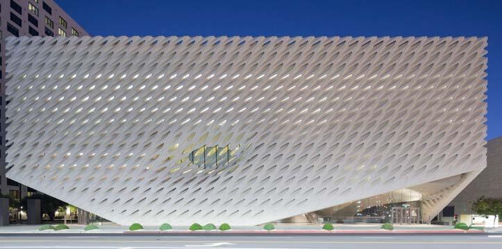
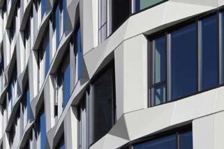
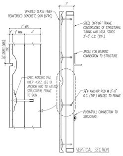
Material Exploration: Glass-Fiber Reinforced Concrete (GFRC)
The GFRC in the Broad museum is serving as the exterior portion of a double skin facade with the inner portion being mostly curtain wall glazing. The material is parametrically customized to respond to daylighting conditions necessary for an art museum and allows for the spatial characteristics required for circulation and spatial arrangements. The color of the material is its natural white color that results from the material itself. The texture is mostly smooth from careful prefabrication of the units that are combined together to form this GFRC envelope. As seen in the diagrammatic section below, GFRC is able to be highly customized and designed to fit its desired function
PAGE 104 PAGE 105 Summer Solstice: 12:00 pm 80.91° Winter Solstice: 12:00 pm 34.53°
KIAH SPRAKER | STUDIO WHITE | SPRING 2023
All Photographs: © Iwan Baan. “The Broad Museum / Diller Scofidio + Renfro.”2015. ArchDaily. Accessed April 23, 2023. https://www.archdaily.com/772778/ the-broad-diller-scofidio-plus-renfro
“The Broad Museum / Diller Scofidio + Renfro.”2015. ArchDaily. Accessed April 23, 2023. https://www.archdaily.com/772778/ the-broad-diller-scofidio-plus-renfro
PROJECT 01
ARCHITECTURAL SYSTEMS INTEGRATION 3.3
PROJECT 01
ARCHITECTURAL SYSTEMS INTEGRATION 3.3
Contra Costa Administration Building
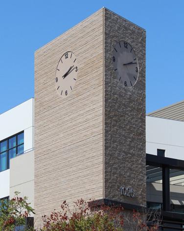
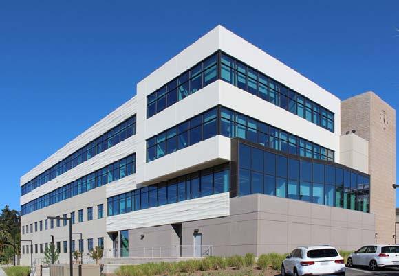
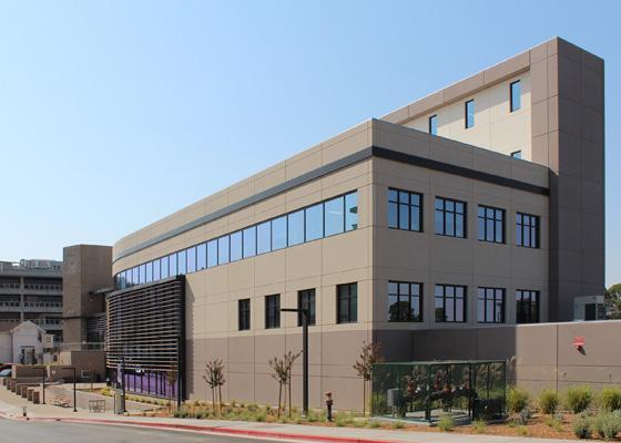
Architects: Fentress
GFRC Facade SF: 35,000
Location: Martinez, CA
Material Exploration: Glass-Fiber Reinforced Concrete (GFRC)
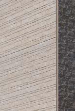
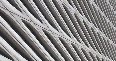
This government building used primarily GFRC for the facade with it serving several functions and aesthetics. Do to its mold-able and customizable characteristics, and its ease of construction, GFRC was used to replicate a historic stone texture in the clock tower, taking on the color of stone as well. Furthermore, in a more modern aesthetic, using CAD, the architects designed a “wave”texture for a portion of the facade which was constructed using specially designed fiber glass molds and then put together in a panelized system that was hung from the primary structure
Serif and The Line Hotel
Architects: Handel Architects
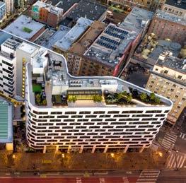
Project Size: 81,500
Location: San Francisco, CA
Material Exploration: GFRC
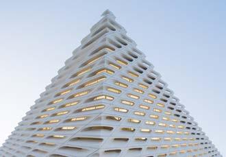
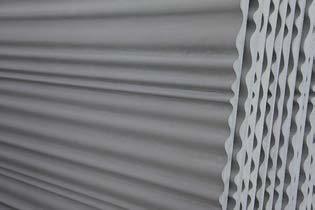
This mixed-use hotel and residential building has an irregular, geometrically complex shape, which led to the selection of GFRC due to its customizable shape, color and texture. Its smooth texture and geometric shapes were pre-cast into 583 total panels which wrap around the flat and curved portions of the building creating a dynamic facade that aids in shading and unifying the building aesthetic. Unlike other projects where the GFRC is dominant in the facade, here it serves as a more interesting and architectural opaque frame to glazing in this high WWR facade. Like most other panelized facade products, the front extrudes out in various geometric patterns, but the back is flat and hung on the
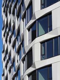
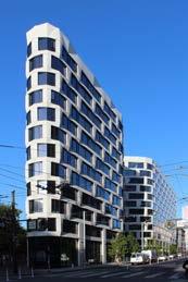
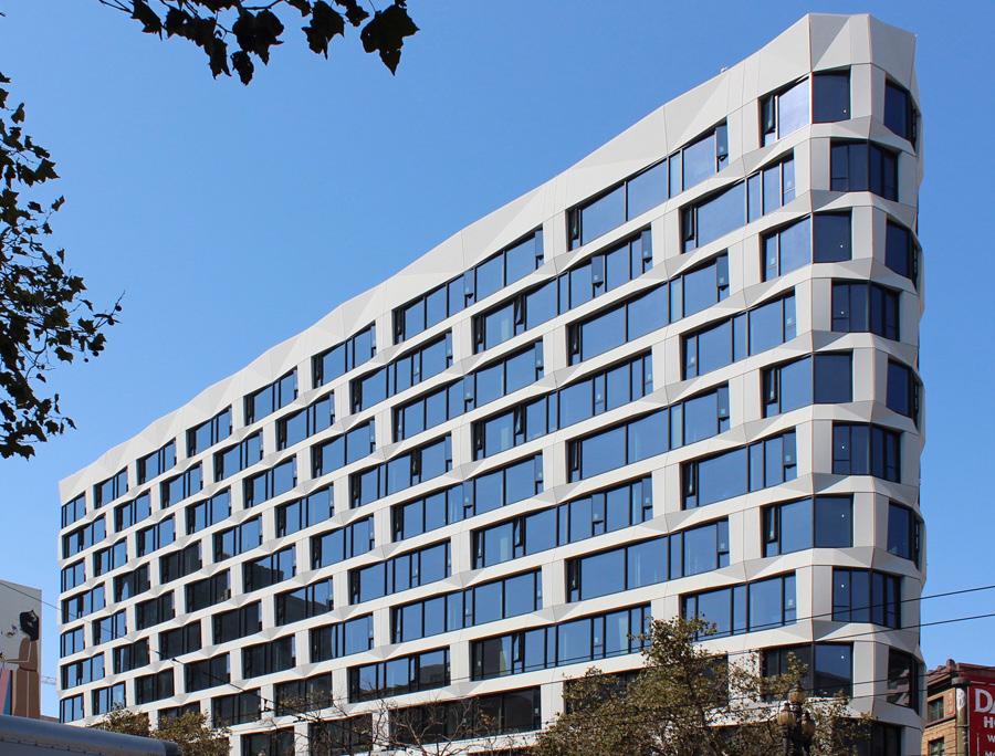
behind

PAGE 106 PAGE 107
KIAH SPRAKER | STUDIO WHITE | SPRING 2023
All Photographs and Information: ©Willis Construction Co. Inc. “Contra Costa Administration Building.”2022. Willis Construction Co. Inc Accessed April 23, 2023. http://www.pre-cast.org/contra-costa.asp#prettyPhoto
KIAH SPRAKER | STUDIO WHITE | SPRING 2023
primary structure
All Photographs and Information: ©Willis Construction Co. Inc. “Serif and The Line Hotel At 950 Market Street.” 2022. Willis Construction Co. Inc Accessed April 23, 2023. https://handelarchitects.com/project/950-market-street-hotel-residences
PROJECT 01
ARCHITECTURAL SYSTEMS INTEGRATION 3.3
GLASS FIBER REINFORCED CONCRETE
(GFRC)
PROJECT 01
ARCHITECTURAL SYSTEMS INTEGRATION 3.3
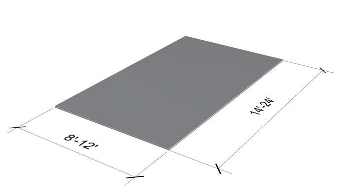
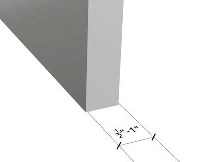
Dimensions limited by transportation sizes and molds
Dimensions displayed respond to simple transportation sizes and ease of constructibility GFRC Panels often are made smaller, but displayed dimensions represent typical maximum sizes from common constraints

PAGE 108 PAGE 109
KIAH SPRAKER | STUDIO WHITE | SPRING 2023
SCALE: 1/2” = 1’-0” KIAH SPRAKER STACEY WHITE APRIL 25, 2023
WALL SECTION SCALE: 1/2” = 1’-0” KIAH SPRAKER STACEY WHITE APRIL 25, 2023
WALL ELEVATION KIAH SPRAKER | STUDIO WHITE | SPRING 2023
GFRC
GFRC
PROJECT 01
ARCHITECTURAL SYSTEMS INTEGRATION 3.3
GFRC CSI SPECIFICATION SUMMARY (SECTION 03455)
MANUFACTURERS:
• Willis Construction Co.
• Stromberg Architectural Products
• GFRC Cladding
• TerraGlas
Other Materials From “Related Sections”:
• Architectural Precast Concrete - common for similar uses for cladding and wall products
• Masonry Veneer - another material like GFRC used primarily for exterior finishes/aesthetics and not for structural reasons
• Granite - another siding material for a different aesthetic than GFRC
• Structural Steel - can be used as the primary structure in which GFRC can attach to
Choices Needed to Make and Questions:
• In order to add color to the GFRC during mixing, I first must decide what color fits with the aesthetic of the building and environment, which also brings the question of how to find a color that not only is harmless to people or the product, but also fits within the context and concept of the building?
• It is more standard providing connection from GFRC to concrete or steel, but how do the connections work for attaching to mass timber so the same structural integrity is reached as in steel or concrete?
• Is it possible to use a light wood frame stud system for fabrication and erection rather than the specified steel stud welded frame to offer a more sustainable and low energy solution?
PROJECT 01
ARCHITECTURAL SYSTEMS INTEGRATION 3.3
SECTION 03455 - Glass Fiber Reinforced Concrete (GFRC)
1. GENERAL 1.1 DESCRIPTION
A. Section Includes
1. Structural design and detailing of panels (products).
2. Plant fabrication of glass fiber reinforced concrete (GFRC) panels.
3. Transportation of GFRC panels to job site.
4. Installation (erection) of GFRC panels.
B. Related Documents The requirements of the General Conditions, Supplementary General Conditions and applicable portions of Division 1 of these Specifications as they apply to this Section.
C. Related Sections :
1. Section 03450 - Architectural Precast Concrete
2. Section 03300 - Cast-In-Place Concrete
3. Section 04255 - Masonry Veneer
4. Section 04455 - Marble
5. Section 04465 - Granite
6. Section 05120 - Structural Steel
7. Section 05500 - Metal Fabrications
8. Section 07210 - Building Insulation
9. Section 07270 - Firestopping
10. Section 07600 - Flashing and Sheet Metal
11. Section 07920 Sealants and Caulking
12. Section 08800 - Glazing
13. Section 09300 - Tile
1.2 REFERENCES
A. Uniform Building Code, 1997 Edition.
B. PCI MNL-128-01 GFRC Recommended Practice for Glass Fiber Reinforced Concrete Panels, Fourth Edition
C. PCI MNL-130 - Manual for Quality Control For Plants and Production of Glass Fiber Reinforced Concrete Products, Second Edition
D. AWS D1.1-98 : Structural Welding Code - Steel
E. AWS D1.3-89 Structural Welding Code - Sheet Steel
F. AWS D1.4-92 Structural Welding Code - Reinforcing Steel
G. ASTM A27 Steel Castings, Carbon, for General Application
H. ASTM A36 : Structural Steel
I. ASTM A47 Ferritic Malleable Iron Castings
J. ASTM A53 : Pipe, Steel, Black and Hot-Dipped, Zinc-Coated Welded and Seamless
K. ASTM A108 : Steel Bars, Carbon, Cold-Finished, Standard Quality
L. ASTM A123 : Zinc Coatings on Iron and Steel Products
M. ASTM A153 Zinc Coating (Hot-Dip) on Iron and Steel Hardware
N. ASTM A307 : Carbon Steel Bolts and Studs, 60,000 Tensile Strength
O. ASTM A325 Structural Bolts, Heat Treated, 120/105 ksi Minimum Tensile Strength
P. ASTM A446 : Steel Sheet, Zinc-Coated (Galvanized) by the Hot-Dip Process, Structural (Physical) Quality
Q. ASTM A449 Quenched and Tempered Steel Bolts and Studs
R. ASTM A496 : Steel Wire, Deformed, for Concrete Reinforcement
S. ASTM A500 : Cold-Formed Welded and Seamless Carbon Steel Structural Tubing in Rounds and Shapes
T. ASTM A513 : Electric-Resistance-Welded Carbon and Alloy Steel Mechanical Tubing
U. ASTM A525 : Sheet Steel, Zinc-Coated (Galvanized) by the Hot-Dip Process
PAGE 110 PAGE 111
KIAH SPRAKER | STUDIO WHITE | SPRING 2023
PROJECT 01 ARCHITECTURAL SYSTEMS INTEGRATION 3.3
V. �
W. ASTM A563 Carbon and Alloy Steel Nuts
X. ASTM A570 Steel, Sheet and Strip, Carbon, Hot-Rolled, Structural Quality
Y. ASTM A572 High-Strength Low-Alloy Columbium-Vanadium Structural Steel
Z. ASTM A615 : Deformed and Plain Billet-Steel Bars for Concrete Reinforcement
AA. ASTM A706 : Low-Alloy Steel Deformed Bars for Concrete Reinforcement
AB. ASTM B633 : Electrodeposited Coatings of Zinc on Iron and Steel
AC. ASTM B766 : Electrodeposited Coatings of Cadmium
AD. ASTM C33 Concrete Aggregate
AE. ASTM C150 : Portland Cement
AF. ASTM C260 Air-Entraining Admixtures for Concrete
AG. ASTM C494 : Chemical Admixtures for Concrete
AH. ASTM C618 : Fly Ash and Raw or Calcined Natural Pozzolan for Use as a Mineral Admixture in Portland Cement Concrete
AI. ASTM C979 : Pigments for Integrally Colored Concrete
AJ. SAE J429 : Mechanical and Material Requirements for Externally Threaded Fasteners
AK. DOD-P-21035
1.3 SYSTEM DESCRIPTION
A. Plant fabricated GFRC panels consisting of face mix, back-up mix, steel support frame attached via pins, gravity anchors and flex anchors, steel connections for panel attachment to structure, and other inclusions for attachments to panels. Panels are transported to the job site for installation.
B. GFRC panel fabrication shall include all labor, materials, and equipment necessary to manufacture the panels as shown by the Contract Documents.
C. GFRC panel installation shall include all labor, materials, and equipment necessary for the installation of the panels as shown by the Contract Documents.
D. The GFRC Manufacturer shall design and furnish all GFRC connection hardware to be attached to or embedded in the panels; shall furnish all loose connection hardware, and shall furnish all connection hardware required to be embedded in the cast-inplace concrete for connection of the GFRC panels. The placement of the hardware in the cast-in-place concrete will be the responsibility of the General Contractor.
E. Hardware which is to be incorporated into the fabrication of the GFRC panels for other trades shall be provided to the GFRC Manufacturer, with instructions, in a timely manner in order not to disrupt or delay production. All such hardware shall be fully defined in contract drawings.
F. When required by the Contract Documents, the GFRC Manufacturer shall design, furnish, and install steel preweld required (such as outriggers and downriggers) to carry the loads from the GFRC panels to the structure. Any additional bracing or stiffening of the structure required to support the loads from the GFRC panels shall be by others unless specifically shown on the contract drawings by the Precast Manufacturer.
1.4 QUALIFICATIONS
A. Design GFRC panels shall be designed under the supervision of a civil engineer registered in the State of California employed or retained by the GFRC Manufacturer, using property data generated from the Manufacturer's actual production and in accordance with procedures in Precast/Prestressed Concrete Institute (PCI) "Recommended Practice for Glass Fiber Reinforced Concrete Panels", MNL-128. All design loads shall meet the requirements of the Uniform Building Code.
B. Manufacturing The GFRC manufacturing plant shall be certified at the time of bid by the Precast/Prestressed Concrete Institute Plant Certification Program for Group G.
Acceptable Manufacturers
1. Willis Construction Co. Inc.
2. �
C. Erector : Regularly engaged for at least 5 years in erection of GFRC panels similar to those required on this project. The present erection management team shall be capable of installing the required panels without causing delay of project schedules.
D. Welders (Shop, Plant and Field) : Welders performing work under this specification shall be
PROJECT 01 ARCHITECTURAL SYSTEMS INTEGRATION 3.3
qualified in accordance with AWS D1.1, AWS D1.3 and AWS D1.4 as required to perform work at all stages of production and erection.
E. Testing GFRC Manufacturer shall comply with the testing provisions in MNL-130, Manual for Quality Control of Plants and Production of Glass Fiber Reinforced Concrete Products.
1.5 SUBMITTALS
A. Submit all information under provisions of Division 1.
B. Samples
1. Submit preliminary samples, approximately 12" by 12", representative of finished exposed face.
2. Prior to commencement of manufacture, submit production samples, approximately 4' x 4', for final approval of colors and textures.
C. Shop and Erection Drawings : Submit one (1) reproducible set and 3 blueline sets showing;
1. Material specifications,
2. Floor plans identifying location of panels,
3. Floor plans identifying location of pre-erection attachments (i.e. cast-in-place embed and prewelds) to supporting structure,
4. Elevations identifying location of panels and their connections,
5. Details as necessary to describe relationship of panels to adjacent material,
6. Details of panel connections,
7. Description of all hardware attached to panel frames, sent loose to the job site, and cast into or attached to supporting structure,
8. Elevations and sections of typical panels showing;
a. geometry and finish,
b. thickness of face and back-up mixes,
c. steel frame members and dimensions,
d. size, location and details of flex and gravity anchors,
e. other items sprayed into panels,
f. points for stripping, lifting, and erection,
g. connection hardware with piece marks and their location on the steel frame,
h. embed locations for attachment where frame is not provided.
D. Mix Designs Submit all GFRC mix designs for approval. Mix designs shall be prepared by an independent testing facility or qualified employee of the GFRC Manufacturer.
E. Weld Procedure Specifications Submit Welding Procedure Specifications in accordance with AWS D1.1, D1.3 and D1.4 requirements for all welding which will be performed under this Section.
F. Design Calculations : Submit complete design calculations for governing panel types and connections including loads used in design.
G. Design Modifications :
1. Submit design modifications necessary to meet performance requirements and field conditions.
2. Variations in details or materials shall not adversely affect the appearance, durability or strength of panels.
3. Maintain general design concept without altering size of members, profiles and alignment unless otherwise approved by the Architect/Engineer.
4. �
H. Test Reports :
1. Submit, upon request, all GFRC backing and anchor test data on which GFRC design is based.
2. Submit, upon request, test reports required in Section 1.1.6B.6.
1.6 QUALITY ASSURANCE
A. Full-Scale Panel :
1. After standard samples are accepted for color and texture, produce full-scale panel meeting design requirements. This panel shall be viewed and approved by the Architect at the GFRC plant.
2. The full-scale panel shall be representative of standard quality for GFRC panel work, when accepted by Architect.
3. Incorporate full-scale panel into work after keeping panel in plant for checking purposes.
B. In-Plant Quality Control
PAGE 112 PAGE 113
PROJECT 01
ARCHITECTURAL SYSTEMS INTEGRATION 3.3
1. The GFRC Manufacturer shall have an established PCI quality control program in effect prior to bidding. If requested, a copy of this program shall be submitted to the Architect.
2. Testing of materials and inspection of production techniques shall be the responsibility of the GFRC Manufacturer’s Quality Control Department.
3. A quality control program shall be in effect to monitor glass content, spray rate, panel weight, product physical properties, anchor pull-off and shear strengths, and curing periods and conditions. Results of such quality control tests and evaluation of such tests shall be submitted to the Architect upon request.
4. Preparation of the test specimens and test procedures shall be in accordance with PCI MNL-130 and MNL-128, Chapter 8 - Quality Control.
5. Panel manufacturer shall test inserts and anchors that are embedded in GFRC panels to establish values for use in design.
6. Test boards shall be produced at the rate of one per work shift per operator for each spray machine and each mix design, as a minimum. For each test board, determine;
a. Glass content by "Wash-out test".
b. Flexural yield and ultimate strength.
7. Keep quality control records available for two years after final acceptance.
8. Keep certificates of compliance available for five (5) years after final acceptance.
C. All other testing and inspection to be provided by Owner.
2. PRODUCTS 2.1 GLASS FIBER REINFORCED CONCRETE MATERIALS
A. Portland Cement
1. Architectural Mixes : ASTM C150 Type I, II or III cement. For surfaces exposed to view in the finished structure use same brand, type and source of supply throughout the GFRC production.
2. Back-up Mixes Back-up mix shall be compatible with the architectural mix to which it is combined.
B. Aggregates
1. Architectural Mixes Fine and coarse aggregate for face mix shall conform to ASTM C33 except for gradation. Aggregates shall be clean, hard, strong, durable, inert, and free of staining and deleterious materials.
2. Back-up Mixes : Sand for GFRC backup shall be washed and dried silica, or approved equal, with a history of successful use in GFRC. All sand shall pass through a No. 20 (850µm).
C. Water Free from deleterious matter that may interfere with the color, setting, or strength of the concrete.
D. �
PROJECT 01
ARCHITECTURAL SYSTEMS INTEGRATION 3.3
D. Sheets and Strips (less than 3/16")ASTM A570 Grade 36
E. Reinforcing SteelASTM A615 Grades 40 & 60 or ASTM A706
F. Deformed Bar AnchorsASTM A496
G. Welded Headed StudsAWS D1.1 Type B
H. Standard Machine BoltsASTM A307 Grade A or SAE J429 Grade 2
I. Standard Studs/Threaded Round Stock (UNC) … ASTM A307 Grade C, ASTM A572 Grade 50
J. Nuts for Standard Machine Bolts and Threaded Studs … ASTM A563 Grade A Hex Nuts
K. High Strength Machine Bolts … ASTM A325 Type 1, ASTM A449 Type 1, or SAE J429 Grade 5
L. Nuts for High-Strength Machine Bolts and Threaded Studs … ASTM A563 Grade A Heavy Hex Nuts
M. Coil Rods and BoltsASTM A108 - SAE 1016 to 1026, F u /F = 70/55 ksi minimum
N. Coil Nuts for Coil Rods and Bolts … Nuts passing a proof load stress of 80 ksi, based on the tensile stress area of the matching coil rods and bolts.
O. Malleable Iron CastingsASTM A47 Grade 32510
P. Carbon Steel CastingsASTM A27 Grade 60-30
Q. GFRC Pins (cold drawn wire) . . . ASTM A108 - SAE 1006 to 1012 with Supplementary Requirement S1.
R. Track and Studs :
1. Rust Inhibitive CoatedASTM A570 Grade 50
2. GalvanizedASTM A446 Grade A, coating designation 60
2.3 STEEL PROTECTIVE COATINGS : All thin gauge material (that less than 3/16" thick) shall have either a alkyd rust inhibitive primer or zinc coating (see below). All steel materials in contact with the GFRC skin or exposed to weather shall have a zinc coating. Loose attachment hardware equal to or greater than 3/16" thick need not be coated if not exposed to weather. Fasteners can have either an electroplated zinc or cadmium coating.
A. Alkyd Rust Inhibitive Primers (shop primers such as red iron oxide)
1. Tnemec Series FD88 Azeron Primer
2. Ameron 5105
3. Substitutions : Under provisions of Division 1.
B. Zinc Coatings
E. Admixtures Conforming to ASTM C260, ASTM C494, ASTM C618 or acrylic thermoplastic copolymer dispersion conforming to PCI MNL-130, Appendix E.
F. Coloring Agent: Conforming to ASTM C979.
1. Shall be harmless to GFRC set and strength.
2. Shall be stable at high temperature.
3. Shall be alkali-resistant.
G. Glass Fiber Conforming to PCI MNL-130, Appendix D.
1. Fibers with a minimum of 16 percent zirconia specifically designed to be compatible with the aggressive alkaline environment of Portland cement based composites.
2. Fabricator shall submit upon request evidence that the glass composition has been designed for glass fiber reinforced concrete applications.
2.2 STEEL PRODUCTS
A. Structural Shapes, Bars & Plates (1/8" and thicker)ASTM A36
B. PipeASTM A53 Grades A or B
C. Tube SteelASTM A500 Grades A or B
1. Hot-Dip GalvanizingASTM A123, or ASTM A153
2. Hot-Dip Galvanized for Steel SheetASTM A525
3. Electroplated Zinc for Steel Products and Steel HardwareASTM B633
4. Zinc Rich PaintsDOD-P-21035
C. Cadmium Coatings :
D. �
1. Electrodeposited Coatings of CadmiumASTM B766
2.4 FABRICATION
A. GFRC Manufacturer shall not proceed with fabrication of panels prior to receiving the reviewed set of Shop Drawings and the Architect’s acceptance of submitted Samples.
B. Manufacturing procedures shall be in general compliance with PCI MNL-130.
C. Batching of Face and Backup Mixes :
1. All measurements of mix constituents shall be carried out in a careful manner to achieve the desired mix proportions.
PAGE 114 PAGE 115
PROJECT 01
ARCHITECTURAL SYSTEMS INTEGRATION 3.3
2. The glass fiber and cement slurry shall be metered at rates to achieve the desired mix proportions and glass content. These shall be checked in accordance with standard procedures described in PCI MNL-130.
3. Cleanliness of equipment and working procedure shall be maintained at all times.
D. Hand Spray Application
1. Spray operators shall be trained personnel.
2. A mist coat consisting of the cement-based matrix without fiber may, if necessary, be sprayed onto the mold. The thickness of this coating shall generally not exceed 1/8".
3. Face mix shall be sprayed or placed in thickness shown on shop drawings. Localized increases in thickness are allowable at changes in planes , at returns, reveals, ribs, etc.
4. Spray-up of the GFRC backing shall proceed before any such mist coat or facing mix has set.
5. Application of GFRC backing shall be by spraying such that uniform thickness and distribution of glass fiber and cement matrix is achieved during the application process. Localized increases in thickness are allowable at changes in planes, at returns, reveals, ribs, etc.
6. Consolidation shall be by rolling or such other techniques as necessary to achieve complete encapsulation of fibers and compaction.
7. Control of thickness shall be achieved by using a pin-gauge or other appropriate methods.
E. Forms :
1. Forms for GFRC panels shall be rigid and constructed of materials that will result in finished products conforming to the profiles, dimensions and tolerances indicated by this Section, the Contract Documents and the reviewed Shop Drawings.
2. Release agents shall be applied and used according to manufacturer’s instructions.
F. Cover Provide embedded anchors, inserts, and other sprayed-in items with sufficient anchorage and embedment for design requirements.
G. Stud Frame System :
1. Stud frame shall be a prefabricated welded frame produced in accordance with the reviewed Shop Drawings.
2. All accessible welds shall be touched-up after welding.
H. Inserts and Embedments :
1. Inserts shall be properly embedded in built-up homogeneous GFRC bosses or bonding pads to develop their strength. Waste material such as overspray is not acceptable to encapsulate inserts or for bonding pads.
2. Rigid embedded items bonded to the GFRC shall not create undesirable restraint to volume changes.
I. Curing
PROJECT 01 ARCHITECTURAL SYSTEMS INTEGRATION 3.3
c. 20' to 40'+/-1/4"
d. Each additional 10'+/-1/16"
2. Overall height and width of panels measured at the face not exposed to view:
a. 10' or less+/-1/4"
b. 10' to 20'+1/4",-3/8"
c. 20' to 40'+/-3/8"
d. Each additional 10'+/-1/8"
3. Thickness
a. Architectural facing+1/8", -0"
b. GFRC backing+1/4", -0"
c. Panel depth from face of skin to back of panel frame or integral rib+3/8", -1/4"
4. Variation from square or designed skew (difference in length of two diagonal measurements)1/8" per 6' or 1/2" total, whichever is greater
5. Local smoothness1/4" per 10'
6. Bowing: Bowing shall not exceed L/240 unless it can be shown that the member can meet erection tolerances using connection adjustments.
7. Length and width of blockouts and openings within one panel+/-1/4"
8. Location of window opening within panel+/-1/4"
9. Location of blockouts other than window openings+/-3/8"
10. Warpage : Maximum permissible warpage of one corner out of the plane of the other three shall be 1/16" per foot distance from the nearest adjacent corner.
11. Stud Frame Tolerances
a. Vertical and horizontal alignment1/4" in 10'
b. Spacing of framing member+/-3/8"
c. Squareness of frame (difference of diagonals)3/8"
d. Overall size of frame+/-3/8"
1. After the completion of spraying of the panel, an initial curing method shall be used to ensure sufficient strength for removing the panels from the mold.
2. �
3. An acrylic thermoplastic copolymer dispersion may be used as a curing admixture. Only copolymers shown to eliminate the need for moist curing through independent laboratory test data shall be used.
4. In lieu of an acrylic thermoplastic copolymer dispersion, the manufacturer may choose to do the following. After initial curing, remove panel from mold and place in a controlled moist curing environment. Panels shall be kept continuously wet for a minimum of 7 days (includes initial cure) in accordance with manufacturer's standard curing practice. The temperature shall be maintained between 60EF and 120EF during this period.
J. Manufacturing Tolerances
1. Overall height and width of panels measured at the face exposed to view:
a. 10' or less+/-1/8"
b. 10' to 20'+1/8",-3/16"
12. Location of bearing connections+/-1/4"
13. Location of embeds and Inserts other than bearing connections+/-1/2"
K. Panel Identification
1. Mark each GFRC panel to correspond to identification mark on Shop Drawings for panel location.
2. Mark each GFRC panel with casting date.
L. Panel Finish and Approval : GFRC panels and approved Samples shall be viewed side by side from a distance of 20' when comparing texture and color. GFRC panels which do not reasonably match the color and texture of the approved sample(s), the dimensional tolerances, or industry standards may be rejected at the option of the Architect if they cannot be satisfactorily corrected.
PAGE 116 PAGE 117
3. EXECUTION
PRODUCT TRANSPORTATION AND HANDLING
�
panels in a position consistent with their shape and design in order to
excessive stresses or damage.
3.1
3.2
A. Handle and transport
avoid
ARCHITECTURAL SYSTEMS INTEGRATION 3.3
B. Lift or support panels only at the points shown on the Shop Drawings.
C. Support panels during shipment on non-staining shock-absorbing material as needed to prevent damage.
3.3 PRE-INSTALLATION RESPONSIBILITY
A. General Contractor's Responsibility :
1. The General Contractor shall provide the control layout grid lines, including grades, at each building elevation on each floor receiving GFRC panels.
2. The General Contractor shall provide true, level, and clean support and attachment surfaces.
3. The General Contractor shall provide for the accurate ( " 1/2" in all directions) placement and alignment of connection hardware on the structure.
4. The General Contractor shall be responsible for patching fireproofing after GFRC panel installation.
5. The General Contractor shall confirm that the dimensions and tolerances of the structure allow for proper installation of the GFRC panels.
B. Erector’s Responsibility Prior to installation of the GFRC panels, notify the general contractor of any discrepancies discovered which affect the work under this contract. Commencement of installation does not constitute acceptance of the structure.
3.4 ERECTION
A. Unloading Areas and Access Clear all-weather unloading areas and access roadways around the building and in the building (where appropriate) shall be provided and maintained by the General Contractor so that the hauling and erection equipment for the GFRC panels may operate under their own power.
B. Safety Aspects : The General Contractor shall provide all required traffic controls, barricades, warning lights and/or signs to insure a safe installation.
C. Setting GFRC panels shall be lifted with suitable lifting devices at points provided by the GFRC Manufacturer to prevent excessive stresses or damage to the panels.
D. Temporary Supports and Bracing : The erector shall provide temporary supports and bracing as required to maintain position, stability and alignment until panels are permanently connected.
E. Tolerances of Erected Panels :Tolerances for location of GFRC panels shall be as listed below;
1. Plan location from building grid datum+/-1/2"
2. Top elevation from nominal top elevation
a. Exposed individual panel+/-1/4"
b. Nonexposed individual panel+/-1/2"
c. Exposed relative to adjacent panel1/4"
d. Nonexposed relative to adjacent panel1/2"
3. Maximum plumb variation over height of structure or 100 ft. whichever is less1"
4. Plumb in any 10 ft. of element height1/4"
5. Maximum jog in alignment of matching edges1/4"
6. Joint width (governs over joint taper)
a. Panel dimension less than 20'+/-1/4"
b. Panel dimension over 20'+/-3/8"
7. Joint taper maximum3/8"
8. Joint taper in 10 ft.1/4"
9. Maximum jog in alignment of matching faces1/4"
PROJECT 01 ARCHITECTURAL SYSTEMS INTEGRATION 3.3
10. Differential bowing as erected between adjacent member of the same design1/4" �
F. Final Connection of Panels to Structure :
1. GFRC panels shall be attached to the structure as shown in the reviewed Shop Drawings.
2. All modifications made to details shown on Shop Drawings shall be submitted for review.
3. Welding shall not be performed prior to receipt of the approved submitted Weld Procedure Specifications.
G. Connection Verification The Erector shall verify that all connections are made per reviewed connection details.
3.5 JOB SITE STORAGE AND HANDLING :
A. Erector shall be responsible for the repair of damage to GFRC panels that is caused by its own crew.
B. After GFRC panels are installed in their final positions, the General Contractor shall be responsible for their protection.
C. The General Contractor shall be responsible for the repair of any damage to the GFRC panels caused by someone other than the GFRC Manufacturer.
3.6 PATCHES AND REPAIRS :
A. Patching of panels, when required, shall be performed to the Architect’s satisfaction and consistent with industry standards.
B. Repairs shall be sound, permanent and flush with adjacent surface.
C. From a distance of 20' all repairs must be of color and texture matching adjoining surfaces and showing no apparent line of demarcation between original and repaired work.
3.7 CLEANING :
A. Cleaning methods shall be approved by GFRC Manufacturer.
B. Erector shall clean erection marks from GFRC surfaces upon erection.
C. GFRC Manufacturer is responsible for providing a clean panel to Erector.
D. Use care to prevent damage to GFRC surfaces and to adjacent materials.
E. Surface must be thoroughly rinsed with clean water immediately after using cleaner.
F. At completion of the project, General Contractor shall be responsible for final cleaning and wash down of building.
3.8 SEALER AND/OR ANTI-GRAFFITI (where used) :
A. Seal exposed GFRC surfaces, where indicated on contract drawings, with one coat of water repellant coating in accordance with product manufacturer’s recommondations and Section 07920 - Sealants and Caulking.
B. Surfaces to be free of dirt, dust, and other foreign material immed ately prior to sealer application. GFRC Manufacturer, at his option, may factory apply sealer.
C. Patches or other work on panel surfaces which have removed sealer shall be resealed by the responsible party.
3.9 INSPECTION AND ACCEPTANCE Immediately after the erection is completed, final inspection and acceptance of the erected GFRC panels shall be made by the Architect and General Contractor to verify conformance with plans and specifications. In cases where GFRC panel installation is phased, panels shall be inspected and approved in phases.
3.10 WARRANTY : All labor and materials under the GFRC Manufacturer’s contract shall be warranted by the GFRC Manufacturer for a period of one (1) year following final approval of the GFRC panels by the Architect. Any additional labor or material warrantees, i.e caulking, shall be passed through to the General Contractor with no responsibility by the GFRC Manufacturer.
END OF SECTION
Glass Fiber Reinforced Concrete1
Section 03455
PAGE 118 PAGE 119
PROJECT 01
ARCHITECTURAL SYSTEMS INTEGRATION 3.3
LAB 02
ARCHITECTURAL SYSTEMS INTEGRATION 3.3


PAGE 120 PAGE 121 LAB 01
SUMMER SOLSTICE, 9AM | 47° WINTER SOLSTICE, 9AM | 19° 16" RIGID ROOF INSULATION GRAVEL STOP DETAIL W/ FULLY ADHERED ROOF MEMBRANE OPERABLE WINDOWS FRESH AIR INTAKE FOR RADIANT SYSTEM 6" COLD FORMED FRAMING 5/8" GYPSUM BOARD 3/4" PLYWOOD SHEATHING TRIPLE GLAZED IGU ALUMINUM VERTICAL LOUVERS GIRT SYSTEM 4" RIGID INSULATION WRB PV GLASS RAILINGS 3' SPACE BELOW STRUCTURE FOR VARIABLE AIR VOLUME SYSTEM DUCTS HYDRONIC CLOSED LOOP HEAT PUMPS 0' 4' 12' 28' LAB 1 THE INTERFACE KIAH SPRAKER | STUDIO WHITE ARCH 342 | 5/4/2023 SCALE: 1/4" = 1'-0" 9TH FLOOR KEY PLAN 1ST FLOOR KEY PLAN THERMAL BARRIER CONCRETE TOPPING ON SLAB, TYP. RADIANT SYSTEM IN FLOOR Storage THE INTERFACE KIAH SPRAKER | STUDIO WHITE ARCH 342 | SPRING 2023 SCALE: 3/16" = 1'-0" 9TH FLOOR KEY PLAN 1ST FLOOR KEY PLAN upper 3/16 20'-0" LOW IRON INSULATED GLASS TREATED WITH LOW COATING CONCRETE SLAB W/ RIGID INSULATION CENTRAL PLANT W/ BOILERS AND CHILLERS SPACE BELOW STRUCTURE FOR VAV SYSTEM DUCTS 7-LAYER, CLT FLOOR SLAB W/ CONCRETE TOPPING AND FIBERGLASS INSULATION 30" 3/4" GLULAM BEAM 18" 18" GLULAM COLUMN DRAINAGE BOARD FOR BELOW GRADE CONDITION ALUMINUM VERTICAL LOUVRES W/ AMORPHOUS SILICON SOLAR CELL GLASS RIGID INSULATION BALCONY W/ SOFFIT DETAIL OPERABLE WINDOWS FOR VENTILATION AND SHADING CLT SLAB W/ WOOD FINISH GFRC CLADDED RAILING 18" RIGID ROOF INSULATION 2-LAYER FULLY ADHERED ROOF MEMBRANE RADIANT SYSTEM IN FLOOR COLD FORM FRAMING TRIPLE GLAZED IGU 5/8" GYPSUM BOARD WRB LAB 02 - INTEGRATED WALL SECTION + 3D AXON SCALE: 1" = 20'-0" STOREFRONT WALL SYSTEM VERTICAL LOUVERS CONNECTING TO MULLIONS MULLIONS CONTAINING GLAZING; CONNECTING TO PRIMARY STRUCTURE BEHIND CLT WALLS WITH PUNCHED OPENINGS FOR WINDOWS AND DOORS
ARCHITECTURAL SYSTEMS INTEGRATION 3.3
LAB
ARCHITECTURAL SYSTEMS INTEGRATION 3.3
Space Selected: Spin Room in Recreation Floor of the building (floor 3)
Orientation of the windows: North-South
Orientation of the rows of lights: North-South
Without a direct room called “spin room,” from the chart to the left, the closest I interpreted was an audotorium due ot the lower light requirements, since often spin rooms are very darkly lit with the lights being used mainly for safety.
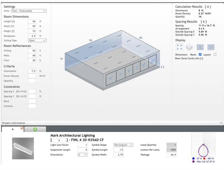
Spatial Parameters: the size of the space is a large 46’ x 59’ with about a 13.5’ ceiling height. I reduced the ceiling reflectance from the default 80% to 50% due to the darker finishes associated and planned for this spin room.
The demographic is younger and fit individuals who aren’t in need of very high illuminance to be in a safe environment lighting wise
Primarily used Mark Architectural Lighting due to its relevance for the designated program of the space
Iteration 1: Surface Mounted Lumenaire
• High performance surface mounted LED light manufactured by Mark Architectural Lighting.
• Sensor type: passive infrared. This type was chosen due to the motion heavy program in this space and the fact that it is indoors, so it wouldn’t simply be an infrared sensor.
PAGE 122 PAGE 123 Page 276 2022 Building Energy Efficiency Standards SECTION 140.6 – PRESCRIPTIVE REQUIREMENTS FOR INDOOR LIGHTING TABLE 140.6-C AREA CATEGORY METHOD - LIGHTING POWER DENSITY VALUES (WATTS/FT²) Primary Function Area Allowed Lighting Power Density for General Lighting (W/ft Additional Lighting Power Qualified Lighting Systems Additional Allowance (W/ft², unless noted otherwise) Aging Eye/Low-vision11 Corridor Area 0.70 Decorative/Display 0.30 Dining 0.80 Decorative/Display 0.30 Tunable white or dim-towarm 0.10 Lobby, Main Entry 0.85 Decorative/Display 0.30 Transition Lighting OFF at night12 0.95 Tunable white or dim-towarm 0.10 Lounge/Waiting Area 0.80 Decorative/Display 0.30 Tunable white or dim-towarm 0.10 Multipurpose Room 0.85 Decorative/Display 0.30 Tunable white or dim-towarm 0.10 Religious Worship Area 1.00 Decorative/Display 0.30 Tunable white or dim-towarm 0.10 Restroom 1.00 Decorative/Display 0.20 Stairwell 0.80 Decorative/Display 0.30 Audience Seating Area 0.50 Decorative/Display 0.25 Auditorium Area 0.70 Decorative/Display 0.45 Auto Repair Maintenance Area 0.55 Detailed Task Work 0.20 Barber, Beauty Salon, Spa Area 0.70 Detailed Task Work 0.30 Decorative/Display 0.25 Civic Meeting Place Area 0.90 Decorative/Display 0.25 Classroom, Lecture, Training, Vocational Area 0.60 White or Chalk Board W/ft Concourse and Atria Area .60 Decorative/Display 0.25 Convention, Conference, Multipurpose and Meeting Area 0.75 Decorative/Display 0.25 Copy Room 0.50 -Corridor Area .40 Decorative/Display 0.25 Dining Area Bar/Lounge and Fine Dining 0.45 Decorative/Display 0.35 Cafeteria/Fast Food 0.45 Decorative/Display 0.25 Family and Leisure 0.40 Decorative/Display 0.25 Electrical, Mechanical, Telephone Rooms 0.40 Detailed Task Work 0.20 Exercise/Fitness Center and Gymnasium Area 0.50 -Financial Transaction Area 0.70 Decorative/Display 0.25 Healthcare Facility and Hospitals Exam/Treatment Room 1.15 -Imaging Room 0.60 Decorative/Display 0.20 LOOK HERE!
03
LAB
• Quantity: 16 03
ARCHITECTURAL SYSTEMS INTEGRATION 3.3
LAB 03
ARCHITECTURAL SYSTEMS INTEGRATION 3.3
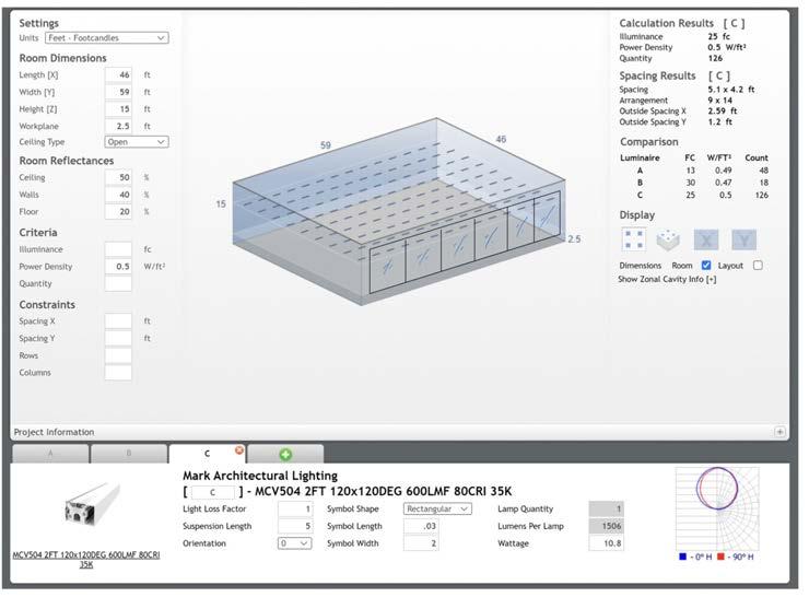
Iteration 3: Modeling with Target Lighting Power Density (LPD)
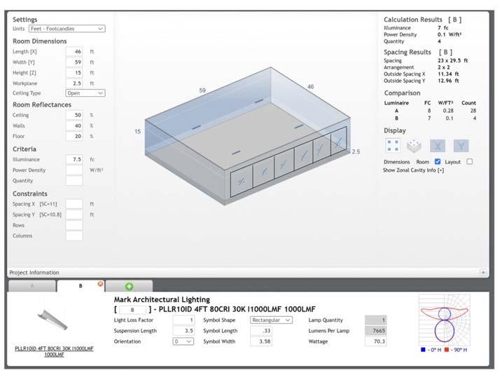
Iteration 2: Suspended Lumenaire
• Length of Suspension: 3.5’
• Quantity: 4
• Sensor Type: passive infrared. This type was chosen due to the motion heavy program in this space and the fact that it is indoors, so it wouldn’t simply be an infrared sensor.
• Con is the very low LPD that is likely due to the low quantity that is required to not exceed the desired foot candle measurement that is specified.
• This is a high performing LED lumenaire fixture
• Surface Mounted Lumenaire
• Quantity: 126
• Sensor Type: passive infrared. This type was chosen due to the motion heavy program in this space and the fact that it is indoors, so it wouldn’t simply be an infrared sensor.
• Title 24 Code for exercise space listed above: 0.5 W/SF
• This is a high performing LED lumenaire fixture
PAGE 124 PAGE 125
LAB 03
FOO ANDLE LIGH Guide FOOTC AND LE LI G HT GUID E Footcand es are the most ommon unit asu used lighting rofes nals calculate light levels busine ses and ou doo space footcandle de ne as th uminan ne squa oot surface om uni orm sourc light. he Illuminatin Engineering cie IES) recommends the following footcandle level to ensu adequa illumination and safet for cupants. el guide ine sist achi ving app pria light leve with the est ene gy-e cienc Building Area Task Average Maintained Footcandles (Horizontal) (FC) Range of Maintained Footcandles (Horizontal) (FC) Average Maintained Footcandles (Vertical) (FC) Range of Maintained Footcandles (Vertical) (FC) Comments WAREHOUSING STORAGE Bulky Items—Large Labels 10 Small Items—Small Labels 30 15 Cold Storage 20 15 Open Warehouse 20 Warehouse w/Aisles 20 15 COMMERCIAL OFFICE Open Office 40 @30” Above Finished Floor (AFF) Private Office 40 @30” AFF Conference Room 30 Mat surface efl ctan or the tab 40% nde Restroom 18 Lunch Break Room 15 20 EDUCATIONAL (SCHOOLS) Classroom 40 @30” AFF Gymnasium Pro Di College) 125 Clas (Di College) 80 Class (High School) 50 150 Class IV (Elementary) 30 100 Auditorium 7.5 10 2.5 10 Corridor 25 This guide collaborative ort of Energy Trust of Oregon and the Lighting Design Lab, Seattle, Washington. Rev.07/2013
ARCHITECTURAL SYSTEMS INTEGRATION 3.3
LAB 03
ARCHITECTURAL SYSTEMS INTEGRATION 3.3

Reflection
Integration of Iteration 1
Based on a thorough analysis, and considering lost of the variables we have gone over about electric lighting in this module of tech, the Lumenaire and system that stands out the most as the best is the one from iteration 1 with the surface mounted light. While the LPD doesn’t quite get as high as code requires, it still acheives the amount of foot candles that is necessary for the program of the space. Furthermore, the LPD required by code isn’t specified in the given manual for a “spin room” specifically, and based on how most spin rooms are, there is typically always lower lighting requirements with lights existing for emergency and mood lighting primarily. Furthermore, iteration 1 has a good balance in terms of the quantity of lights at 16, since the other two at 126 lumenaires and 4 lumenaires would either be over bearing or too greatly dispersed throughout the room to make a big impact on the space from a lighting perspective.
When inserting the minimum code requirement for an exersice space of 0.5 W/SF, it is possible for the lumenaire from the first iteration reach that number, even though that number likely doesn’t even totally apply to the specific program found in this space. Given the high performing LED nature of the light as well, this option is very good on the environment and from a budget perspective since the power load wouldn’t be as high as some non-LED options. Considering the lighting power density affects the lighting performance of the space by considering the power per square footage that the lumenaire requires, which can also have effects in the energy, comfort, and more factors of the space qualitatively as well as quantitatively. A challenge I foresee with the electric light integration in the space is being able to have enough ambient, indirect light so as not to harm the desired mood and feel of the spin room when occupied for its intended use. There has to be a balance found between code, safety, desired mood in the space, and many more factors.
PAGE 126 PAGE 127 7 8
Section Integration Drawing
LAB 03
PROJECT STATEMENT


Balboa Heights is a forward-thinking building introducing not only downtown San Diego, but the built environment as a whole to a large scale innovative, and sustainable mixed-use space. Balboa Heights seeks to answer the project-focused question of, how might we use proven sustainable design strategies to design a cohesive space that uplifts the occupants, and environment, and enhances the community while still helping students fulfill their responsibilities to current and future clients?

PAGE 128 PAGE 129
Kiah Spraker | Stacey White | Winter 2023
Project Location: San Diego, California Project Size: 60,000 SF College/University, 30,000 SF Multifamily Housing, 10,000 SF Restaurant Topography: As featured the map above, there are variety of topographical changes around our project location. Despite being close the ocean, our site lies on the top of hill, at approximately 114 feet above sea level. The site directly adjacent to sunken freeway which followed by a sharp increase slope on the other side. Nevertheless, the areas right around the project location are very walkable due to relatively small slope. Hydrology: As indicated the upper map and the one to the left, water flow the San Diego Bay combined with the effects global warming will cause an increase in sea level. In 2022 report from the National Oceanic and Atmosphereic Administration states that the ocean levels will rise by inches by 2050, which have large effect in an area like San Diego built so close to the ocean. The overall watershed that encompasses our site and most of the downtown San Diego the Pueblo Watershed. Climatic Conditions: Air Quality: The Air Quality, according to the Air Quality Index (AQI) generally considered “good” at an average 39. According to IQ Air, since 2018, the primary pollutant of PM2.5 the area has improved by 32% which shows lots of positive progress. However, San Diego still one of the worst cities in the US when comes to smog, which indicates high levels of visible air pollution. Ecosystems: Encircling the map above variety of native plant and animal species to San Diego. The increase in urbanization detrimental to all native species, and because the interconnected nature of native plants and animals in providing habitats, food, clean air, and more, essential to have open natural spaces such as Balbo Park featured in the uppr right of the map that creates safe spce for these plants and animlas to thrive. Goal Setting (Energy): LAB 01: SITE ANALYSIS NATURAL SYSTEMS Top 5 Passive Design Strategies: Sun Shading of Windows Natural Ventilation Cooling Internal Heat Gain Passive Solar Direct Gain High Mass Two-Stage Evaporative Cooling HISTORIC DATA PREDICTIVE DATA Top Passive Design Strategies: Sun Shading of Windows Natural Ventilation Cooling Internal Heat Gain Passive Solar Direct Gain High Mass High Thermal Mass Night Flushed CC BY-SA CC BY-SA CC BY-SA CC BY-SA 2.0 CC BY-SA Photo Photo Matt Photo Jennifer Digdigan Photo Craig Hunt Photo Steven Kurniawidjaja Produced by Weather.gov Based on the Target EUI found from Zero Tool, and exmaining the load profile given by Zero Code, there are tasks that can be done to reach the Target. The difference between the estimated Source EUI and the Target EUI only 6.11 kBtu/SF/yr, and the largest energy use for the project is expected to come from plug loads, followed by hot water, fans, and interior lighting. This presents solvable challenge of decreasing energy usage by optimizing applicance usage, types of lighting, cooling strategies, and more. SUN PATH DIAGRAM HOURLY TEMPERATURE CHART MONTHLY PRECIPITATION CHART WIND ROSE KIAH SPRAKER STACEY WHITE WINTER 2023 DESIGN STRATEGIES TO IMPLEMENT: Overhang for Solar Shading: Blocking harsh summer sun above apertures while making short enough such that allows the sunlight the winter when heating is wanted more. Cross Ventilation: Many Operable Doors and Windows on opposite sides of building for to travel throughout the interior spaces, allowing for natural cooling Source: 2030 Palette Source: 2030 Palette Direct Gain: Through a thermal mass, heat absorbed in the hotter daytime and released in the night when it’s cooler for passive heating. Source: 2030 Palette
Kiah Spraker | Stacey White | Winter 2023
Kiah Spraker | Stacey White | Winter 2023
EXPERIENTIAL NARRATIVE

Balboa Heights is designed to enhance the student experience, and improve their quality of life through well-designed, and affordable on-campus housing, recreational, and access to a library that goes beyond meeting their academic needs. Law students are under enormous stress, so finding proven ways to alleviate this stress through design measures can go a long way. The student body served is very diverse in many facets, so making sure we are paying attention to many different groups and not prioritizing one in terms of temperatures, accessibility, and more is essential. Furthermore, considering that a large amount of the building program is dedicated to housing, we must consider the diverse living requirements of the students, because as graduate students, there is the potential of many families not only with spouses but with kids as well that would need to be designed for as well. With a vertical park being integrated into all functions and spaces of the building, I want the students to feel a sense of peace and refreshment as they have a connection to nature built directly into their living and working environment. As they move through the building, want them to be able to focus on themselves and their important topics, without hearing extraneous noise from the highway or potentially loud spaces within other parts of the building. Overall, I want the students to feel a sense of ownership of the space and help them feel at home, so they can work on bettering themselves and their community through study, recreation, nutrition, and personal space. The other group of people meant to experience part of this building is the general community, and students that might not live in the housing on the upper floors. With the bottom floor of the building being dedicated to a more public library and cafe space, it is meant to enhance the civic life of downtown San Diego, and encourage important connections between students and the rest of the local community. This bottom floor is expected to be more lively and exciting as people from many generations, backgrounds, and cultures are mixed in a space welcoming to all.
PROJECT GOALS
SAFETY AND WELLBEING: HOW MIGHT WE DESIGN A CAMPUS WITH THE SYSTEMS AND SPACES IN PLACE THAT POSITIVELY CONTRIBUTE TO THE COMMUNITY EXPERIENCE?
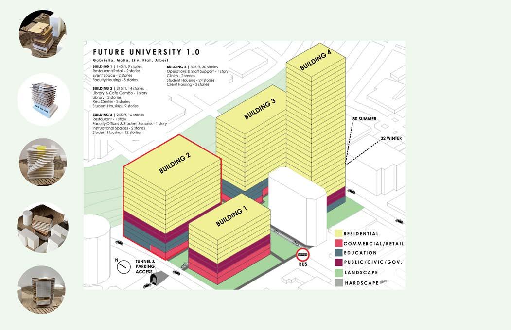
SUSTAINABILITY HOW MIGHT WE RESPONSIBLY DESIGN HEALTHY SPACES THAT UPLIFT OCCUPANTS AND HELP REDUCE THE HARMFUL EFFECTS OF CLIMATE CHANGE?
ACADEMICS: HOW MIGHT WE PROVIDE DIVERSE SPACES THAT PROMOTE ACADEMIC SUCCESS WHILE ALSO ACKNOWLEDGING THE DEMAND OF LAW SCHOOL?
OBLIGATIONS: HOW MIGHT WE DESIGN TO THE NEEDS AND WANTS OF THE LAW STUDENTS AND ALLOW THEM TO FULFILL THEIR OWN RESPONSIBILITIES?
COMMUNITY: HOW MIGHT WE DESIGN A CAMPUS IN WHICH STUDENTS ARE ABLE TO INTERACT WITH THE COMMUNITY THEY WILL BE WORKING WITH?
PAGE 130 PAGE 131
Central Plant for Air Based Systems
Kiah
Lily Albert
Gabriella
Malia
Central Plant for Air Based Systems
Kiah Spraker | Stacey White | Winter 2023
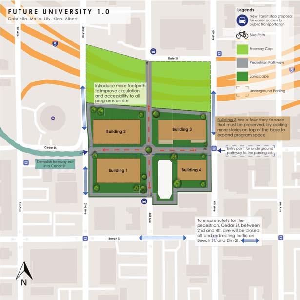
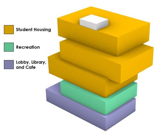
PAGE 132 PAGE 133
SITE PLAN
Kiah Spraker | Stacey White | Winter 2023
Space Needs No.PeopleASF per Total ASFNotes Library User Spaces 41,350 Quiet Study 1 6001500015,000 Individual Study 1 3001050010,500 Open (Lively) Study 1 6001500015,000 Computer Lab 1 60700700 Librarian Office 12 150150 0 Public Space 28,260 Lobby 1 5010001,000 Service Desks 32 120360 Café 11 180180 Seating/ordering 1 507501,000 Kitchen 10 400400 Print and Copy 10 400400 Gym Locker Room 2 15020004,000 Basketball/VB 1 2050003,000 Pickleball/tennis 1 1630003,000 Climbing Wall 1 1010001,000 Sauna 44 30120 Weight Room/mach 1 100800010,000 Yoga Studio 2 205001,000 Multi-purpose 1 5020002,000 Spin Room 2 20400800 Storage 12 400400 Housing 147,800 Studio 150 40060,000 1 Bedroom 100 50050,000 2 Bedroom 50 70035,000 Community Rooms 4 7002,800 Subtotal (ASF) 217,410 Total (GSF) 334,477 11th Floor 12th Floor 13th Floor
Kiah Spraker | Stacey White | Winter 2023

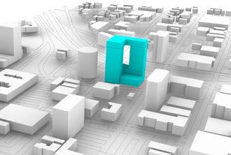
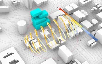


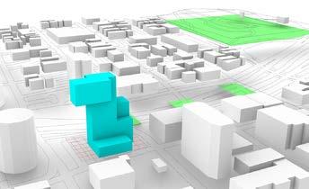
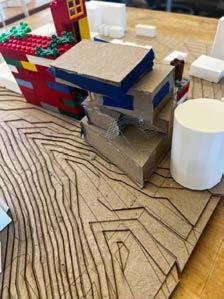
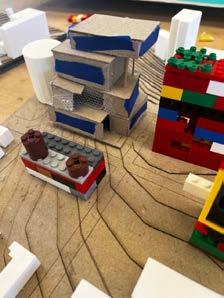
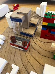
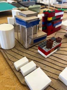
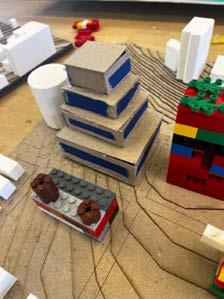
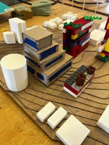
PAGE 134 PAGE 135
Building Context Focus Unusual Form Focus Daylighting Focus Prevailing Wind Direction Focus Welcming Entrance Focus Providing Good Views Focus
Kiah Spraker | Stacey White | Winter 2023
Kiah Spraker | Stacey White | Winter 2023
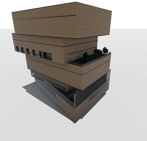
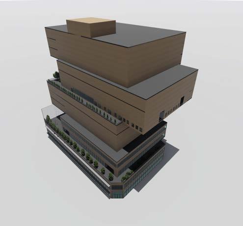
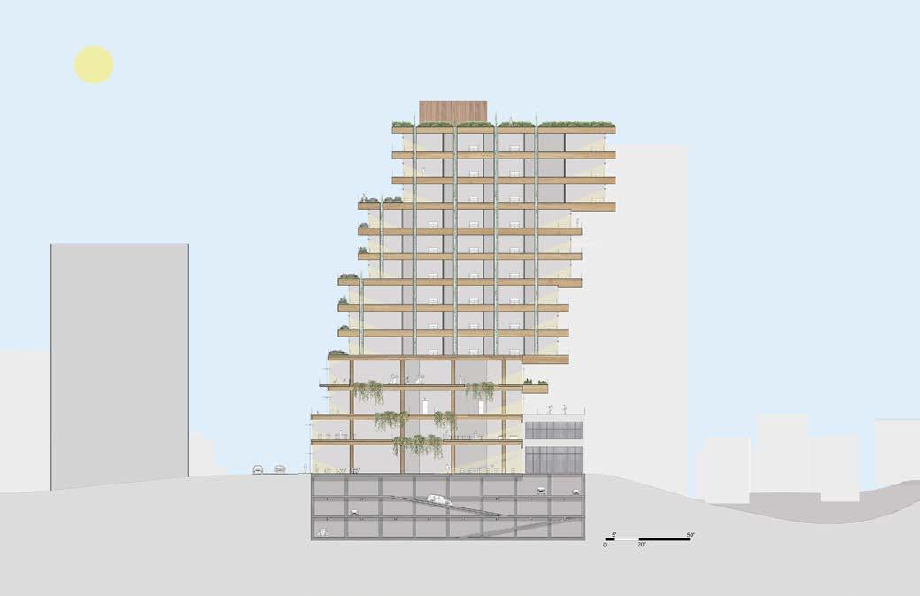
PAGE 136 PAGE 137
BUILDING MASSING
Kiah Spraker | Stacey White | Winter 2023
N
1/32” = 1’-0”
BUILDING SECTION
PAGE 138 PAGE 139
Residential Lobby Public Lobby 2005 SF FAN ROOM 0' 5' 20' 40' Scale Date 3/64" = 1'-0" Ground Floor Plan Balboa Heights Cal Western Law School Campus, San Diego, CA 2/14/2023 3/64" = 1'-0" 1 1st Floor
Kiah Spraker | Stacey White | Winter 2023
0' 5' 20' 40' Scale Date 3/64" = 1'-0" 3RD FLOOR PLAN - REC Balboa Heights Cal Western Law School Campus San Diego, CA 2/14/2023 3/64" = 1'-0" 1 3rd Floor
Kiah Spraker | Stacey White | Winter 2023
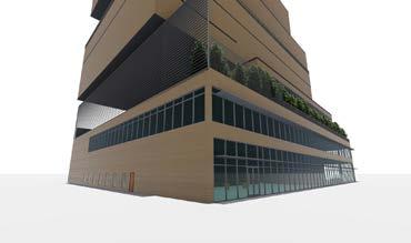
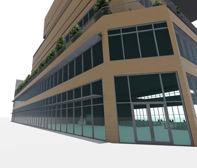
PAGE 140 PAGE 141
0' 5' 20' 40' Scale Date 3/64" = 1'-0"
Balboa
Cal Western
School
San
CA 2/14/2023 3/64" = 1'-0" 1 8th Floor
Kiah Spraker | Stacey White | Winter 2023
8TH FLOOR PLAN - HOUSING
Heights
Law
Campus
Diego,
Kiah Spraker | Stacey White | Winter 2023 EXTERIOR
VIGNETTE
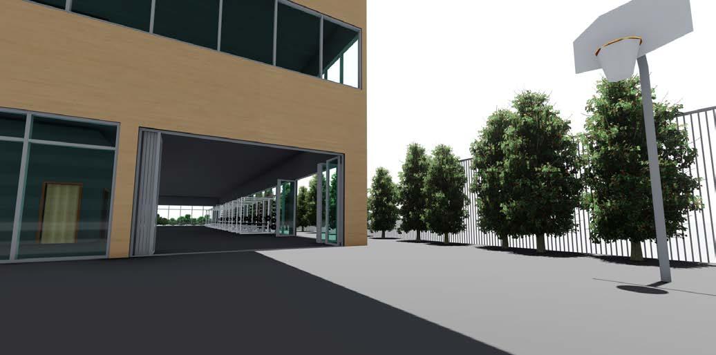


PAGE 142 PAGE 143
Kiah Spraker | Stacey White | Winter 2023
EXTERIOR VIGNETTE Kiah Spraker | Stacey White | Winter 2023
INTERIOR VIGNETTE
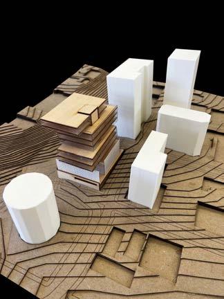
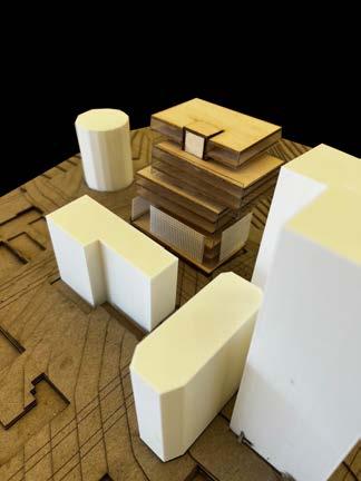
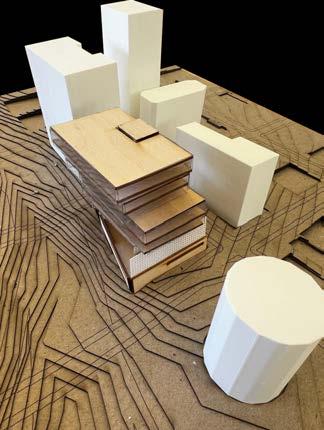
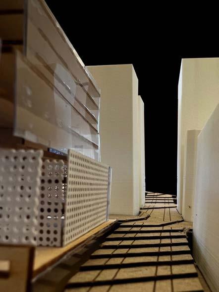
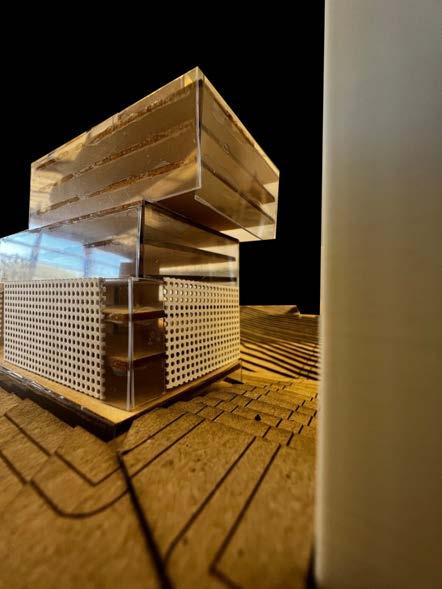
PAGE 144 PAGE 145
Kiah Spraker | Stacey White | Winter 2023
Kiah Spraker | Stacey White | Winter 2023