A century in business has taught us that you can never go wrong when you focus on the needs of the customer and the importance of getting every project right the first time. We know that committing to innovation and quality are the best paths to reduced lubricant consumption, gas stream contamination and downtime. Our focus on reliable, dependable service is invaluable to earning trust and building long-term relationships. It’s not a gimmick. It’s just the way we do business and why we’re the first name in compressor lubrication.
EDITORIAL
Editor
Jack Burke
jack.burke@khl.com
Vice President of Content, Power
Becky Schultz
becky.schultz@khl.com
PRODUCTION
Client Success & Delivery Manager
Charlotte Kemp
charlotte.kemp@khl.com
Group Design Manager Jeff Gilbert
Group Designer Jade Hudson
Events Manager Steven Webb
steven.webb@khl.com
Events Design Manager Gary Brinklow
Creative Designer Kate Brown
CIRCULATION
Subscriptions circulation@khl.com
Data Manager Anna Philo
anna.philo@khl.com
Data Executive Vicki Rummery
vicki.rummery@khl.com
SALES
Brand Manager
PLUS mainland Europe
Gabriele Dinsel
+49 711 34 06 73 50 | gabriele.dinsel@khl.com
China
Cathy Yao
+86 (0)10 6553 6676 | cathy.yao@khl.com
Italy
Giuseppe Di Leva
+44 (0) 7593 586562 | giuseppe.dileva@khl.com
Japan
Michihiro Kawahara
+81 (0)3 32123671 | kawahara@rayden.jp
Scandinavia/UK/Benelux
Greg Roberts
+44 (0) 7950 032224 | greg.roberts@khl.com USA
Kristin Pride
+1 720 298 8546 | kristin.pride@khl.com
Vice President Sales, Power Division
Tony Radke
480 478 6302
tony.radke@khl.com
Global Vice President Sales
Alister Williams
+1 312 860 6775
alister.williams@khl.com
Chief Executive Officer
James King
Chief Financial Officer
Paul Baker
Chief Operating Officer
Trevor Pease
HAL is hungry for more power
For some of us over a certain age, our first introduction to “Artificial Intelligence” was HAL (full name: Heuristically Programmed Algorithmic Computer 9000), the seemingly omniscient onboard computer in “2001: A Space Odyssey.”
In the movie, HAL speaks calmly, almost softly and does the bidding of the two crew members right up until he (it?) tries to kill them both. Sorry for the spoiler.
My recent experiences with AI have been much less dramatic. Or omniscient, quite frankly.
I recently asked AI to condense a company’s earnings report and it quickly spit out a nice, concise overview. Problem was, it made up the name of the company’s CEO, which was in the original material. Honestly, I don’t need help making mistakes.
On the other hand, I recently took part in a Midstream class that had us work as teams to develop a gas processing plant, given certain parameters such as was the gas wet or dry, the pipeline pressure, the sulfur content. As a test, one team plugged the data into an AI chatbot, and it spit out a detailed analysis that raised eyebrows throughout the room.
One field operations guy joked (sort of) that maybe companies won’t need engineers anymore.
So what’s AI got to do with our industry? Power.
The International Energy Agency (IEA) recently released a report on the AI-energy connection. Here are some highlights:
■ Data centers accounted for about 1.5% of global electricity use last year. It’s projected to more than double by 2030 to surpass Japan’s current overall demand.
■ In IEA’s base case, renewables make the largest contribution to meeting data center demand growth through 2035, followed by natural gas, though it varies a lot by region.
A key finding: “A typical AI-focused data center consumes as much electricity as 100,000 households, but the largest ones under construction today will consume 20 times as much.”
That’s a lot of power. And a lot of power requires a lot of natural gas. Fact is, if those projections come true, pretty much every source of energy will be needed. But no energy source is as readily available, as easily dispatchable and as economical as natural gas.
Perhaps HAL can come up with another power source, but I’ll wager his (its?) answer would be “Sorry... I’m afraid I can’t do that.”
Jack
Burke Editor
| jack.burke@khl.com
20 Regional Report: Opportunities, challenges in the Marcellus
26 Tools for condition-based monitoring
32 Technology updates from GCA Expo
DEPARTMENTS
3 Editor’s Comment: HAL is hungry
30 | NUMBER 5
COMPRESSORTECH2 ISSN 1085-2468, is published monthly with combined issues of January/ February and August/September by KHL Group Americas LLC, 14269 N 87th, Suite 205, Scottsdale, Arizona, 85260, USA. Periodicals postage is paid at Scottsdale, AZ, and additional mailing offices (if applicable).
POSTMASTER
Send address changes to KHL Group Americas LLC, 14269 N 87th, Suite 205, Scottsdale, Arizona, 85260, USA.
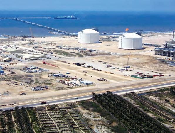
54 Report: The state of LNG in the Mediterranean
TAKE 5
24 Sarah Miller, leader of GPA Midstream Association and GPSA
LNG, HYDROGEN
Highlights of CT2 webinar
Hydrogen roundtable
6 Industry News: Woodside moves ahead with Louisiana LNG
8 Gas Lines: Eagle Ford set to spike 10 Company News: U.S. Energy expands carbon capture acreage
57 Cornerstones of Compression: Part III of Compressor Corrolaries: Refrigeration compressors
Woodside moves forward with Louisiana LNG
Woodside has signed a long-term agreement with bp to source natural gas for its proposed Louisiana LNG project, marking a key milestone as the Australian energy major continues to advance the U.S. Gulf Coast export terminal.
The agreement commits bp to deliver up to 640 billion cubic feet of gas to the project’s gas marketing subsidiary, Louisiana LNG Gas Management LLC (GasCo), starting in 2029. Gas will be ultimately delivered to Line 200, one of several pipelines serving the terminal’s strategically connected site.
“This is an important step for the project,” said Woodside CEO Meg O’Neill. “Securing this gas supply agreement is a milestone...”
The Louisiana LNG terminal is among Woodside’s most significant growth initiatives. The project is designed with access to a wide range of U.S. gas supply sources, including the Haynesville and Permian basins, via interconnects with major pipeline systems in Louisiana. The company has previously stated
TotalEnergies Brings Ballymore online
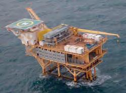
TotalEnergies has announced first production from the deepwater Ballymore field in the U.S. Gulf of Mexico, adding new natural gas and oil volumes to its growing offshore portfolio. The company holds a 40% stake in the project, operated by Chevron (60%).
Located about 120 km off the Louisiana coast, Ballymore was launched in May 2022 and is now producing through a subsea tieback to Chevron’s Blind Faith floating production unit. The project has a gross daily capacity of 75,000 barrels of oil and 50 million cubic feet of gas, contributing valuable new volumes to the region’s offshore natural gas production.
FOX INNOVATION & TECHNOLOGIES has acquired Italian turbomachinery specialist SIRIO SOLUTIONS ENGINEERING (SSE), strengthening its position in the global high-speed rotating equipment market and adding sophisticated control systems capabilities to its expanding platform.
The acquisition is Fox’s third since its inception and aligns with the company’s strategy of building a full-service offering for industrial process and energy infrastructure applications. SSE, based in Prato, Italy, brings nearly 40 years of
experience in engineering control systems for turbomachinery and providing field services to major OEMs and end-users.
SSE’s extensive field services footprint in Europe, the Middle East, North Africa, South America and Eurasia will complement Fox’s existing service base in the United States. SSE also maintains international facilities, including in Iraq and Brazil.
THE U.S. GOVERNMENT has identified 16 federal sites where data centers and
Australian oil and gas major Woodside Energy said it had signed a supply deal with bp, under which the British energy giant would supply natural gas to its Louisiana liquefied natural gas (LNG) project.
that Louisiana LNG will offer up to 13 million tonnes per annum of export capacity in its initial phase, with the potential for future expansion.
“By drawing upon bp’s experience with MiQ certificates, we can access verifiably low methane intensity molecules,” ONeill said. “This supports Woodside’s goals as a member in the UN Environment Programme’s OGMP 2.0 initiative.” CT2
energy generation projects could be co-located, aiming to accelerate artificial intelligence (AI) infrastructure and boost domestic energy production.
The Department of Energy (DOE) announced the initiative on April 3, with plans to form public-private partnerships and begin operations by the end of 2027, according to media reports.
As data centers drive soaring electricity demand — forecast to more than double in the U.S. from 176 TWh in 2023 to up to 580 TWh in 2028 — the government is
IMAGES: WOODSIDE
Concepts NREC, ADS CFD in partnership
Concepts NREC and ADS CFD have partnered to integrate high-speed GPU-accelerated CFD technology directly into the Agile Engineering Design System (AEDS). This collaboration allows designers to perform CFD simulations 15 to 120 times faster than conventional CPU-based solvers, while significantly lowering hardware costs, the companies said. At the core of the partnership is the integration of ADS Code LEO, a wellestablished CFD solver optimized for GPU acceleration, and ADS Code WAND, an automated mesh generator for multistage turbomachinery. The companies said these tools are now seamlessly embedded into the AEDS software suite — a specialized platform for turbomachinery CAE and CAM applications — enabling users to run high-fidelity CFD calculations with a single click.
rethinking its energy priorities. While renewable energy continues to grow, the Trump administration has signaled a commitment to natural gas and nuclear power.
According to the U.S. Energy Information Administration (EIA), natural gas accounted for 42% of the U.S. generation mix in 2024, but is forecast to dip slightly to 40% in 2026 as renewables rise. Despite that, the DOE emphasized natural gas remains key to national energy security.
CO2 storage project advances
Öresundskraft Kraft & Värme AB and INEOS, on behalf of Project Greensand, have signed an agreement to explore the storage of up to 210,000 tonnes of carbon dioxide (CO2) annually from Sweden in Denmark, the companies announced. The captured CO2 would be permanently stored at the Greensand storage facility in the Danish sector of the North Sea, with the first volumes expected to be stored starting in 2028.
The partnership represents a major step forward for carbon capture and storage (CCS) efforts in the Greater Copenhagen area and highlights the growing importance of international cooperation in tackling climate change.
INEOS, together with its Project Greensand partners Harbour Energy and Nordsøfonden, is developing one of Europe’s most advanced CO2 storage sites. Greensand aims to receive CO2 from several European countries for safe, permanent
INEOS, together with its Project Greensand partners Harbour Energy and Nordsøfonden, is developing one of Europe’s most advanced CO2 storage sites. Greensand aims to receive
injection into offshore geological formations.
The announcement follows INEOS and its partners’ Final Investment Decision (FID) in 2024 to proceed with full-scale CO2 storage operations in Denmark’s Nini Field, part of the Greensand project. Full operations are slated to begin by early 2026, positioning Greensand as the European Union’s first operational offshore CO2 storage facility. The project is expected to drive more than 1 billion Danish kroner in investments to expand storage capacity. CT2
Neuman & Esser earns hydrogen storage project order in Germany
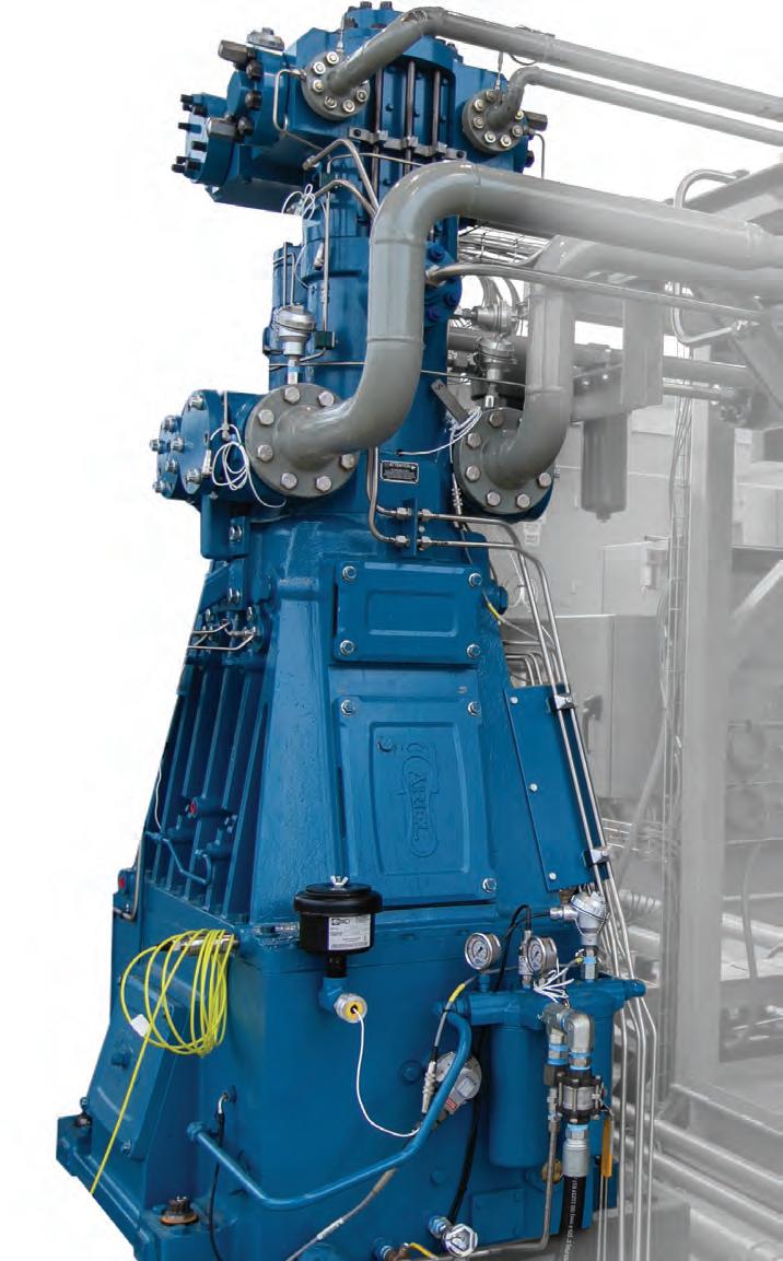
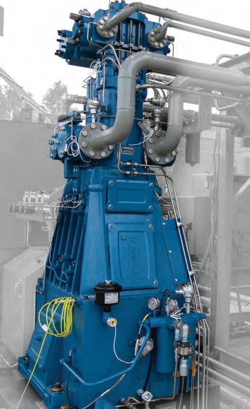
Neuman & Esser will supply two four-crank, horizontal piston compressors to German energy company EWE for a major hydrogen storage project along the country’s North Sea coast.
The compressors, size 320, will play a central role in EWE’s “Clean Hydrogen Coastline” project, which aims to convert an existing underground natural gas cavern in Huntorf, Lower Saxony, for large-scale hydrogen storage. EWE plans to begin
storing hydrogen at the site by 2027.
The Huntorf project is part of a fourpart initiative that integrates hydrogen production, storage, transportation and use in line with European energy transition goals. EWE received funding approval in 2024 through the Important Project of Common European Interest (IPCEI) program and is currently in the detailed planning phase.
EWE previously demonstrated the feasibility of hydrogen storage in pilot salt caverns near Berlin and now plans to scale the technology for commercial use elsewhere. CT2
Neuman & Esser will supply two horizontal piston compressors for a hydrogen storage project in Northern Germany. IMAGE: NEUMAN & ESSER
GAS LINES EAGLE FORD GAS PRODUCTION
Eagle Ford gas production set to climb
Natural gas production in the Eagle Ford region of southwest Texas is projected to continue its upward trajectory over the next two years, according to the U.S. Energy Information Administration (EIA). In its April Short-Term Energy Outlook, the EIA forecasts that annual natural gas output in the region will rise from 6.8 billion cubic feet per day (Bcf/d) in 2024 to 7.0 Bcf/d in 2026.
The growth in natural gas production comes amid rising natural gas prices and increasing global demand for liquefied natural gas (LNG) exports. In contrast, oil production in the Eagle Ford has remained relatively flat, averaging around 1.1 million barrels per day (b/d) since 2020, and the EIA expects it will stay near that level through 2026.
The production trends are being driven by rising gas-oil ratios in the region’s reservoirs. As oil and gas wells mature and pressure within the reservoirs declines, more natural gas is produced relative to oil.
The Eagle Ford region encompasses
AVERAGE ANNUAL EAGLE FORD NATURAL GAS AND CRUDE OIL PRODUCTION (2010-2026)
several plays, including the prolific Eagle Ford and Austin Chalk formations. Development in the Austin Chalk began nearly a century ago but has experienced a resurgence since 2014. Since then, oil production from the play has nearly quadrupled, while natural gas output has surged by nearly 675%. Currently, the Eagle Ford play accounts for 73%
(5.5 Bcf/d) of the region’s natural gas production and 86% (1.0 million b/d) of its oil production. Since 2020, natural gas production from the play has grown by 10% (0.5 Bcf/d), while oil output has dipped by 4% (46,000 b/d).
The Austin Chalk play is the fastestgrowing play in the region, with gas production nearly tripling since 2020. CT2
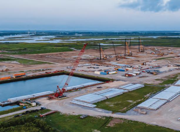
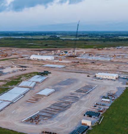
Kodiak expands Permian presence
Kodiak Gas Services, a leading provider of contract gas compression and related services, started construction on two new facilities in the Permian Basin. The projects, located in Midland and Pecos, Texas, are part of Kodiak’s ongoing efforts to enhance operational capacity and workforce development.
The Permian Basin continues to be a critical region for natural gas production, and Kodiak’s latest infrastructure investments are designed to support both current demand and anticipated future growth.
The Midland campus will span nearly 22 acres, with over 140,000 square feet of shop, training, and office space. It will also serve as the new home of Bears Academy, Kodiak’s employee training and development center. The facility will feature indoor training labs with virtual reality tools, classrooms, and onsite accommodations for trainees.
WILLIAMS announced that Larry Larsen has been appointed executive vice president and chief operating officer, effective May 3, 2025. He will oversee all aspects of the company’s transmission, storage, and gathering and processing operations.
Larsen succeeds Micheal Dunn, who announced his planned retirement last month. Larsen currently serves as Williams’ senior vice president of gathering and processing.
“Larry’s deep understanding of Williams’ operations and natural gas focused
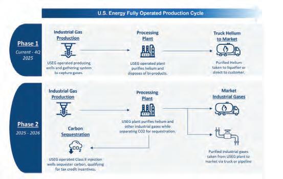
U.S. Energy expands
U.S. Energy Corp. has expanded its carbon capture and industrial gas development platform with the acquisition of 2,300 net acres and a permitted Class II injection well in Montana’s Kevin Dome, a geologic structure known for its helium-rich and CO2-dominated gas systems.
The $200,000 acquisition from a privately held company strengthens U.S. Energy’s control of highly contiguous acreage in the
Kinder Morgan betting on natural gas’s future
Kinder Morgan reported first-quarter net income of $717 million, slightly down from $746 million a year ago, while adjusted net income edged up 1% to $766 million. Adjusted EBITDA also rose 1% to $2.16 billion, driven by solid performance in its Natural Gas Pipelines, CO₂, and Terminals business segments. Free cash flow for the quarter reached $400 million after capital expenditures.
“Despite concerns about an economic downturn, our long-term, fee-based business model continues to provide stability,” said Executive Chairman Richard D. Kinder. “We believe Kinder Morgan
strategy make him the ideal candidate for our next COO, ensuring a seamless transition and continuity in leadership,” said Alan Armstrong, president and CEO of Williams. “He brings a depth of experience and knowledge that will allow us to continue optimizing our operations to enhance Williams’ competitive advantage and advance the execution of our long-term growth strategy.”
Larsen joined Williams in 1999, beginning his career within the Northwest Pipeline franchise. He later served as vice president
region and adds critical infrastructure to support its carbon capture, utilization, and storage (CCUS) strategy. The Class II well, permitted under the U.S. Environmental Protection Agency’s Underground Injection Control (UIC) Program, will be used to sequester CO2 captured from U.S. Energy’s planned industrial gas processing facility, expected to begin operations in the near future.
“This acquisition marks a meaningful
remains a reliable port in the storm, as it has in past cycles.”
Kinder Morgan is capitalizing on record U.S. natural gas production and rising demand, especially from liquefied natural gas (LNG) export facilities and power plants. CEO Kim Dang highlighted the company’s
of Central Services, leading supply chain, commodity services, marketing, measurement, and pipeline control functions.
In 2018, he became vice presidentgeneral manager for the Rocky Mountain Midstream franchise and was responsible for commercial activities and operations in the region.
In 2020, Larsen was named vice president of strategic development, leading corporate strategy, market intelligence, and corporate development
A Kinder Morgan LNG facility. The natural gas pipeline giant remains bullish on natural gas demand. IMAGE: KINDER MORGAN
Kodiak Gas Services breaks ground on stateof-the-art facilities in Midland and Pecos.
carbon capture acreage
milestone forward in our efforts to integrate carbon sequestration into our industrial gas platform,” said Ryan Smith, CEO of U.S. Energy. “The addition of permitted injection infrastructure and strategic acreage strengthens our position across the Kevin Dome and accelerates our ability to deliver clean, domestically sourced helium while sequestering CO₂ at scale.”
The company plans to submit a Monitoring, Reporting, and Verification (MRV)
plan to the EPA for the well in the second quarter of 2025, ensuring its longterm compliance and operational integrity as part of U.S. Energy’s broader CCUS initiative.
This acquisition aligns with U.S. Energy’s strategy to build a scalable, low-emission industrial gas operation while positioning itself as a leading U.S.-based supplier of clean helium and other critical gases. The company continues to target assets and infrastructure that support growing footprint in the Bakken region with the $640 million acquisition of Outrigger Energy II’s gathering and processing system — a move backed by long-term contracts with major customers.
“Domestic natural gas production hit record highs in the first quarter, and demand continues to surge,” Dang said. LNG feedgas demand alone was up 15% year-over-year, while residential and commercial natural gas use rose 10%.
Looking ahead, Kinder Morgan anticipates U.S. natural gas demand could increase by 20 to 28 billion cubic feet per day (Bcf/d) by 2030. The company currently transports around 7 Bcf/d to LNG facilities and expects that to rise to 11 Bcf/d by the end of 2027, with more projects in development.
efforts. He has served as senior vice president of gathering and processing since 2022, managing Williams’ onshore gathering and processing, NGL transmission, storage, and fractionation businesses.
Larsen holds a Bachelor of Science degree in mechanical engineering from the University of Utah.
Williams operates a 33,000-mile pipeline network and transports about one-third of the natural gas consumed in the United States.
responsible growth and contribute to lowering the carbon footprint of industrial gas operations. CT2
Lhyfe secures €149 million grant for green H2 plant in France
Green hydrogen producer Lhyfe is moving forward with one of France’s most ambitious renewable energy projects, securing a €149 million grant to build a large-scale hydrogen production facility in Le Havre’s industrial port zone. The project, dubbed Green Horizon, is expected to reach a production capacity of up to 34 tonnes of green hydrogen per day when completed by 2029.
The facility will be located on a 2.8-hectare site in Gonfreville-l’Orcher, near the Grand Canal du Havre — one of Europe’s largest industrial ports. Once operational, the plant will supply lowcarbon hydrogen to regional industries and mobility sectors, including neighboring companies like Yara, whose decarbonization plans rely heavily on access to renewable hydrogen. CT2
CAPTUREPOINT and CAPTUREPOINT SOLUTIONS, together one of North America’s leading private carbon management companies, announced the appointment of Greg Harper as chief executive officer and member of the Board of Directors, effective immediately.
Harper, a veteran of the U.S. energy sector with more than 35 years of leadership experience, steps into the role as the company accelerates its growth in Carbon Capture, Utilization, and
Sequestration (CCUS). He succeeds Tracy Evans, CapturePoint’s founder and former CEO, who recently retired.
CapturePoint operates over 1 million tons of CO2 injection annually through Enhanced Oil Recovery (CO2-EOR) projects and manages more than 230 miles of dedicated CO2 pipelines across Oklahoma and Texas. The company is actively developing several large-scale carbon storage hubs, including the CENLA Hub in Louisiana.
40-year-old rules eyed
PHMSA seeks industry input on LNG safety rule overhaul. By
Brian Ford
It’s been more than 40 years since the first U.S. liquefied natural gas (LNG) safety rules were enacted, and the U.S. Department of Transportation’s Pipeline and Hazardous Materials Safety Administration (PHMSA) says it’s high time for a major update.
As part of President Donald Trump’s “energy dominance” agenda, U.S. Transportation Secretary Sean Duffy announced that PHMSA is seeking comment on a proposed rulemaking to “revamp decades-old regulations and slash red tape to increase LNG exports, generate goodpaying jobs, and allow the U.S. to safely send more of its natural resources around the world.”
Regs cover gamut
PHMSA’s regulations—which haven’t been substantially revised in more than two decades—cover the siting, design, installation, construction, inspection, testing, operation and maintenance of LNG facilities, according to the agency.
“In the years since, the U.S. LNG industry has become truly global in scale and geopolitical importance; the sophistication of technology and operating practices within LNG facilities regulated by PHMSA have similarly evolved at a breakneck pace,” the agency said. It added that Congress, the Government Accountability Office
and industry stakeholders have repeatedly called for regulatory updates.
PHMSA’s last significant amendments to its regulations governing LNG facilities date to 2004. At that time, most LNG facilities regulated by the agency “were relatively small facilities focused on the U.S. domestic market: LNG import facilities and ‘peak-shaving’ facilities”—those that help power natural gas-fired plants during peak demand—supporting local gas distribution companies, PHMSA said.
Long-time scrutiny
The agency has been working to update the rules since the final years of the Obama administration but “hasn’t even published a draft,” according to E&E News by Politico.
Meanwhile, fueled by the domestic shale gas boom, the U.S. has become the largest exporter of LNG, supplying roughly 22% of the global LNG market. A recent study estimates the U.S. LNG industry will contribute about $1.3 trillion to U.S. gross domestic product over the next 16 years, according to PHMSA.
The industry has “compiled and memorialized the lessons learned and best practices in designing, constructing and operating each of these types of LNG facilities over the last two decades in consensus industry standards,” the agency said.
Seeking ideas
In its advance notice of proposed rulemaking (ANPRM), PHMSA is seeking stakeholder input on topics such as:
■ Are there aspects of the regulations that are particularly burdensome on the ability of industry to operate LNG facilities that PHMSA should consider amending or rescinding?
■ Are there areas where PHMSA could add regulatory text that would reduce costs for operators without compromising safety?
■ Which aspects of the current regulations
PHMSA’S last significant amendments to the regulations governing LNG facilities came in 2004, but the industry has grown wildly since then.
do operators find outdated or unnecessary because industry practices or existing guidelines provide better standards in terms of cost savings and safety?
■ How can PHMSA best design a rulemaking to update its regulations for LNG facilities in a way that is deregulatory and results in cost savings for the industry?
Comments on the ANPRM are due by July 7.
Some cautious
While the LNG industry may welcome the proposed rulemaking as a sign of regulatory relief, at least one organization is voicing caution.
“While it’s wonderful to see PHMSA finally addressing the long-outdated LNG safety regulations, it’s hard to reconcile this effort with PHMSA’s references to this being deregulatory,” Pipeline Safety Trust Executive Director Bill Caram said in a statement. He noted that stakeholders were being asked to suggest ways the agency could deregulate LNG facilities in a manner that leads to industry cost savings.
Caram urged PHMSA “to center this regulatory update on strengthening safety protections for communities near LNG facilities, rather than primarily focusing on operational efficiencies.” CT2
BRIAN FORD is editor in chief for Industrial Info Resources, which provides up-to-date project information on a wide range of industries across the globe. He has worked as a reporter and editor for newspapers and other publications since 1979.
PISTON
Intermediate
Deepest/oldest Prospective
PERMIAN (Delaware, Midland)
Survey work begins for Trident project
Preliminary survey work is progressing on Kinder Morgan’s $1.6 billion Trident Intrastate Pipeline project from Katy, Texas, to the LNG and industrial corridor near Port Arthur, Texas. Kinder expects the project to be in service early 2027.
USEDC buys 20,000 acres
U.S. Energy Development (USEDC) has significantly expanded its presence in the Permian Basin by acquiring 20,000 net acres in Reeves and Ward Counties, Texas, for $390 million.
The company plans to invest up to $1 billion in U.S. oil and gas properties in 2025, focusing primarily on the Permian Basin.
James Willis highlights the latest news from the major North American shale plays
MARCELLUS/UTICA
EQT buying Olympus Energy
EQT Corporation announced a deal to buy Olympus Energy (formerly Huntley & Huntley Energy Exploration) for $1.8 billion in stock and cash. The Olympus assets comprise what EQT describes as a vertically integrated contiguous 90,000 net acre position, offsetting EQT’s existing core acreage in
ROCKIES (Powder River Basin, Denver-Julesburg Basin, Niobrara)
Williams drilling in the Lewis Shale
Williams is expanding its upstream operations in Wyoming’s Green River Basin, particularly targeting the oil-rich Lewis Shale, after acquiring full ownership of the Wamsutter Field joint venture from Crowheart Energy for $307 million.
southwestern Pennsylvania with net production of approximately 500 MMcf/d. The transaction is expected to close early in the third quarter of 2025.
BAKKEN/WILLISTON
Hess drills first 4-mile wells
180 miles of greenfield pipe in Ohio Utica
Boardwalk Pipeline Partners plans to build the Borealis Natural Gas Pipeline Expansion Project, a 180-mile greenfield pipeline that will span nearly the entire length of Southern Ohio. The pipeline will allow 2 Bcf/d of Utica Shale gas to flow into the Texas Gas Transmission pipeline network, reaching new markets from the Midwest to the Southwest. This is the first major greenfield pipeline project in the northeast proposed since the 303-mile Mountain Valley Pipeline was completed last year.
Evolution sets Marcellus e-fracking record
Evolution Well Services,
In early February, Hess launched North Dakota’s first 4-mile lateral wells in its Beaver Lodge field, marking a major technical and strategic milestone. These extended-reach wells lower breakeven costs, boost estimated ultimate recovery, and expand development potential beyond core acreage by reducing economic thresholds. Long wells also shrink Hess’s environmental footprint by minimizing surface disturbance, trucking, and labor needs. The achievement was realized in just a year from planning to production, aided by experience from prior 2- and 3-mile wells and collaboration with rig operator Nabors Industries. Additionally, Hess drilled a 2-mile observation lateral overlapping the last segments of the 4-mile wells.
HAYNESVILLE
BKV, Comstock partner on CCUS
BKV Corp. and Comstock Resources announced an exclusive, nonbinding agreement for BKV to develop carbon capture, utilization, and sequestration (CCUS) projects at two of Comstock’s natural gas processing facilities in its Western Haynesville operating area. As part of the agreement, the companies plan to develop CCUS injection wells to permanently sequester carbon dioxide waste produced at Comstock’s Bethel and Marquez natural gas processing and production facilities in Texas, as well as other locations.
headquartered in Houston with a regional office in Pittsburgh, specializes in electric fracking (“e-fracking”) — using natural gas from the well pad instead of diesel fuel to power turbines that create electricity to drive fracking pumps. In a landmark achievement, EQT Corporation, the country’s second-largest natural gas producer, and
Evolution Well Services, a leader in e-fracking, have set a new continuous pumping record in the Marcellus/Utica. The record set includes pumping for 47.35 hours straight at the prescribed job design with zero non-productive time. This new record included moving 262,000 barrels of water and 11.44 million pounds of sand in
the challenging terrain of West Virginia—all of it without taking a break from pumping.
WV law allows CO2 stored under state-owned parks West Virginia removed a ban on leasing “pore spaces” under state-owned parks. The bill explicitly prohibits any surface disturbance on state park land for drilling or injection. All lease revenues generated must be used exclusively for improvements and maintenance at the location where the leased pore space is situated. The bill (now law) also stipulates that the center of any well pad under lease for state park pore space must be at least 200 feet from the park boundary. The law goes into effect on July 8. CT2
EAGLE FORD (Austin Chalk, Tuscaloosa Marine Shale)
Undiscovered
O&G in Maverick Basin
The U.S. Geological Survey (USGS) released an assessment of the potential for undiscovered oil and gas in formations of the Maverick Basin, estimating that there are technically recoverable resources of 366 million barrels of oil and 11 Tcf of gas. The assessment area includes the Maverick Basin and the adjacent regions in southwestern Texas. Areas studied included the Escondido, Olmos, and San Miguel formations of the southwestern Texas coastal plain.
Do you need orientation to reduce your compression emissions?
Emissions Compass
A guide to reach net zero emissions in operations
Feeling lost or unsure when it comes to reducing your compression emissions? Don’t worry – we’re here to help. Our expert guidance will help you choose from a range of services to get you on the right path.
Emissions 101
Improvement Identification
Carbon Footprint Assessment
Emissions Reduction Plan
Solutions Implementation
Emissions Reduction Report
Recertification
Enabling change. For a better tomorrow.
Contact us for more information!
THE AUTHOR
GERMANY
Germany lowers gas storage targets
The German government has scaled back the country’s legally binding natural gas storage targets for the coming winter. Under the new targets, the amount of gas required to be in storage by November 1 has been reduced by up to half, depending on the type of facility.
The national target for the
ANNA KACHKOVA is an independent oil and gas writer based in Edinburgh, Scotland. She has over 13 years’ experience of covering the energy industry, including five years in Houston, Texas, as NewsBase’s North America editor. Her email address is: aikachkova@gmail.com
amount of gas in storage by November 1 has been reduced to 70% from 90% previously, while cavern facilities will be required to be 80% full by that date. Most porous reservoirs will only need to be 45% full. However, four porous facilities near the Swiss and Austrian borders will be subject to the 80% rate given their role in maintaining security of crossborder supply.
The move is aimed at easing pressure on gas prices. Price distortions have been seen across Europe as the EU has been working to reduce its dependence on Russian gas and improve security of domestic supply. There has been concern over gas storage deadlines exacerbating such distortions.
The reduction in Germany’s targets comes ahead of a likely loosening of gas storage requirements across the EU as a whole.
EUROPE
Russia, US reportedly exploring restoration of Russian gas flows to Europe
Officials from Russia and the US have reportedly held discussions on reviving Russian gas flows to Europe. Citing sources familiar with the talks, Reuters reported in early May that a renewed role for Russia in the European gas market could help achieve a peace deal with Russian President Vladimir Putin.
Many European Union member countries have sought alternative sources of gas supply since Russia invaded Ukraine in 2022, but some buyers have remained. Recently, industry officials have started suggesting that more gas imports from Russia could return if peace is achieved, albeit with volumes still lower than they had been before the war.
Currently, Russia meets around 19% of Europe’s gas demand, mostly with shipments of LNG, down from pre-war levels of 40%.
Anna Kachkova provides information on the latest gas compression news from Europe
SPAIN
Enagas launches public participation plan for hydrogen network
Spain’s Enagas in late April launched the Public Participation Concept Plan (PCPP) for the development of the Spanish hydrogen network. This is expected to be the largest public participation plan of its kind in Spain, encompassing 13 autonomous communities and more than 550 municipalities.
The PCPP will be open to contributions from autonomous communities, city councils, more than 50 public administration agencies and 380 organisations and associations, as well as any citizens interested in participating. The deployment of the PCPP in the 13 autonomous communities is expected to last 18 months, at the end of which a final report will be compiled on the results of the process.
Enagas said the aim was “to share information on the future hydrogen network with all stakeholders, resolve queries, explain the need for the project, foster the active participation of communities in the process, mitigate impacts on the ground and guarantee the most appropriate actions from a social and environmental point of view from an early stage.”
Initial plans for the hydrogen network entail the development of around 2,600 km (1,616 miles) of both new and existing underground pipelines, with potential for subsequent expansion. More than 80% of the new network would run along the routes of existing gas infrastructure and 21% of it would involve repurposing existing pipelines.
Enagas’ preliminary studies for the project envisage about 110 newly constructed valve positions, which will be
GREECE
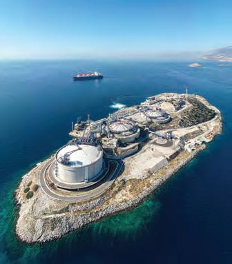
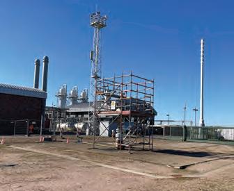
DESFA resumes Revithoussa LNG operations following equipment upgrade
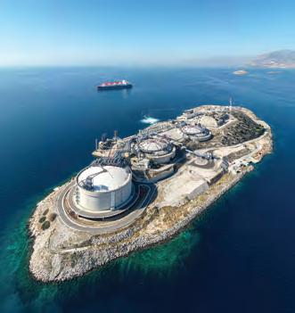
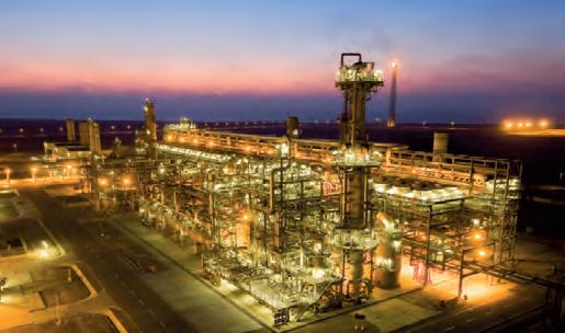
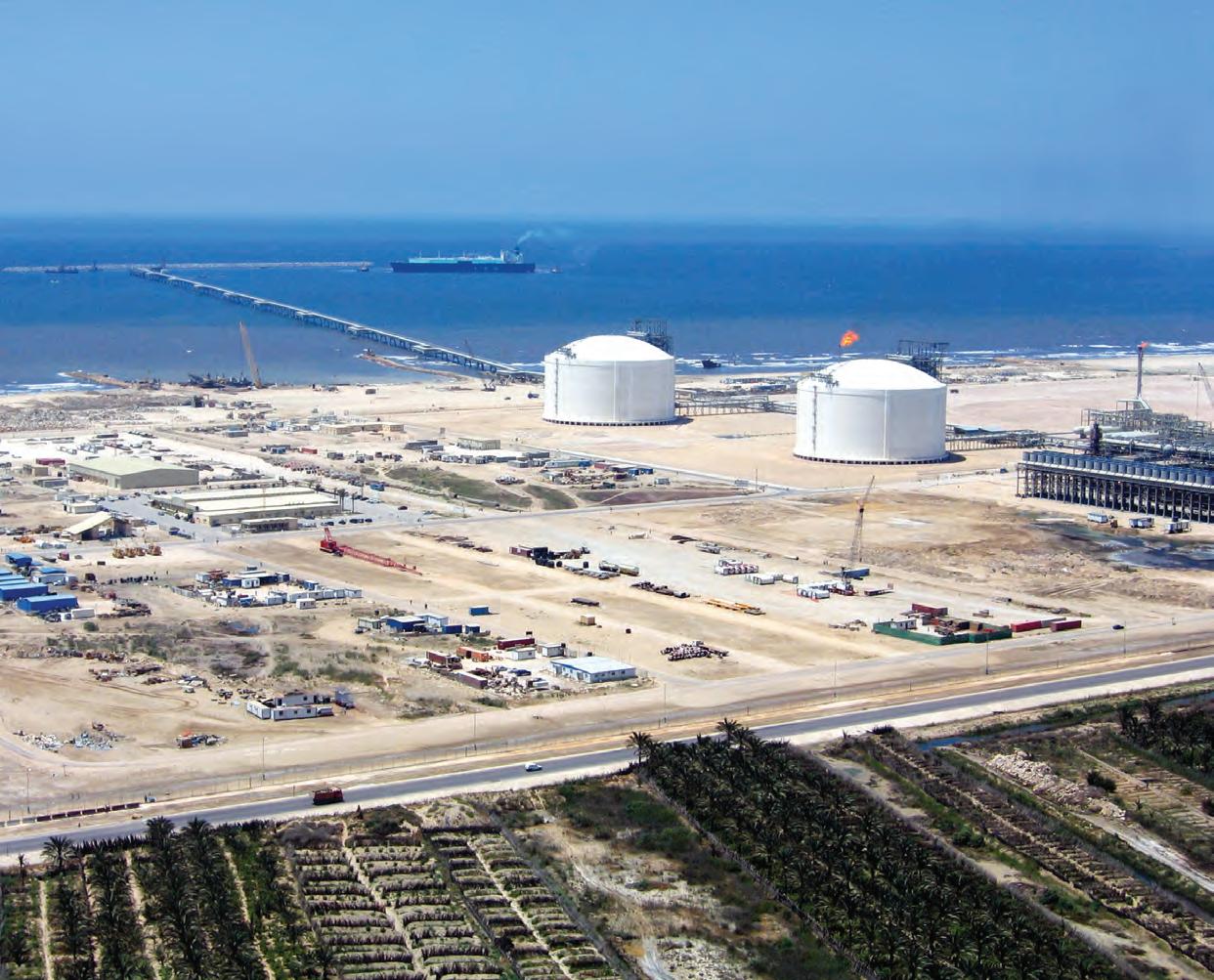
Greece’s DESFA has announced that operations have resumed at its LNG terminal in Revithoussa in mid-May following a planned shutdown to install a new highpressure boil off gas (BOG) compressor station.
Greece’s DESFA has announced that operations have resumed at its LNG terminal in Revithoussa.
The compressor station is expected to enter operation soon. Posting on LinkedIn, DESFA said that the station introduces a “sustainable way of managing boil-off gases by minimizing product losses.” The station will be capturing LNG vapors from the terminal’s tanks and injecting them into the high-pressure network. This is expected to result in the elimination of flaring from normal operations, turning Revithoussa into a zero-carbon dioxide (CO2) emissions terminal, according to DESFA.
located at a distance of about 20-30 km (12-19 miles) along the pipeline route and equipped with remote actuation and control systems. The preliminary studies also estimate that three compressor stations will be required, located in Coreses (Zamora),
Tivissa (Tarragona) and Villar de Arnedo (La Rioja).
Enagas said it had launched the conceptual engineering for the hydrogen network and had already awarded the contracts for the basic engineering of the
compressor stations and hydroproducts.
UK
Saipem wins compression station work for Liverpool Bay CCS
Italy’s Saipem has been awarded a contract by fellow Italian firm Eni for the Liverpool Bay carbon capture and storage (CCS) project in the Irish Sea offshore Northwest England.
Liverpool Bay CCS is one of the key projects underpinning HyNet North West, which is among the first two CCS clusters to be funded by the UK government as part of an industrial decarbonization plan. HyNet’s CCS infrastructure will be used to capture emissions from various industries in Northwest England and North Wales for sequestration in depleted offshore natural gas fields in Liverpool Bay.
Construction on Liverpool Bay CCS was approved in late April. Since then, Eni has secured a number of contractors, including Saipem, to help build various components of the CCS project. CT2
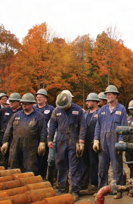
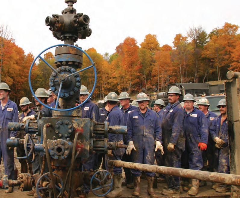
What Marcellus and Utica can offer
What initially seemed like a failed exploration project in the early 2000s ultimately uncovered one of the most significant natural gas discoveries in the world—and helped turn the U.S. into the top global producer of natural gas.
In 2003, a team from Range Resources drilled the Renz #1 well in Mt. Pleasant Township, Washington County, Pennsylvania. The initial target was the Trenton Black River formation, located about 200 feet below the Marcellus Shale. After several unsuccessful pilot attempts, the well was plugged, and the Marcellus remained untested and largely ignored.
Still, Range geologist Bill Zagorski— motivated by the success of shale development in Texas’ Barnett—saw promise in the Marcellus. In 2004, the Range team reentered the Renz well for a third time, completing what would become the first viable Marcellus Shale exploratory well. That experiment led to the discovery of the largest shale gas field in the U.S. and the fifth-largest in the world.
At the time, the U.S. Geological Survey (USGS) estimated recoverable gas from the Marcellus at just 2 trillion cubic feet (Tcf). By 2022, it had revised the estimate to 97 Tcf. Some industry observers believe the true
The biggest U.S. shale field helped make the nation the largest producer of natural gas.
By James Willis
number could be as high as 250 Tcf.
The Marcellus Shale lies roughly a mile underground across Pennsylvania, West Virginia, and parts of Ohio and New York. Below the Marcellus, at roughly twice the depth, sits the Utica/Point Pleasant formation—another prolific source of natural gas and liquids.
Opportunities and challenges
As exploration and production (E&P) companies began leasing acreage and delineating the Marcellus and Utica plays, it became clear the region held an extraordinary bounty of natural gas. However, unlike drilling in the Southwest, Appalachia’s E&Ps encountered intense resistance from environmental groups. With legislative options limited, opposition groups
turned to regulatory and legal tactics— successfully delaying or blocking new pipeline infrastructure vital to transporting gas to market.
After an initial wave of projects, building new greenfield transmission pipelines became nearly impossible. The most recent major success, the 303-mile Mountain Valley Pipeline from northern West Virginia to southern Virginia, took a decade to complete and ultimately required an act of Congress.
The resulting lack of pipeline takeaway capacity has constrained new production across the region. As supply outpaced infrastructure, prices crashed—often making the Marcellus/Utica one of the lowest-priced gas markets in North America.
Now, however, renewed demand from emerging sectors—particularly data centers
UTICA AND MARCELLUS SHALE PLAYS
Source: U.S. Energy Information Administration
Shale Play ■ Utica ■ Marcellus
■ Marcellus/ Utica Overlap
The Marcellus and Utica plays offer a bounty of natural gas..
powered by artificial intelligence—is sparking fresh interest in Appalachia’s massive natural gas resources.
COMPRESSORTech2 contacted and reviewed recent public statements from leading operators in the Marcellus and Utica to gain insight into how they view the region’s outlook today.
EQT Corp.
EQT, the largest pure-play operator in Appalachia and the second-largest gas producer in the U.S., currently produces 6.2 Bcfe/d—94% of it natural gas.
CEO Toby Rice responded to CT2’s inquiry with a focus on infrastructure challenges and the future of gas in powering digital infrastructure:
“We’re producing record amounts of
energy here in America, yet energy bills are up over 35%, and too many Americans continue to struggle. Simply put, we’ve seen political forces overcome market forces in recent years, preventing our most affordable, reliable and cleanest energy from getting to the marketplace.
“The Marcellus is an amazing story that illustrates the challenges we’re seeing across the country—the anti-pipeline movement that began in 2018 stalled production in the Appalachian region, further hindering that energy from reaching our customers.
“The region has tremendous energy potential in addition to unique access to vast industrial demand, a skilled workforce and strong technological capability. The AI boom is only accelerating power demand, and gas can meet it faster than nuclear. Speed to market matters, and the MarcellusUtica region is well positioned to meet the growing AI-driven need.”
Infinity natural resources
Founded in 2017, Infinity Natural Resources (INR) recently went public with a $265 million IPO, giving the company a $1.18 billion market capitalization. INR holds 123,000 net acres—about evenly split between the Ohio
Utica and the Pennsylvania Marcellus—and currently produces 153.7 MMcfe/d.
CEO Zach Arnold highlighted several opportunities and challenges:
Opportunities:
■ Power demand: Arnold sees AI and data center-related power generation as the biggest opportunity. “Each of these power plants that convert to gas can chip away at the narrative that this is a constrained basin.”
■ Commodity switching: The ability to produce both liquids and dry gas allows E&Ps to optimize drilling based on market conditions without relocating to a new basin.
■ Community support: Despite some organized opposition, Arnold noted that “most people in the region recognize the value and benefit of what shale energy can do.”
■ Low emissions: Increased use of field gas for electric fracking reduces emissions, traffic, and noise.
Challenges:
■ Pooling/unitization: Arnold praised Ohio’s unitization process for providing development certainty. Pennsylvania lacks a similar framework, creating stranded tracts and inefficiencies.
■ Permitting: Air permitting in particular can be a bottleneck, slowing efforts to add wells or optimize facilities.
■ Water reuse: Regulatory inflexibility makes recycling produced water more difficult, even when it would be environmentally beneficial.
Coterra Energy
Formed by the 2021 merger of Cabot Oil & Gas and Cimarex Energy, Coterra produces 2.2 Bcf/d from its northeast Pennsylvania Marcellus assets. Though it had shifted capital to the Permian in recent years, the company is redirecting investment back to the Marcellus.
During a recent earnings call, Coterra executives cited strong interest in power generation deals and the possible revival of the Constitution Pipeline. CEO Tom Jorden said:
The oilfield services crew that frac’d the historic Renz #1 well in October 2004 in Washington County, PA.
“There’s really not a significant limit [on Marcellus investment], but the Constitution Pipeline has been in the news… We would make a commitment to deliver long-term volumes into that line. That’s coloring what we want to do right now. We think that issue will resolve itself in the next few months.”
Expand Energy
Formed by the merger of Chesapeake and Southwestern Energy, Expand is the largest U.S. gas producer at 6.79 Bcfe/d. About 61% of its production comes from Appalachia, mostly dry gas from northeast Pennsylvania.
COO Josh Viets emphasized the company’s enthusiasm for AI-driven power demand, and the ongoing importance of LNG exports:
“We believe the world is short of affordable, reliable, low-carbon energy. The combination of LNG exports and power demand creates a unique opportunity for Expand.”
While the Haynesville remains the company’s LNG focus due to Gulf Coast proximity, Appalachia holds its highestquality rock. The Marcellus, Viets said, “could probably be characterized as the most prolific dry shale gas reservoir in North America.”
Takeaway constraints remain an issue. EVP Dan Turco noted:
“Appalachia has a clear need for
takeaway… we’re in active discussions with power demand producers and data centers. It’s good to see the conversation turning toward infrastructure again.”
Antero Resources
Antero, the largest gas producer in West Virginia, operates 500,000 net acres and produces 3.4 Bcfe/d—two-thirds of it gas, the rest NGLs.
SVP Justin Fowler pointed to the scale of the Marcellus/Utica and supportive state policies as key advantages. On a recent call, he said:
“The extensive resource base of the Marcellus and Utica Shales provides certainty of long-term supply… Recent announcements like the Homer City and CPV Shay power plants will add nearly 1.2 Bcf of regional demand.”
West Virginia is also encouraging behindthe-meter gas-fired power for data centers. A new “Microgrid Bill” incentivizes on-site
power generation—an emerging trend in data center development.
CFO Michael Kennedy noted processing and firm transport are currently at or above nameplate capacity: “If more local demand comes online, we can fill it easily—but we need the infrastructure.”
Encino Energy
Encino Energy, founded in 2011, acquired Chesapeake’s Ohio Utica assets in 2018 and is now Ohio’s top oil producer. After years of struggling to produce oil from the Utica/Point Pleasant, Encino succeeded where previous operators failed.
CEO Hardy Murchison said in a December 2024 interview that the long-term potential of the Utica is still being uncovered. With the ability to produce both oil and gas—and growing interest from power consumers—the Ohio Utica may play a larger role in the next phase of Appalachia’s development. CT2
The Waukesha VHP ® Series Five delivers superior power, 10% lower CO₂e and 85% lower CH4 emissions than any other engine in its category. Available in options from 750HP to 2,500HP, the Waukesha VHP ® Series is your first step toward a more powerful future.
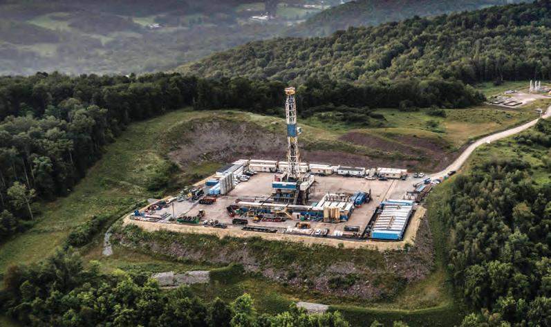
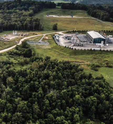
Expand Energy’s operation in Ohio and West Virginia target the Marcellus and Utical shales.
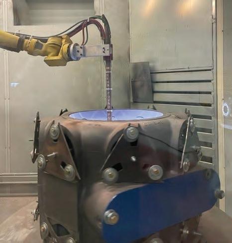
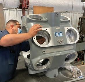
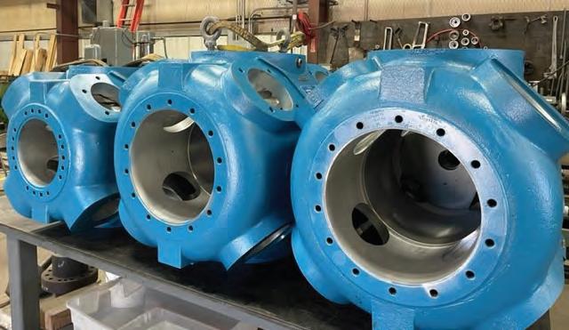
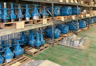
CENTURIES OF CRAFTSMANSHIP
ONE VISIONARY FUTURE
FIELD SERVICE
Your reliable partner for turnarounds, strategic planning, and maintenance, ensuring minimal downtime during overhauls and swift emergency responses with top-quality, safety-focused crews.
With our team of specialists and strategic partnerships, we deliver innovative and optimized performance solutions, including re-engineering, retrofit, modernization and other technical services.
We provide turn-key on-site and shop repair services for pumps, compressors, turbines and gearboxes.
PARTS REPAIR
Our experts manufacture and source parts to keep your machinery running in high health. We manage parts inventory and supply spare parts kitting.
GPA Midstream’s Sarah Miller focuses on advocacy, engagement and the future of energy
GPA Midstream and GPSA President and CEO
Sarah Miller is focused on regulatory advocacy, member outreach, and positioning the industry for long-term success.
By Jack Burke
Since taking the helm of GPA Midstream Association and GPSA in September 2024, Sarah Miller has concentrated on sharpening the organizations’ advocacy efforts, strengthening member engagement, and preparing the midstream sector for a rapidly evolving energy landscape.
Miller has a background as an industry attorney, corporate leader, and as longtime general counsel for GPA Midstream COMPRESSORTech2 recently spoke with Miller about her priorities for the association. The following is a condensed Q & A based on that conversation.
WHAT EXCITES YOU MOST ABOUT LEADING GPA MIDSTREAM AND GPSA AT THIS PIVOTAL TIME FOR THE INDUSTRY?
It’s an exciting time to be part of energy, period. There’s so much going on right now that will lead to innovation and solutions to the challenges we’re facing. I consider myself an optimist, and I look at how far we’ve come due to the creativity and expertise in this industry. I believe we have the right people to take us even further. We’re clearly in an “energy addition” world—we need more of everything to meet growing demand. Beyond that, there’s a push for energy security and reliability. We also have global issues like energy poverty that we can help solve. GPA Midstream and GPSA, in our niche of the industry, play a critical part in supporting the infrastructure that makes this all possible. That’s exciting.
HOW DO YOU DESCRIBE THE ROLE GPA MIDSTREAM AND GPSA PLAY IN THE BROADER ENERGY ECOSYSTEM?
I often start by explaining what midstream is, because people tend to be more familiar with upstream—exploration and production—or downstream, like utility gas lines or power plants. Midstream is everything in the middle. We’re talking about gathering pipelines that collect gas from wells and processing plants that separate dry gas from natural gas liquids (NGLs). Our members handle that.
Midstream isn’t limited to natural gas. We also touch crude oil and NGLs that are used in countless everyday products. GPA Midstream and GPSA support the operators and suppliers who make this part of the value chain work—and that backbone is essential for delivering reliable energy.
AT A RECENT INDUSTRY EVENT, THE KEYNOTE MENTIONED THAT THE INDUSTRY DOES ITS JOB SO WELL BEHIND THE SCENES THAT THE PUBLIC OFTEN DOESN’T REALIZE WHAT’S INVOLVED. HOW IS GPA MIDSTREAM WORKING TO CHANGE THAT?
That’s a great point—and we’ve called ourselves the “invisible industry” for that very reason. We’ve done such a good job keeping the lights on that people don’t realize how it happens. Many of us are engineers who put our heads down and solve problems logically, assuming the value
Miller took the helm of GPA Midstream in September 2024.
2025 GPA MIDSTREAM SCHOOL OF GAS CHROMATOGRAPHY
The 50th annual week-long training, designed, managed and conducted by GPA Midstream’s Analysis, Test Methods & Product Specifications Committee.
WHEN: Aug. 11–15
WHERE: University of Texas at Arlington PROGRAM HIGHLIGHTS:
■ Hands-on curriculum for chromatograph operators, measurement technicians and engineers
■ Industry-led, on-machine demonstrations and operation
■ Analysis of natural gas and natural gas liquid samples, plus an introduction to extended analysis
REGISTER: tinyurl.com/fcxpmnzx
is obvious. But we’re realizing we need to reveal ourselves more.
We have a federal advocacy program in Washington, D.C., where we work to educate lawmakers and regulators. We host site tours, provide technical comments, and explain how regulations affect realworld operations. We also offer an “Intro to Midstream” training course twice a year, which we’re now planning to host in D.C. to make it more accessible to decision-makers.
Another key initiative is our Let’s Clear the Air campaign. It’s a fact-based educational outreach effort aimed at the “movable middle”—those who are scientifically curious and want to understand where their energy comes from. We’re not targeting the political extremes, just people who want solid information to make informed decisions as voters, consumers, and citizens.
WHAT DOES THAT OUTREACH LOOK LIKE IN PRACTICE? HOW DO YOU CONNECT WITH THE GENERAL PUBLIC?
For the Let’s Clear the Air campaign, we created an ad series that follows a fictional
character named Pete, a midstream operator, through a day in his life. It uses “scrollytelling”—you scroll through the story on your phone, and it shows how Pete’s day intersects with everything midstream enables, from his toothpaste to his smart phone.
It’s designed to be approachable, educational, and factual . We use reliable sources like the U.S. Energy Information Administration. And we welcome feedback— even from skeptics—because it opens the door for dialogue. If someone challenges us on our claims, we can point to the data and have a real conversation.
HOW IS GPA MIDSTREAM HELPING TO TRAIN AND ATTRACT THE NEXT GENERATION OF WORKERS?
Our members rely on us for technical training. In addition to the “Intro to Midstream” class, we offer training on the Engineering Data Book—an industrystandard reference that’s been around for decades. It’s now cloud-based and continually updated by our editorial board of member experts. I’ve met people who still have their first Data Book from college on their shelf. That’s how essential it is.We also host the spring Technical Conference and the annual GPA Midstream Convention in September with educational forums and strong networking opportunities. Beyond formal training, our committee structure brings together everyone from senior leaders to new professionals. We even offer designated “young professional” seats on technical committees so newcomers can learn directly from industry veterans. Importantly, the agendas for those committees come from our members. They’re solving real-world challenges, and we serve as the platform for that collaboration.
WHAT ARE SOME OF THE TECHNICAL CHALLENGES COMMITTEES ARE FOCUSING
ON?
Emissions are a big one. We have an emissions committee focused on how to accurately measure, understand, and reduce emissions. Our members want to be at the cutting edge of responsible operations. Emissions aren’t just an
environmental issue—they’re also a financial one. If you’re losing product to leaks or inefficiencies, that’s lost revenue. So, reducing emissions is good business.
WITH AI AND DATA CENTER GROWTH DRIVING MORE ELECTRICITY DEMAND—MUCH OF IT FROM NATURAL GAS—HOW PREPARED IS MIDSTREAM TO MEET THIS DEMAND?
I think we’re well positioned to help meet those needs. Natural gas currently provides about 43% of the electricity in the U.S. Many people don’t realize that electrification depends heavily on fossil fuels—about 60% of electricity generation comes from them. So even if we electrify everything, we still need natural gas to make that possible.
The challenge isn’t supply—we have abundant domestic gas resources. The challenge is infrastructure and permitting. Both producers and pipeline companies are making long-term investments. But if permitting is unpredictable or subject to endless litigation, it’s hard to justify those investments. That’s why we’re encouraged by federal efforts to review and improve permitting rules. We want to be part of those conversations. Our members live in the communities they serve—they care about safety, the environment, and reliability. We’re not an outside force. We are the community.
THE INDUSTRY HASN’T ALWAYS COMMUNICATED WELL. HAS THAT STARTED TO SHIFT?
I think so. Operators I’ve worked with or represented have always cared about doing the right thing. Yes, they make economic decisions—they’re businesses—but there’s a genuine commitment to safety, to environmental responsibility, and to earning the social license to operate.
And you’re right, communication is part of that. It comes back to education.
THERE’S BEEN A LOT OF CONSOLIDATION
IN THE INDUSTRY. HOW DOES THAT AFFECT GPA MIDSTREAM?
That’s a very real trend and one we’ve been watching closely. The “pie” of the industry isn’t necessarily getting smaller, but the slices are bigger. That means our benefits are spread across fewer companies, even though the work continues to grow. CT2
The tools required for condition-based monitoring
Traditional maintenance approaches may miss key warnings.
By Zachary Bennett,
Detechtion Technologies
Oil and gas operations rely on large fleets of natural gas compressors to keep product moving. Unplanned compressor failures or downtime can cost a fortune – a recent industry report found that an hour of downtime in oil & gas can cost nearly $500,000 (Source). Traditional maintenance approaches based on fixed schedules often miss early warning signs or waste resources servicing machines that don’t need it yet. In this context, condition-based monitoring has emerged as a game-changer for smarter, more reliable compressor maintenance. By using realtime data to drive maintenance decisions, operations leaders can empower their teams to fix issues before they escalate, reducing costly downtime.
Why condition-based monitoring matters for operations
Running compressors “to failure” or servicing
them strictly by the calendar is a risky and inefficient strategy. Condition-based monitoring (CBM) means continuously tracking equipment health indicators – such as pressures, temperatures, vibration, or performance metrics – and only intervening when those metrics indicate a problem is developing. The goal is to fix issues just in time before a failure, rather than too early or too late. This approach yields significant benefits for operators:
■ Avoiding unnecessary maintenance: Instead of over-maintaining on a calendar basis, work is done when data shows it’s needed, saving labor and parts
■ Preventing unplanned shutdowns: Early warnings from sensors allow teams to address conditions that would otherwise cause a trip or failure, thereby reducing compressor downtime and production interruptions
■ Improving reliability and safety: Technicians can monitor key parameters that warn of pending problems (e.g. high vibration or temperature) and take action to avoid major damage. This not only improves reliability but also reduces the safety risks of catastrophic failures.
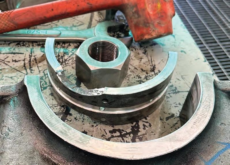
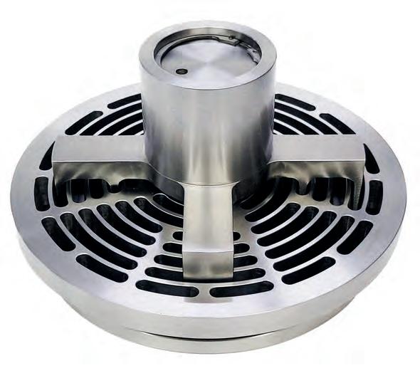
1
A damaged crankshaft “Big Side” bearing due to non-reversals as a result of operations beyond safe operating threshold.
■ Reducing costs: By minimizing surprise breakdowns and focusing maintenance where it’s needed, companies lower their overall maintenance spend and avoid the huge losses associated with outages In short, CBM helps shift maintenance from a reactive firefighting mode to a proactive, planned approach. Companies are increasingly striving for “management by exception”, where operators focus only on assets that signal a need for attention . Condition-based monitoring is the foundation of this strategy – it provides the visibility and alerts needed to know which compressors require intervention, and when.
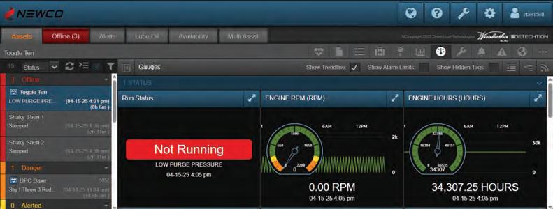
Real-time visibility: Catching Issues as they happen
The first piece of an integrated condition-based maintenance program is a robust real-time monitoring system that watches over compression assets 24/7. These are systems that integrate with compressor sensors and control systems to continuously capture operating
data (pressures, temperatures, run status, etc.) and sync it to a cloud dashboard. For operations leadership, this kind of fleetwide visibility is like “shining a big, bright spotlight” on your compressor operations
These systems provide immediate alarms and alerts when something is amiss. If a compressor shuts down or a parameter strays out of range, it will flag it in real time. In a pre-digital environment, crews often found out about problems late – sometimes by word of mouth or when a production drop was noticed. Now, with remote monitoring in place, the system notifies the team instantly. This means no more “driving blind.” You gain clear insight into what’s happening across miles of pipeline and dozens of unmanned stations.
Crucially, its alerting allows you to manage by exception. Your team’s attention is immediately drawn to the unit that needs care, rather than manually checking every asset. Automated alarm notifications tell you when to send someone to site and even hint at why the compressor went down. For example, an alert might indicate high discharge temperature on Compressor A, or that Compressor B has unexpectedly shut off due to low oil pressure. With this context, the dispatcher or supervisor can send the right technician with the right tools
While real-time monitoring is vital, data alone is not insight. This is where analytics comes into play.
to address the specific issue. This targeted response reduces unnecessary site visits and minimizes mean-time-to-repair, directly cutting downtime
Deeper
diagnostics with digital twin technology:
From data to insight
While real-time monitoring is vital, data alone is not insight. This is where analytics and digital twin technology come into play. These systems build on the data from monitoring systems to deliver deeper diagnostics and optimization for compressors. These systems use engineering models and algorithms to simulate compressor performance in software, side-by-side with the real unit.
By creating a digital replica of each compressor, operators can detect issues
that raw alarms might not catch. For instance, they can calculate performance indicators (like cylinder blowby, rod load, or flow capacity) and compare them to expected values. A slow decline in efficiency might signal a leaking valve or worn piston rings, and an abnormal pressure ratio could indicate a faulty temperature sensor or liquid in the line. It takes out the guesswork by pinpointing the likely causes of deviations.
In practical terms, these systems provide engineers and operations leaders with actionable recommendations. It might highlight that Compressor X is running off its design curve and suggest an adjustment to the separator or a cleanup of the intercooler, or that Compressor Y’s digital twin is predicting a valve failure in the next month, prompting a pre-emptive maintenance plan. By leveraging these insights, companies can schedule repairs at optimal times (avoiding surprise failures) and ensure compressors are running at peak efficiency. The analytics essentially guide a reliability-centered maintenance approach, where every maintenance action is backed by data. Over a large fleet, this can add up to significant gains – higher throughput, less fuel waste, and confidence that each compressor is doing its job safely and efficiently.
The human element: From alarm to action
Even the best digital tools rely on a skilled workforce to translate insights into results. Technicians, mechanics, and field operators form the critical human element of condition-based maintenance. When these systems indicate a performance anomaly, it’s these professionals who investigate on the ground and carry out the necessary fixes. Their expertise and intuition are irreplaceable – a vibration sensor might detect an imbalance, but an experienced mechanic determines if it’s a loosened mounting bolt or a failing bearing. Operations leadership should therefore view technology to empower and augment the workforce, not replace it. By giving teams access to better information, you enable them to be more effective
problem-solvers. For example, rather than doing routine “blind” inspections, a technician can arrive knowing exactly which compressor needs attention and why. Instead of hunting for a needle in a haystack, they start with a hypothesis driven by data (“Compressor 3 likely has a cracked plate on the second stage discharge valve – let’s check that first”). This makes their workflow more efficient and gets the equipment back online faster.
In summary, the human element works hand-in-hand with digital tools: sensors and analytics identify “what” and “when,” while skilled people figure out the “how” and execute the solution. By fostering a culture where your technicians and operators trust the data and proactively engage with it, operations leaders can multiply the impact of condition-based monitoring. Frontline ownership of asset health, supported by real-time intelligence, leads to smarter decisions at every level.
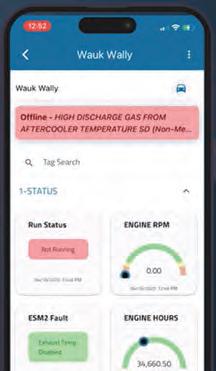
The rise of mobile applications
One of the latest advancements making condition-based maintenance even more effective is the advent of powerful mobile applications for the oilfield. Detechtion’s newly released Enbase Mobile app is a prime example of how to bridge the gap between remote monitoring and field response. In the past, receiving an alarm from a compressor often meant a text message or email alert that simply told an operator “Unit 12 Down – Engine Overspeed,” leaving them to log into a laptop for details. Enbase Mobile changes that paradigm by bringing a rich, native mobile experience right to the technician’s smartphone. With these mobile systems, critical alerts are pushed instantly to the phones of on-call staff as push notifications (no more waiting on SMS/email). The notification isn’t just a vague message – when tapped, it launches the app and takes the user directly to a detailed asset status screen for the affected compressor . There, the technician can see all the real-time readings and alarm details at a glance, just as they would on the control room dashboard. If a compressor is down, the app clearly shows the reason (e.g.
Condition-based monitoring enabled by integrated tools and a mobile-equipped workforce leads to better outcomes.
high vibration on Cylinder A) so the team member knows what issue they’re dealing with immediately.
Mobile applications also to help coordinate the response. For example, these apps can provide map-based directions to the compressor’s location in the field. This is incredibly useful for new technicians or contractors who may not know every site by memory – with one tap, they get turn-by-turn directions via Google or Apple Maps to reach the asset. By integrating mapping, the app helps save time in getting the right people to the right place as quickly as possible.
The result of these mobile capabilities is a much tighter connection between remote surveillance and field action. Field teams gain “fleetwide visibility at their fingertips,” no matter where they are. An operator out in the field can acknowledge an alert, see the context, and head directly to the troubled unit without detouring back to the office. Meanwhile, supervisors can track in real time which issues are being addressed. This level of connectivity translates to faster response times, better prioritization of work, and higher productivity from maintenance crews. In other words, it enables condition-based insights to travel with your people into the field, ensuring that no alert falls through the cracks. It truly bridges the last mile between digital monitoring and physical intervention, which is key to
realizing the full value of a condition-based maintenance strategy.
For operations leaders, adopting conditionbased monitoring isn’t just about installing new technology – it’s about enabling a more proactive and empowered maintenance culture. By integrating real-time monitoring and advanced analytics, and mobile tools for your workforce, you create a synergistic system where each component reinforces the other. Data from the field triggers the right actions, analysis informs smarter strategies, and people on the ground carry out fixes with greater confidence and speed. The payoffs are tangible: less unplanned downtime, longer asset life, and more efficient use of maintenance budgets. Companies implementing these practices have seen fewer failures and downtime hours – even as overall industry downtime costs remain high, those who invest in proactive maintenance can capture significant savings. Perhaps just as importantly, your team becomes more engaged. Technicians shift from being reactive “firefighters” to proactive problemsolvers who prevent fires from starting. Managers move from guessing what’s going on at far-flung sites to managing by exception with real-time insight into fleet health.
In conclusion, condition-based monitoring enabled by integrated tools and a mobile-equipped workforce allows operations leadership to run tighter, safer, and smarter operations. When you can spot issues early, diagnose them accurately, and dispatch resources immediately, you’re not just maintaining compressors – you’re optimizing them as critical assets. Downtime becomes the exception rather than the rule. By empowering your teams with these capabilities, you position your organization to deliver greater reliability and throughput, turning maintenance excellence into a competitive advantage. CT2
FIGURE 3 Powerful mobile applications help advance condition-based maintenance.
Norman Shade, in cooperation with KHL Group Americas and COMPRESSORTech2
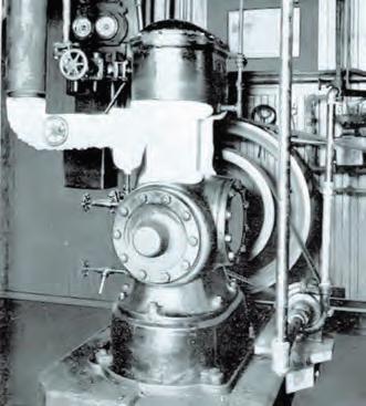
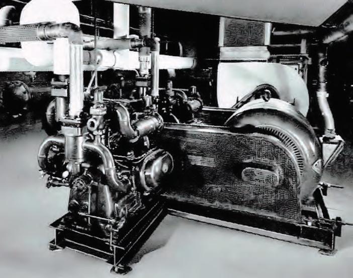
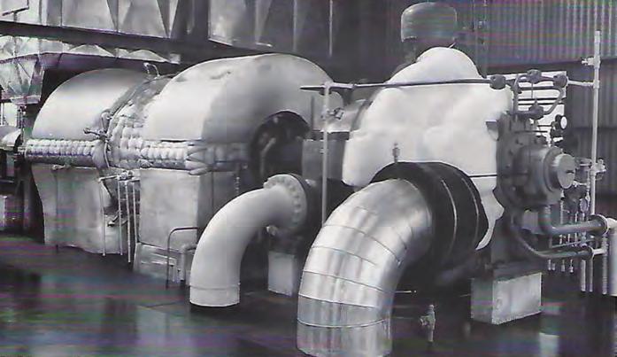
Published in October 2024, the primary objective of this book is to preserve the record of historically important compressors, engines and related technology and the companies that developed and manufactured them.
Norm Shade is the world’s leading expert in the gas compression industry, and this book is destined to be a classic and be a treasured resource for the industry with an infinite shelf life.
ORDER THE BOOK NOW
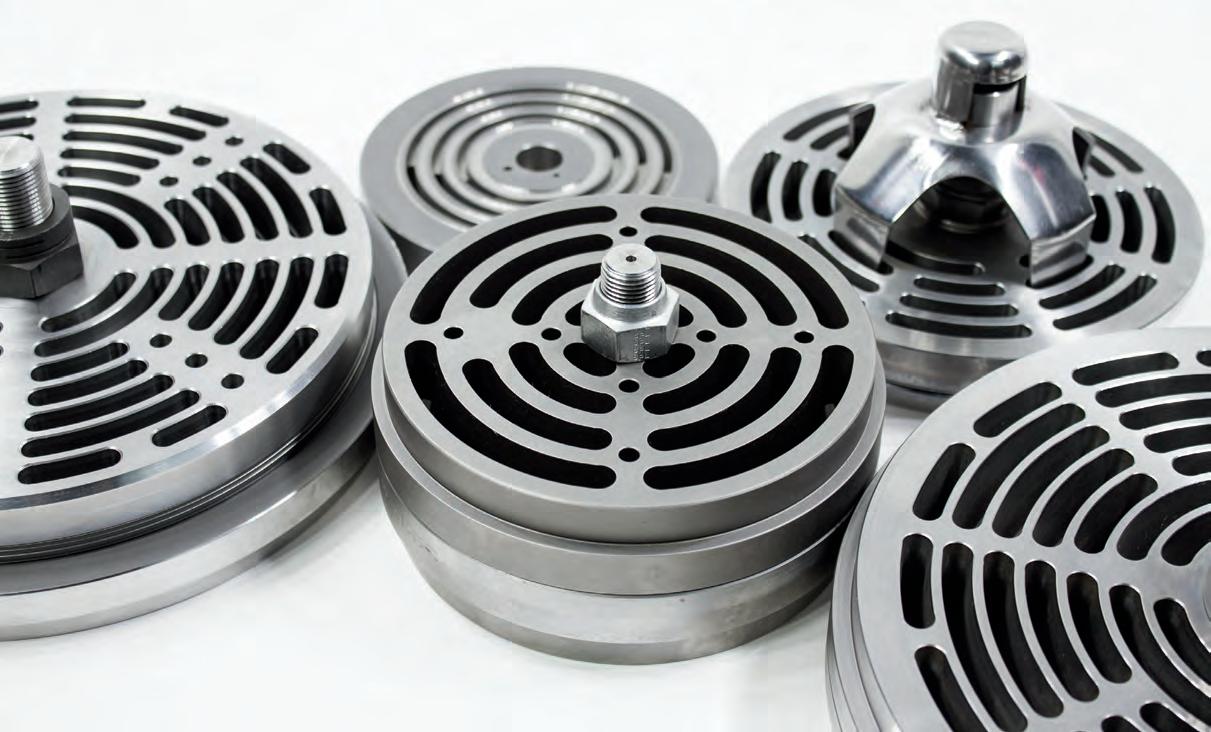
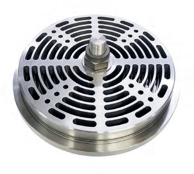
TAKING CARE OF ALL YOUR COMPRESSOR VALVE NEEDS.
24 hrs 7 days
Metallic Plates
Thermoplastics
Springs
Buttons
Poppets
Kits
Center Bolts
Pins
Lift Washers
O-Rings
Hydrogen systems, compressor valves, and spark plug reconditioning
take center stage in Galveston for GCA Expo event. By Jack Burke
Technology showcased at GCA Expo focuses on extending asset life, boosting efficiency
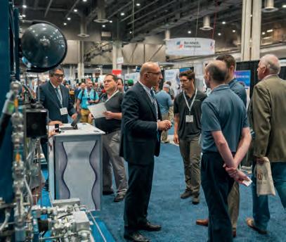
The 2025 GCA Expo & Conference in Galveston, Texas, brought together technology innovators focused on a common goal for the natural gas industry: improving equipment reliability, extending component life, and maximizing operational efficiency.
Across multiple technology categories, presenters at the 2025 GCA Expo emphasized modular design, field repairability, and performance tracking as key trends shaping the future of natural gas equipment. Whether optimizing current assets or preparing for future fuel flexibility, operators were offered solutions aimed at reducing total lifecycle cost and improving uptime.
Here are a few of the highlights from the Production Innovation presentations held at the event.
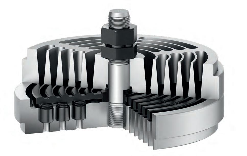
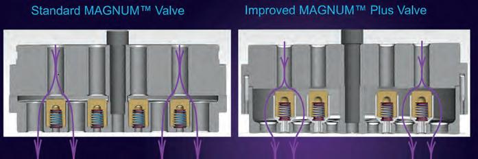
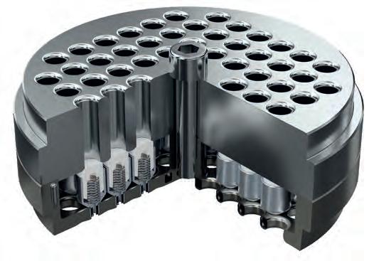
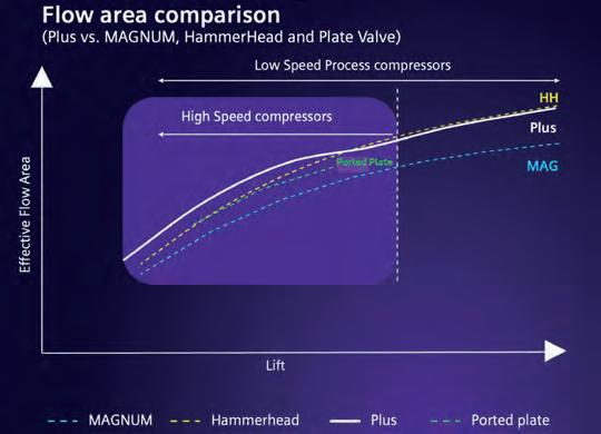
Siemens’ Magnum Plus valve
Siemens Energy discussed the Magnum Plus, its latest compressor valve design, aimed at increasing flow efficiency and extending mean time between service in high-speed reciprocating compressors.
Designed for both high- and slow-speed units, the Magnum Plus features a sturdier stop plate, increased flow area, and lower lift than previous Siemens models. “We’re expecting
run times of six to ten years on slow-speed units and three to five years on high-speed machines,” said Horacio Esteves of Siemens Energy. The valve’s modular design allows for field repair and easy replacement, even “on the tailgate of a truck,” he added.
Internal testing and live field deployments confirm that the new design enables more gas throughput with less wear, thanks to an optimized element density and robust structure.
Variable-speed fan clutch promises reduced maintenance and improved uptime
New pulley system targets diesel and natural gas engines in compression and transport applications: A new variable-speed fan pulley system developed by Horton Inc. aims to help operators of diesel and natural gas engines reduce maintenance, increase uptime, improve throughput, and cut emissions, according to company representatives at a recent industry event.
Dave Hennessy, a key representative at Horton, presented the company’s latest offering—an electromagnetic clutch-driven pulley system that offers precise thermal control for engine cooling fans. The system draws on decades of Horton’s experience supplying fan drives and clutches for on-road vocational and mining trucks.
“This technology is based on products we’ve been selling for decades,” Nuncity said. “We’ve purpose-designed the new clutch system to retrofit into existing machines with minimal intervention—essentially a drop-in replacement for traditional pulleys.”
Simple control, powerful benefits: The clutch connects directly to a 12-volt electrical system and commands fan speed through an intuitive control system. The clutch is failsafe, automatically reverting to full fan speed if electrical power or a sensor fails, ensuring reliable operation.
Allied Energy, GasPower showcase spark plug reconditioning system
Mark Hill of Allied Energy Group and Robert Virchow of European supplier GasPower presented a spark plug reconditioning program that they said offers a direct way for natural gas engine operators to cut maintenance costs and reduce waste.
By combining ultrasonic cleaning, professional gapping, and high-pressure test firing in nitrogen environments, the process can extend spark plug life by two to three maintenance cycles. Based on typical usage in a fleet of 250 engines, companies could save up to $17,000 per quarter using the system, according to Allied.
Each plug undergoes visual and thread inspection, precision re-gapping, and a high-fidelity test on a six-channel spark plug test stand, which fires plugs at 700 psi to confirm they’ll operate through the next PM interval. “The goal is to give each plug a second or third life while maintaining high reliability,” Hill noted.
The Magnum Plus valve.
Modular hydrogen systems
In the hydrogen space, Neuman & Esser and its Hytron division highlighted a new line of modular PEM electrolyzer systems designed for scalable hydrogen production and seamless integration into gas infrastructure and renewable power sources.
With configurations ranging from 50 kW to 5 MW per module, the electrolyzers are built into containerized platforms with globally standardized piping, while allowing for local customization in water purification and power electronics.
Hydrogen purity levels of 99.9% (standard) and up to 99.999% (with optional PSA and drying) can be achieved within the same footprint. CT2
INNIO Waukesha, Detechtion say SkidIQ Adapt unlocks hidden compressor value
New digital platform integrates real-time monitoring, digital twin control, and full-fleet optimization: INNIO Waukesha, in collaboration with Detechtion Technologies, said SkidIQ Adapt compressor management can unlock up to $250,000 in untapped value per compressor annually. Sarah Whitney outlined the benefits of the SkidIQ product suite and its transformative potential for natural gas producers.
“Compressors are the backbone of gas production,” Whitney said, “but they also bring challenges—avoidable downtime, underutilization, frequent shutdowns, and rising operating costs. SkidIQ is designed to tackle those issues head-on.”
From monitoring to optimization to autonomous control: The SkidIQ platform follows a three-stage model of evolution—Manage, Optimize, and Adapt. The system begins with SkidIQ Manage, which enables near real-time asset monitoring. That data then feeds into SkidIQ Optimize, which uses a compressor-specific digital twin to adjust performance parameters and reduce inefficiencies. One customer using SkidIQ Optimize improved uptime by adjusting suction pressure, leading to an annual production gain of $15 million and a $2 million reduction in operating costs—achieving return on investment in 63 days.
Adapt goes a step further: The latest stage, SkidIQ Adapt, brings full automation and real-time decision-making into compressor control. By integrating the compressor and engine into a unified control system, and deploying a digital twin at the edge, Adapt continuously calculates process variables and dynamically assigns optimal set points. “We believe SkidIQ Adapt represents a transformational shift in how we manage compressor fleets,” Whitney said. “It’s time to stop leaving value on the table.”
Neuman & Esser discussed scalable hydrogen.
Experts highlight compressor,
LNG growth fuels midstream demand, tech innovation. By
AJack Burke
s global demand for cleaner energy sources accelerates, liquefied natural gas (LNG) is emerging as both a strategic fuel and a driver of infrastructure growth across the midstream sector. COMPRESSORTech2 recently hosted a technical webinar exploring how LNG projects are evolving—and how compressor and turbine technology play a central role in achieving reliability, decarbonization, and operational excellence.
The speakers were two recognized experts in the LNG space. Vasant Saith, Vice President of LNG for Worley Consulting, Americas, brings more than two decades of global experience in engineering, construction, and project leadership across LNG and carbon capture. His work spans the entire LNG project lifecycle—from site selection to commissioning—and is helping shape the next generation of low-carbon energy infrastructure.
Joining him was Sanjeev Daruka, Head of Global LNG at Siemens Energy. With over 30 years of experience in rotating equipment
and gas turbine systems, Daruka is at the forefront of LNG process innovation. His team works closely with developers to deliver high-efficiency, low-emissions systems that are tailored for today’s LNG market—especially in mid-scale and floating applications.
Here are 10 key takeaways from the session:
1 LNG is driving sustained midstream infrastructure demand Natural gas remains the linchpin of the energy transition—and LNG is the vehicle taking it global. “We do consider natural gas to be that transition fuel…for decades,” said Saith. As LNG bridges traditional fuels and renewables, midstream infrastructure
“We do consider natural gas to be that transition fuel for decades.”
VASANT SAITH, Vice President of LNG, Worley Consulting, Americas.
will remain in high demand to link resources with global consumers.
2 U.S. LNG export capacity is primed to double
With LNG output already over 100 mtpa, the U.S. is poised to double exports by 2035. “A lot of the growth is coming through expansions,” said Saith, noting that permitted brownfield sites with proven operators are moving fastest. For midstream players, this means increasing throughput volumes and new connection points.
3 Compressors remain critical to project reliability and economics
“If the compressor goes down, everything goes down,” Saith emphasized. Refrigeration compressors, inlet boosters, and boil-off gas recovery systems are all essential to LNG operations—and represent key opportunities for midstream service, maintenance, and performance optimization.
4 Financing hinges on proven compression solutions
LNG developers and their financial backers prioritize trusted technology. “They already inform us who they think will make them most financeable,” said Saith. Midstream operators must consider
The full webinar is available here: www.compressortech2.com/news/webinar-lng/8056175.article
compressor, turbine roles in next wave
talk on mid-scale…[it’s] a quicker build approach,” said Saith.
7 Fast restart capability is essential for minimizing LNG downtime
In the event of a trip or upset, pressurized restart capability becomes essential.
“You do not want to depressurize the compressor to restart it,” said Daruka. High-torque turbines reduce refrigerant loss and speed recovery—a must for 24/7 operations.
8 Local maintenance and service capabilities add value
“Every customer wants the ability to maintain critical equipment locally,” said Daruka. Compressors and turbines that can be overhauled on-site reduce downtime, enhance regional job creation, and simplify O&M planning—key considerations in both
“Fuel gas flexibility is key,” said Daruka. Some upstream gas streams include elevated nitrogen levels, which can complicate liquefaction. Turbines capable of handling up to 25% nitrogen enable developers to accept a wider range of gas qualities—opening up new gathering and transport opportunities.
“Every customer wants the ability to maintain critical equipment locally.”
10 Low-carbon LNG is shaping market premiums and project design
“There’s increasing interest in lowemissions LNG,” said Saith. Premium buyers, especially in Asia, are willing to pay more for cleaner product. That’s
influencing turbine selection, power source decisions (electric vs. gas-fired), and the inclusion of CCS—all of which directly impact midstream project design and long-term commercial strategy. CT2
SANJEEV DARUKA, Head of Global LNG, Siemens Energy.
At World Hydrogen North America 2025, panelists share insights on infrastructure, technology, and policy needs for building a viable hydrogen economy. By
Jack Burke
Roundtable explores how to scale up hydrogen market development
As the hydrogen economy moves from vision to implementation, energy leaders are grappling with the complex realities of scaling clean hydrogen production and distribution. At the World Hydrogen North America 2025 conference in Houston, Texas, a high-level roundtable brought together key voices from across the hydrogen value chain to address a central question: How can we scale up hydrogen market development? Moderated discussions highlighted the urgent need for regional coordination, flexible infrastructure models, and
supportive policy frameworks to unlock investment and accelerate deployment. Speakers included Tina Moss, director of net zero business development at LyondellBasell; Dana Wong, senior manager of renewable and low carbon strategy at FortisBC; Andy Steinhubl, hydrogen program chair at the Center for Houston’s Future; and Sunny Punj, COO of CGI Gases. Each offered perspectives grounded in current project experience and market realities.
Pressing challenges
From regional hydrogen hubs and decentralized mesh networks to market confidence in emerging technologies, the conversation offered a multidimensional view of the industry’s most pressing challenges and promising opportunities. The insights captured here reflect the state of play for hydrogen in North America—and the critical steps required to move from pilot projects to large-scale, commercially viable solutions.
■ A primary driver of the US hydrogen hub program was to tackle regionally specific challenges — aligning producers, midstream players, and end users around a shared regional vision.
■ Gulf Coast examples include optimizing hydrogen production (blue and green) with low-cost natural gas and
TINA MOSS Director of net zero business development, LyondellBasell.
DANA WONG Senior manager, renewable and low carbon strategy, FortisBC.
ANDY STEINHUBL
Hydrogen program chair, Center for Houston’s Future.
SUNNY PUNJ COO of CGI Gases.
A hydrogen storage facility.
PHOTO: ADOBE STOCK
renewables, identifying natural export corridors, and addressing infrastructure gaps.
■ Most hydrogen pipelines today are proprietary; open-access infrastructure proposals are emerging, but cross-chain infrastructure development remains essential.
Tina Moss, Director, Net Zero Business Development, LyondellBasell:
“In the case of the greater Gulf Coast, let’s get those producers, midstream players, end users together and come up with a common vision… Here’s where it needs to move, the region. Here are the natural export corridors. What infrastructure do we need versus what do we have?”
2 Co-Locating Hydrogen Supply with Large Industrial Users
■ Directly placing hydrogen production near high-volume gas users (e.g. paper mills, mining operations) offers fast, costeffective climate impact.
■ While blending hydrogen into large-scale transmission systems is being studied, this will take years — so near-term decarbonization depends on local, purpose-built supply systems.
Dana Wong, Senior Manager, Renewable & Low Carbon Strategy, FortisBC:
“We really want to move the needle on climate — we need to target those large gas users so we can co-locate our supply right next to the user. That’s our strategy.”
3 Decentralized Mesh Networks & Advances in Transportation
■ Hydrogen’s distributed market requires a decentralized, mesh-like production network — with smaller-scale production sites within 150–300 miles of demand centers.
■ Advances in lightweight, high-pressure carbon-wrapped trailers are extending viable distribution distances to 500–700 miles, improving flexibility and lowering costs.
4 Market Uncertainty & Scaling New Production Technologies
■ Many customers remain skeptical of unproven production technologies, preferring established systems like SMR with CCUS.
Sunny Punj, CEO, GCI Gases:
“The biggest challenge… is that lack of confidence in the new technologies… Can they scale? Are they reliable?”
■ Even as promising technologies (e.g. chemical looping, methane pyrolysis) scale, commercial viability, reliability, and operational track records are essential to win market trust.
5 Blue Hydrogen’s Strategic Role & 45Q Incentives
■ Gulf Coast blue hydrogen, using low-cost natural gas and CCUS, can deliver globally competitive pricing while leveraging federal 45Q tax credits.
■ This extends US natural gas leadership and provides economic justification for bulk hydrogen infrastructure build-out alongside localized projects.
Andy Steinhubl, Hydrogen Program Chair, Center for Houston’s Future:
“If you’re looking at tax incentives… there’s 45Q, which gives credit to the capture of that carbon dioxide… The Gulf Coast has
completed and active reservoirs that lend themselves to CCUS, which allow us to produce, globally, very low-cost blue hydrogen.”
6 Methane Pyrolysis: Scalable, WaterEfficient, and Carbon-Solid Producing
■ Methane pyrolysis offers lower energy and water requirements versus electrolysis and produces solid carbon (graphite) — a value-added byproduct.
■ This decentralized, scalable technology supports co-location strategies and can rapidly deploy hydrogen in urban/industrial areas without pipeline retrofits.
■ Industry urgently needs clear, stable policies and market frameworks defining what qualifies as “low-carbon” hydrogen, especially for projects already underway.
■ The Open Hydrogen Initiative is developing carbon intensity measurement tools and standard contract terms (e.g. location, quality, CI factor), essential for transparent
“We still need some supportive government framework and policies and incentives to deficit technology and the deployment, and then we also need deep collaboration across the whole value chain.”
evenue Stacking and Cross-Chain Collaboration
Join us for a one-hour webinar on the growth of liquefied natural gas (LNG) as an energy source. The webinar will discuss solutions to some of the key technical challenges in the LNG value chain. Join us for a one-hour webinar and explore the role of compression in carbon capture and storage.
Successful project financing increasingly depends on revenue stacking: combining hydrogen sales, tax credits, CCUS incentives, and value-added byproducts. Deep collaboration across the hydrogen value chain — from production to demand centers — is crucial for ecosystem development and faster decarbonization.
Steinhubl:
Vasant Saith Vice President, LNG & CCUS at Worley Sanjeev Daruka Head of Global LNG, Siemens Energy
“There’s an initiative… called the Open Hydrogen Initiative that’s working on a carbon intensity tool and standards, so that everyone knows what they’re getting when they’re buying hydrogen.” CT2
With our HOERBIGER Profiled Plate Valve Series, you get both proven reliability and better performance.
Optimized for higher speed compressors with larger bore cylinders , our CP valve’s unique design and features provide maximum reliability and efficiency.
With more than ½ million valves in the field today, HOERBIGER profiled plate valves are the global standard and preferred choice. In fact, one in every three high speed compressors in your natural gas fleet is likely using our profiled plate valves right now. And if not, they should be.
Our Profiled Valve Series are the best valves available today. For a better tomorrow.
Learn more by visiting www.hoerbiger.com/cp today!
2025
JUNE
Global Energy Show Canada
June 10-12
Calgary, Canada Globalenergyshow.com
ASME TURBO EXPO
June 16-20
Memphis, Tenn. Events.asme.org
Hydrogen Technology Expo N. America
June 25-26
Houston, TX Hydrogen-expo.com
SEPTEMBER
Gastech Expo
Sept. 9-12
Milan, Italy www.gastechevent.com
TURBOMACHINERY & PUMP SYMPOSIA
Sept. 16-18
Houston, Tx. Tps.tamu.edu
GPA MIDSTREAM
Sept. 21-24
San Antonio, Tx. www.gpamidstream.org
GMC
Sept. 28-Oct.1
Louisville, KY
www.gmrc.org
EVENTS & MEETINGS DIARY DATES
OCTOBER
OTC Brazil
Oct. 28-30
Rio de Janeiro, Brazil
Otcbrasil.org
EFRC CONFERENCE
Oct. 14-16
Hamburg, Germany
www.recip.org
NOVEMBER
ADIPEC
Nov. 3-6
Abu Dhabi Adipec.com
JANUARY
ADI Forum
Jan. 28-30, 2026
Houston, TX
www.adi-forum.com
POWERGEN
Jan. 20-22, 2026
San Antonio, TX
www.powergen.com
MARCH
OTC Asia
March 31-April 2, 2026
Kuala lumpur, Malaysia Otcasia.org
BOLDFACE indicates shows and conferences in which COMPRESSORTECH2 is participating
For a complete listing of upcoming events, please visit our website: www.compressortech2.com/events
www.compressortech2.com
New flow-through valve design targets improvements in reciprocating compressor efficiency, reliability, and serviceability
By Joel Sanford and David VanKirk
Over the last three decades, original equipment manufacturers (OEMs) have dedicated significant time and resources toward improving the design of reciprocating compressors valves, and rightfully so. Multiple studies have shown that among all compressor components, valves are the leading cause of unplanned downtime. Valve design and configuration also directly influences a compressor’s energy efficiency, maintenance schedule, and turndown capabilities.
The introduction of the MAGNUM™ valve in the late 1990s marked a milestone in compressor valve development by setting a new standard in terms of industry reliability and efficiency.1 Additional improvements were realized in 2012, with the release of the MAGNUM Hammerhead valve, which features a higher effective flow area (EFA), translating to lower energy losses and increased compressor efficiency.
Siemens Energy has now taken the next step in valve design by introducing the MAGNUM™ Plus, which combines proven features of the standard MAGNUM and Hammerhead concepts, along with new innovations to meet evolving operator requirements for higher compressor uptime, reduced power consumption, and lower OPEX.
MAGNUM Plus design overview
The MAGNUM Plus can be installed in any brand or configuration of reciprocating compressor and supports speeds up to 1,800 rpm and differential pressures up to 3,000 psi. It is designed for gases of any molecular weight but is particularly well suited for hydrogen applications, which put unique demands on compressors in terms of efficiency, reliability, and in some cases (such as electrolysis plants), flow flexibility.
Advanced computational fluid dynamics (CFD) and finite element analysis (FEA) were employed to develop the MAGNUM Plus valve’s unique geometry. Figure 2 above shows the cross section of both the standard MAGNUM and the new MAGNUM Plus valve design. As seen, the main differentiator of the MAGNUM Plus is that valve elements are no longer moving in the stop plate. The framing component for the axial movement of the valve element is now a cup (pocket), which is threaded into the stop plate.
This unique component design decouples the outlet flow area from the valve element functional area, increasing the EFA on the outlet side, while simultaneously enhancing the EFA within the valve functional area. Although the new concept increases the overall height of the build, it comes with
the benefit of higher gas throughput. Additionally, the ratio of valve elements to valve diameter has been increased, as has the number of outlet flow holes. Figure 3 shows a top view of a standard MAGNUM (left) versus the MAGNUM Plus (right).
Reducing compressor power consumption
Valves play an important role in a compressor’s overall efficiency. An optimized valve design allows the compressor to deliver the highest flow rate of gas at the desired pressures by consuming the least amount of energy. Maximizing the valve orifice or EFA is key in this regard, as it results in less flow restriction and pressure drop, and lower power consumption.
Minimizing power consumption is desirable in all compressor applications. However, it is especially critical in proton exchange membrane (PEM) electrolysis (i.e., green hydrogen) plants that rely on intermittent power sources, like wind and/ or solar.
Another design factor that impacts efficiency is valve clearance. As valve
FIGURE 2. FLOW PATH OF STANDARD MAGNUM (left) VS. MAGNUM PLUS (right)
FIGURE 3. TOP VIEW OF STANDARD MAGNUM (left) VERSUS THE MAGNUM PLUS (right)
FIGURE 1. MAGNUM™ PLUS VALVE COMBINES
FEATURES OF THE STANDARD MAGNUM AND MAGNUM HAMMERHEAD VALVES
clearance increases, compressor flow is reduced. The MAGNUM Plus valve, with its relatively small moving element and optimized distance between elements, is specifically designed for low clearance, yet has an EFA higher than the standard MAGNUM and equal to that of concentric ring valves.
The valve lift configuration also influences EFA. A higher EFA can be achieved by increasing valve lift, but only up to a certain limit. The geometric characteristics of each valve type determine this limit of lift, beyond which more flow area cannot be obtained. Laboratory tests measure the flow coefficients at various lifts, allowing flow areas to be obtained for each valve type.
Figure 4 shows EFA flow test results from a MAGNUM Plus valve versus other common valve designs. As seen, the MAGNUM Plus exhibits the highest EFA in low lift configurations, which are representative of hydrogen compression applications.
In 2024, a MAGNUM Plus valve was installed as part of a pilot project in a reciprocating compressor serving a hydrogen plant (refinery application). The performance of the compressor was compared with a second identical compressor in the plant which utilized only standard MAGNUM Valves.
Over the course of nine months (~7,000 hours of runtime), horsepower was measured by an independent thirdparty on three occasions. The test results showed a 1.6% reduction in power loss using the MAGNUM Plus, which was consistent with theoretical calculations performed by Siemens Energy’s design team.
Meeting requirements for increased valve reliability
Although efficiency is becoming a more important performance metric for many end-users, valve reliability has remained the top priority across virtually every compressor application.
The moving elements in the valve are subject to stresses imposed by differential pressure (DP) and impact forces. The moving element must be strong enough to resist the impacts and DP force when it is closed against the valve seat, as well as
impact forces when it is opened against the stop plate.
As valve lift increases, so too does the impact velocity when the element returns to the seat or stop plate. This creates stress and accelerates wear and tear on valve components, including the seat and sealing elements. The causal relationship between valve travel distance and decreased valve life is widely known and has been the focus of several studies over past decades.
Reducing valve lift is advantageous. However, as previously discussed, doing so also reduces EFA, leading to higher pressure drops and increased energy losses.
A key advantage of the MAGNUM Plus valve is that its unique geometry and design increases EFA without a corresponding increase in lift. The travel distance of the MAGNUM Plus element is approximately one-third lower than a standard MAGNUM element in the same compressor configuration.
Other notable features which have been incorporated to support longer valve runtimes include:
● “Open” design concept to reduce particle build up
● Bottom bevel added to reduce point stress and prevent fractures associated with flat contact surfaces
● Multi-poppet design is tolerant against over-lubrication, liquid carry over, and will continue to function with damaged elements
● Corrosion resistant valve spring materials
● Proven materials used for stop plate (Nodular Iron, 17-4PH SS, SAE AISI 4140)
● Low stress spring design
Siemens Energy anticipates that these features will support extended run times versus previous valve designs.
Designed for serviceability
Serviceability is an important factor to consider in the context of a compressor’s total cost of ownership (TCO).
To support ease of maintenance, the MAGNUM Plus valve utilizes threaded cups which hold the valve elements. If either a valve element or a cup becomes worn, the threaded cups can be unscrewed and replaced. The procedure can be performed quickly (i.e., in a matter of minutes) and requires no special tools or training, as would typically be required with other valve types.
Additionally, unlike plate and ring valves, the MAGNUM Plus valve uses a single element for all valve sizes, which simplifies inventory management.
Continuously improving
Established designs like the standard MAGNUM and MAGNUM Hammerhead valves continue to meet and exceed the requirements of operators across a broad range of industries. However, with new compression applications emerging to support various decarbonization use cases, particularly in the context of hydrogen, the demands being placed on reciprocating compressors are evolving. This, in turn, has created a need for innovations in valve design.
The MAGNUM Plus was designed to address this need and represents the next step in valve development by combining many proven characteristics of past MAGNUM variations with novel features aimed at incrementally improving compressor efficiency, uptime, and serviceability.
REFERENCE: 1 J. Sanford, S. Chaykosky. Valve performance: A key element for reliability and efficiency of reciprocating compressors in hydrogen applications. COMPRESSORTech2. March 2023.
FIGURE 4. FLOW AREA COMPARISON OF DIFFERENT VALVES
SHORT COURSES: SEPTEMBER 15, 2025
SYMPOSIA: SEPTEMBER 16-18, 2025
GEORGE R. BROWN CONVENTION CENTER | HOUSTON, TX
The Turbomachinery & Pump Symposia is recognized worldwide as the industry’s must-attend event. Connect with over 4,700 delegates, meet with leading suppliers, observe product demos, and get answers to your technical questions.
We look forward to seeing you in Houston!
4,768 ATTENDEES 48 COUNTRIES 298 EXHIBITING COMPANIES
HOSTED BY
Protecting dynamic compressors
By Roman Bershader
The applications of dynamic compressors can be divided into three main groups:
1 Aircraft engines, where axial compressors predominate;
2 Turbochargers for gasoline and diesel automobile engines, which use small centrifugal compressors rotating at very high speeds;
3 Industrial compressors, which can be used in a wide range of industries, vary in types and sizes depending on the tasks they perform: from compressed air for blast furnaces to compressed gas for oil refining or liquefaction of natural gas, etc. All dynamic compressors have unstable operating modes known as surge, rotating stall, and choke, which are still the subject of debate, since the nature and causes of their occurrence are unclear. However, such operating modes must be avoided or prevented to protect the equipment and not disrupt normal operation. It should be noted that balancing tests of compressor rotors are usually carried out under vacuum conditions. In such conditions, neither surge,
AUTHOR
In 1978 ROMAN BERSHADER graduated from the Kazan Aerospace Technical School with a master’s degree. In 1984 defended his Ph.D. thesis in the field of fluid mechanics in Moscow at the Institute of Water Problems. Immigrated to the United States in 1989. US citizen. Prior to immigration, about 10 years of experience in experimental fluid mechanics at the Institute of Water Problems. Experience in the USA 30 years with Compressor Control Co.
nor rotating stall, nor choking occurs, which emphasizes their exceptional gas-dynamic nature.
Dynamic compressors work with a substance that is a gaseous form of matter, consisting of many molecules or microscopic particles that are much smaller than their average distance from each other and fill the entire space in which they are located. The interactions between molecules are assumed to correspond to the kinetic theory of gases, based on the ideal gas model, in which collisions are elastic and molecules with higher temperature, and therefore higher energy, transfer energy to neighboring molecules. The mechanical rotational effect on molecules with the aim of creating increased pressure occurs in accordance with the law of conservation of energy.
Motion of molecules
In fact, the operating principle of dynamic compressors can be represented by a simplified model in which gas molecules
are drawn into the compressor by rotating elements having a complex curvilinear shape, the purpose of which is to draw and push the molecules through a space of variable cross-sectional area, decreasing in diameter as the molecules move from the inlet to the outlet, as shown in FIG. 1.
Despite the apparent simplicity of the chosen model, the motion of molecules in the compressor is extremely complex. First, the Reynolds number at the compressor inlet is quite high (Re > 10^5), which characterizes the incoming flow as highly turbulent. Second, when the molecules come into contact with the rotating parts of the compressor, they are subjected to centrifugal forces, which impart rotational motion to them. The higher the point of contact of molecules with the blades or impellers, the higher their velocity, kinetic energy and temperature can be. Third, the formation of Karman vortex streets, which are unstable flow separations around stationary parts of the compressor in the form of swirling vortices. Therefore, the motion of molecules in three-dimensional space inside a compressor with constantly
FIGURE 1 Simplified model of a compressor.
changing gradients of velocity, temperature and pressure can exist only in the form of rotating clusters of molecules that are continuously formed, collide with each other, deform, and disintegrate. The entire process of formation and disintegration of such clusters, as well as their size, depend on the compressor design, shaft speed and flow rate.
In the molecular motion of intense vortex mixing, there are always areas of increased concentration of molecules, where their freedom of movement is strongly limited by the minimum distance between them, and the number of mutual collisions increases sharply with a more intense exchange of heat and kinetic energy, which brings the molecules into a state of vibrational excitation. Vibrations create pressure waves that move not mass, but energy propagating in all directions, which is the probable kinetic energy of vibrational motion at a given temperature. The magnitude of this kinetic energy, according to the MaxwellBoltzmann energy distribution, depends on the proportion of participating molecules. Wave interference can be observed in all types of waves, including pressure waves, which are superimposed in the compressor, forming a resulting wave that transfers its energy forward.
As molecules pass through the compressor, their mean square velocities alternately increase and decrease. With each increase in velocity, the kinetic energy of the gas increases, and with each decrease in velocity, the kinetic energy is converted into an increase in static pressure, which increases the probable internal energy of the static state of the gas. During normal operation of the compressor, according to the law of conservation of energy, the projections of all components on the direction of translational motion can be represented by the following equation:
EP in + KE + WE - EP out = 0 (1)
Where: EP in – probable internal energy of static state at the input; KE – probable kinetic energy of translational motion of molecules; WE – probable kinetic energy of the vibrational motion; EP out – probable
internal energy of static state at the output. However, there are abnormal operating modes of the compressor, in which the collisions of a significant number of molecules cease to be elastic, which leads to a sharp release of heat (TE, ha FIG. 1), accompanied by a sharp sound, which can quickly increase the temperature of the compressor, and, therefore, change all the components of the energy balance in equation (1), each of which depends on the temperature.
If the pressure waves are weak enough, the energy they spread in all directions is easily damped by the compressor housing. If the energy of the pressure waves increases, reaching a level that may be characteristic of incipient surge (in some publications this is called a rotating stall), it can be registered by the compressor vibration monitoring sensors as subsynchronous oscillations. If it becomes even stronger, respectively, the number of inelastic collisions of molecules reaches a certain critical value, then shock waves are created, which can be heard and registered as compressor surge.
Field surge test
During a field surge test on a high-capacity axial compressor, two differential pressure flow meters were used, one mounted close to the compressor and the other about 300 meters away. Recording of the surge event on a high-speed data logger showed a delay of about 1 second between the two signals, confirming that the shock wave generated in the compressor was traveling at the speed of sound. During a field surge test on a small centrifugal compressor, two different types of flow meters were used: one was a traditional differential pressure flow meter and the other was a vortex type, measuring gas velocity. The surge event was recorded on the high-speed data logger, and the vortex flow meter signal showed a periodic acceleration and deceleration of the flow velocity, which appeared as a relatively smooth sinusoidal change with an oscillation period of about 300 milliseconds. In contrast, the signal from the differential pressure sensor had an asymmetrical, irregular zig-zag pattern
of rapid decline and less rapid recovery with approximately the same reversal period.
All differential pressure flow meters used in a wide range of industrial applications are very accurate and reliable, but have one drawback: they are very sensitive to installation and location, which can introduce significant distortions into the measurements. Usually, signals from differential pressure sensors show a compressor surge event as a rapid drop in flow (often reaching zero and recovering within 0.1 to 5.0 seconds, creating the appearance of reverse flow), but there are very rare exceptions when the flow suddenly increases, defying common physical sense. The principle of operation of differential pressure sensors is to quantify the difference between two static pressures applied to opposite sides of a single diaphragm, the displacement of which from the rest position is proportional to the applied forces. Sensors of this type are not initially designed for the dynamics of rapidly changing pressures measured on a time scale of tens of milliseconds. Furthermore, since the pressure generated by the shock wave can displace the diaphragm in the opposite direction under a force several orders of magnitude greater than its ability to respond, the signal from such sensors cannot be used to analyze the effects of surge.
American Petroleum Institute (API 670) standards require industrial compressors to be equipped with: a) machine vibration monitoring sensors to detect mechanical failures; b) flow, speed, temperature, and pressure sensors for use in compressor surge protection and shutdown systems.
Pressure features
Most industrial compressor surge protection systems are based on the use of so-called invariant coordinates, in which the vertical axis represents the ratio of the outlet static pressure to the inlet static pressure, and the horizontal axis represents the pressure drop (determining the inlet or outlet flow rate) divided by the static pressure at the same location. A distinctive feature of industrial compressors is that the total inlet and outlet pressures are almost
equal to their static pressures. Since both coordinates are dimensionless groups of the most significant variables, this suggests the possibility of applying Buckingham’s π theorem to the dimensionless analysis of compressor operation. The ratio of two compressor static pressures can be interpreted as the ratio of two probable internal energies of the static states of the gas at the inlet and outlet of the compressor. The physical meaning of this value is the ratio of energy potentials, one of which is created by the compressor to form energy resistance to the propagation of kinetic energy in the direction of the forward movement of the gas. This makes the pressure ratio a dimensionless quantity, which perfectly matches the definition of the π-term. The differential pressure of the flow meter divided by the static pressure is proportional to the square of the Mach number, provided that the gas-dynamic characteristic as the ratio of specific adiabatic indexes changes little or remains constant, as in the case of air. Therefore, it makes sense to take the Mach number as the horizontal axis, which is one of the fundamental π-terms of experimental gasdynamics – a dimensionless characteristic of gas motion or motion in a gas.
Buckingham’s theorem
For a compressor whose geometry does
not change, Buckingham’s theorem can be applied to any point. That is, if SP in FIG. 2 represents a surge point with certain values of the pressure ratio Rc and the Mach number in dimensionless π-coordinates, then the surge event will occur at the same point regardless of the compressor speed, inlet pressure, gas temperature or molecular weight, if the pressure ratio Rc and the Mach number coincide. This hypothesis has been repeatedly proven in numerous field tests on all types and sizes of dynamic compressors.
Thus, the family of experimentally obtained surge points can be combined into one line, dividing the compressor operation into stable and unstable regions. Of course, Buckingham’s theorem also applies to incipient surge points and choke points. Therefore, it is fair to state that any dynamic compressor has a region of stable operation, limited both on the left and on the right by strictly defined lines of surge and choke in the coordinates of the pressure ratio to the Mach number, which should be a prerequisite for designing reliable protection systems against both surge and choke. These π-coordinates, being scaling parameters, are a special kind of numerical calculation that determines the probability of events that can be used to compare the stable operating ranges of very different dynamic compressors.
PID (closed loop proportional-integralderivative) controllers are most often used in industrial applications to protect compressors from surge or choke. They receive input data from sensors and calculate the controlled variable CV as the position of the operating point relative to the surge line or choke line. They then calculate the difference between the calculated CV and the desired setpoint SP and adjust the output signals for control. In the rectangular coordinate system, there are various
FIGURE 2 Sketch of a typical compressor performance curve in π-term coordinates.
FIGURE 3 Sketch of flat performance curve in π-term coordinates.
compressor protection algorithms. All of them have in common that the distance from the operating point to the surge line or choke line is determined by the difference in values projected onto the horizontal or vertical axis.
Performance curve
While the typical shape of the performance curve of centrifugal compressors can be described as relatively flat, where a small change in pressure ratio results in a large change in flow rate, axial compressors can have relatively steep performance curves, where a small change in flow rate results in a large change in pressure ratio.
In the case of a flat curve, as shown in FIG. 3, the control variable CV can be calculated using the equation:
CV (%) = 100 Mach_op - Mach_SL Mach_SL Rc_op (2)
Where CV (%) is calculated as the difference in values between the projections onto the horizontal axis of the operating point and the point on the surge line at the same pressure ratio Rc.
As can be seen from FIG. 3, a safety margin of 10%, the value of which can be calculated from the value of the projection onto the horizontal axis of the intersection point on the surge line, multiplied by a factor of 1.1, covers only a part of the compressor
operating range. However, such a protection algorithm, equation (2), cannot be applied in the case of a steep performance curve, where a 10% safety margin in the projection onto the horizontal axis can cover the entire compressor operating range, as can be seen from FIG. 4.
Thus, in the case of a steep performance curve, the control variable CV can be calculated using the equation:
CV (%) = 100 · Rc_SL - Rc_op Rc_op Mach_op (3)
Where CV (%) is calculated as the difference in values between the projections on the vertical axis of a point on the surge line and the operating point at the same Mach number, as can be seen from FIG. 4. In this case, a safety margin of 10% is calculated from the projection value on the vertical axis of the interception point on the surge line, multiplied by a factor of 0.91.
Safety margin
Since the compressor operation as a whole can be described as the movement of the operating point along a curve in the directions of the surge or choke limits, linear representations of this movement in projections on the axes of two perpendicular coordinates cannot be objective. This raises the question of whether the commonly recommended 10% safety margin, defined
in rectangular coordinates by the distance from the surge line rather than by the distance from the surge point on the performance curve, should be considered a true 10% safety factor. And how such a value can be commensurate with the entire operating range of the compressor, covering the distance from the surge line to the choke line. Therefore, the choice of polar coordinates seems to be the most suitable for describing the actual movement of the operating point. In this context, the position of the operating point OP in FIG. 2 can be represented by the angle α_op, and the position of the surge point SP, which belongs to the same curve, can be represented by the angle α_surge. Thus, by transforming the rectangular coordinates of the π-terms of the pressure ratio and the Mach number into polar coordinates, the control variable CV can be calculated using the equation:
CV (%) = 100 · α_op - α_surge α_surge (4)
It is worth noting that when calculating the CV control variable in polar coordinates, the safety margin does not depend on whether the performance curve is flat or steep. In addition, in polar coordinates, the CV control variable for surge protection can be calculated taking into account the movement of the operating point over the entire range using the equation:
CV (%) = 100 · α_op - α_surge α_choke-α_surge (5)
And the controlled variable CV for the choke protection can be calculated using the equation:
CV (%) = 100 α_choke-α_op α_choke-α_surge (6)
In the literature, choke or stonewall is often described as an event where a compressor operating at maximum flow and minimum pressure rise has gas velocities in some parts of the compressor approaching the speed of sound, Mach number = 1. The phenomenon of choking can be defined as a rapid loss of efficiency, increased vibration, and elevated temperatures. While compressor surge produces sharp sounds of varying amplitudes such as a pop,
FIGURE 4 Sketch of steep performance curve in π-term coordinates.
trembling, squeak, hammer blow, or sonic boom; choke is not as sharp as surge and can sound like a hum. In general, the more the sound pressure changes, the louder it appears.
Choking
Many compressor manufacturers specify a choke line on the compressor map, making this limit somewhat arbitrary, recommending to avoid prolonged operation near it. This can limit performance if the line is set too far to the left. Centrifugal compressor manufacturers often do not consider choking to be a problem that will cause compressor failures unless operation is continued beyond this line for a long time. Whereas axial compressors can experience choke instability (an aeroelastic instability called flutter), where strong pressure waves can cause self-oscillations and blade breakage. In axial compressors, the direction of the kinetic energy of the resulting pressure waves is the same as the direction of the forced molecular motion along the rotor. The forced motion of molecules in centrifugal compressors with volutes and diffusers occurs both along the shaft and in radial directions, forming pressure waves that can be designated as longitudinal and transverse, i.e. part of the kinetic energy of the oscillatory motion is directed along the axis of rotation, and part is perpendicular to the axis. Therefore, in axial compressors, the resulting energy of the oscillatory motion of molecules has a greater destructive potential than in centrifugal compressors of the same capacity.
API 670 emphasizes that axial compressors must be equipped with a surge detection system. Surge detection and control systems must be independent so that if one fails, the other will recognize a surge event and vice versa. Most modern control systems have dual or even triple partial or full redundancy, making it unlikely that such systems will fail to achieve their objectives. For an effective surge control system, the goal is to ensure that the surge line is not crossed, preventing even one undesirable event. To improve the overall reliability of compressor protection, an independent surge detection system must
be functionally distinct. The priority of such a system should be initial surge detection with warning functions.
Depending on the selected algorithm, the combination of three signals: input static pressure, output static pressure and differential pressure determines the position of the operating point in a two-dimensional space, which must be transformed into a one-dimensional space of the control variable CV for the PID controller. Therefore, the location of the sensors of these signals is important for obtaining reliable data. In the field, there are no problems with installing pressure meters near the compressor, but for differential pressure flow meters this is always a challenge: installation only on straight sections of the pipeline, at least ten pipe diameters before and after. Such requirements force the flow meters to be installed at tens of meters from the compressor. Additionally, there may be difficulty finding space for flow transmitters, which may extend impulse lines. Even with a remote location of flow meters, the control variable CV, the pulsation intensity of which may indicate gas-dynamic instability, turned out to be much more sensitive to any changes in the pressure wave energy than the machine vibration sensors. In approximately 90 to 95 percent of successfully completed surge tests, the machine sensors did not detect the initial
surge, surge development, or surge events. The exception was some tests carried out on axial compressors, where surge phenomena were recorded simultaneously with the machine sensors.
Compressor surge
The most common object of interest for many researchers in studying the phenomenon of compressor surge has been and remains the phenomenon of rotating stall. The opinion is ambiguous: for some researchers it is a separate phenomenon, for others it is an incipient surge. The concept of rotating stall is described as a phenomenon of flow separation from the compressor blades in the form of a vortex propagating in the direction of rotor rotation with subsequent blockage of the inter-blade space. This hypothesis is based on the analogy with flow separation, and therefore flow stall, in aircraft flight, when the aerodynamic profile ceases to create lift. It is unlikely that the theory of smooth streamlines around an aircraft wing moving in an assumed undisturbed space, where at some point the boundary layer will begin to separate with increasing angle of attack, can be an adequate description of the highly disturbed vortex motions of molecules occurring in the compressor. Meanwhile, the incipient surge can be characterized as a self-exciting cyclic oscillation associated
FIGURE 5 Sketch of compressor surge test.
with the amplification of pressure waves with increasing amplitude and decreasing frequency as the surge approaches. The incipient surge has different manifestations for the same compressor, which can be divided into at least three different categories depending on the surge itself, which can change along the surge line from bottom to top: weak, strong, and very strong. Weak surge can be characterized as oscillations with a small amplitude and relatively high frequency.
Strong surge is characterized by a larger amplitude and lower oscillation frequency than weak surge.
Very strong surge has a large amplitude and very low frequency, accompanied by noticeable axial oscillations of the compressor and strong instability of the flow and pressure signals.
Cyclic oscillation characteristic of the control variable CV
An example of the characteristic cyclic oscillations of the control variable CV during a surge test is shown in FIG. 5. There are several methods for detecting a surge event. The most common method is to set a lower threshold value that defines the limit of the cyclic oscillations. The test is stopped when the threshold value is reached and a signal is immediately sent to open the anti-surge valve. Then, after analyzing the collected
data, the point at which the oscillations began can be selected as the surge point for the control system. Another method is to use a frequency plot (Fourier analysis) as a graphical representation of the peak-to-peak amplitude of the control variable CV. In this case, a signal to open the anti-surge valve is sent when a predetermined amplitude value is reached. In both methods, threshold values are chosen to collect reliable data identifying the surge point, while avoiding any significant impact on the compressor during the surge test.
However, the most effective method is to process signals received from sensors installed in the compressor housing, since signals received from sensors installed outside always have a time delay.
Highly sensitive piezoelectric pressure sensors measuring dynamic pressure (not suitable for measuring static pressure) and used to measure turbulence and shock waves can be ideal devices for early detection of transient and impulsive events in the compressor.
The dynamic pressure signals should be connected to independent monitoring equipment, which can then perform Fourier frequency analysis. As the operating point approaches the surge point, the dynamic pressure sensors respond with larger fluctuations at the outlet than at the inlet, and vice versa as the operating
point approaches the choke point.
If both surge control and surge detection systems are used, interaction between them can be beneficial. For example, as shown in FIG. 6, an early warning line can be placed on the compressor map between the surge limit line and the surge control line to visualize the combined protection.
The position of this line defines the actual early surge detection without the time delays of the control system sensors. Crossing this line indicates that an incipient surge has been detected and additional measures can be activated in the surge control system to maintain stable compressor operation. In the event of a surge control system failure, this line can act as a surge limit line to protect the compressor.
CONCLUSIONS
Dynamic compressors, the purpose of which is to convert kinetic energy into pressure by rapidly rotating and compressing gas, create gas-dynamic vibrations, which is expressed in the oscillatory movement of energy in the form of pressure waves, the intensity and magnitude of which can vary depending on the operating modes of the compressor.
Proper methods for detecting and preventing the impact of destructive gasdynamic energy are crucial for extending the service life of the compressor. Based on dimensionless scaling in π-terms, which most accurately describes the recurring characteristic properties of physical phenomena, considering them similar, it is possible to predict the occurrence of gasdynamic features and ensure their reliable control.
The most accurate and effective method of protection against surge and choke, maximizing the operating range of compressors, is the dimensionless scaling method presented in polar coordinates.
Vibration sensors designed to detect mechanical vibrations are in most cases insensitive to gas-dynamic changes and can only react when the effects become critical, which casts doubt on their successful use for early surge detection. In this case, dynamic pressure sensors may be the right choice. CT2
FIGURE 6 Compressor operation diagram with protective lines.
Decarbonize
Your Compressor
Decrease CO2e with Improved Reliability & Efficiency
Unplanned reciprocating compressor shutdowns cause your CO2e to soar. Contain it with StraightFlo™ compressor valves.
StraightFlo™ valves significantly improve reliability vs. conventional valves, eliminating unscheduled shutdowns and Scope 1 methane releases from venting, blowdowns, and flaring. They also reduce Scope 2 emissions by boosting compression efficiency and reducing fuel costs and driver exhaust emissions.
StraightFlo™ compressor valves. Your decarbonization solution.
Geopolitical tensions and global energy demand are redefining the role of East Med gas in Europe’s supply strategy. By Jack Burke
Eastern Mediterranean gas finds new footing amid global LNG shifts
The Eastern Mediterranean’s natural gas resources—once considered too small, fragmented, or politically complex to matter—are now gaining traction as Europe seeks to diversify away from Russian gas and stabilize its energy security for the long term.
Market uncertainty
A recent joint report from the International Gas Union (IGU) and the East Mediterranean Gas Forum (EMGF) emphasizes that East Med gas, particularly from Egypt, Israel, and Cyprus, could play a growing role in Europe’s supply mix. However, the report cautions that infrastructure bottlenecks, regulatory uncertainty, and limited regional coordination continue to hinder progress.
The IGU-EMGF report, titled “The Role of Eastern Mediterranean Gas in Enhancing European Energy Security,” outlines a vision where East Med LNG serves as both a regional stabilizer and a flexible export option, especially through Egypt’s existing liquefaction capacity.
Key takeaways from the IGU-EMGF report
■ Egypt is the regional LNG export hub, with 12.2 mtpa of liquefaction capacity.
■ Israeli gas fields (Leviathan, Tamar) provide much of the supply; Cypriot and Lebanese fields are under development.
From regional promise to global relevance
Egypt currently hosts the region’s only two liquefaction terminals—Idku and Damietta—with a combined capacity of 12.2 million tonnes per annum (mtpa). These facilities have enabled Egyptian LNG to reach European buyers, especially in 2022 and 2023, when Russian pipeline
imports sharply declined.
Israel’s offshore Leviathan and Tamar fields provide much of the gas feedstock, while Cyprus’ Aphrodite field, though discovered over a decade ago, has yet to come online. New discoveries in Lebanese waters, and ongoing drilling in offshore Egypt, add further momentum.
“East Med gas has become strategically
■ Infrastructure expansion—pipelines and floating LNG—faces financing and regulatory hurdles.
■ EU demand window for East Med LNG likely extends through 2030 before declining.
■ East Med LNG seen as a transition fuel, not a long-term solution, but vital for energy security.
The SEGAS LNG facility in Damietta, Egypt. The complex consists of a single LNG train capable of liquifying up to 5 million tons of natural gas.
important for Europe’s diversification,” said Andy Calitz, Secretary General of the IGU. “What we’re seeing is a shift in how this region is perceived—not just as a local supplier, but as part of the global LNG landscape.”
Infrastructure: both opportunity and constraint
The region’s liquefaction capacity is currently concentrated in Egypt, and that presents both a strength and a bottleneck. Any increase in gas supply from Israel or Cyprus depends on pipeline access to Egypt, which involves cross-border agreements and political coordination. Proposed infrastructure projects include:
■ A floating LNG terminal off Cyprus
■ New pipelines to Egypt’s LNG plants
■ A subsea pipeline connecting Israeli and Cypriot gas fields
Yet financing these projects remains difficult. “Private investors remain wary unless long-term contracts are in place,” noted the IGU-EMGF report. Most LNG buyers today prefer shorter, more flexible deals.
Policy alignment and market demand
The European Union has encouraged more gas imports from the Eastern Mediterranean, but long-term demand remains uncertain. The EU’s 2040 decarbonization goals and Fit-for-55 package mean natural gas demand will likely peak by the early 2030s.
Still, there is a window of opportunity.
“The next five to seven years are critical,” said Osama Mobarez, Secretary General of the EMGF. “If the region can align policy, secure financing, and build infrastructure, it can be a reliable bridge
for Europe’s energy transition.”
The report also recommends greater cooperation between EMGF member states, faster permitting, and transparent regulatory frameworks to attract foreign investment.
Energy security vs. transition goals
One of the key themes in the report is balancing short-term energy security with long-term climate targets. East Med gas, while lower carbon than coal or oil, is still a fossil fuel.
The IGU frames LNG exports as part of a “cleaner transition” narrative—especially if paired with carbon capture or used in flexible power generation.
“LNG from the East Med can support developing countries and Europe alike, as part of a realistic transition pathway,” said Calitz. “It’s not the final destination, but it’s a critical stepping stone.” CT2
The Egyption LNG termal in Beheira, Egypt, includes two production trains.
THE ARIEL KBH. This is not a concept. We’re running on hydrogen.
25 to 500 Bar at 250kg/hr
Ariel’s KBH is a vertically oriented, non lubricated, reciprocating compressor designed to maintain high gas purity, featuring the latest advanced materials allowing for optimal compression efficiency and reliability. Ariel KBH compressors can compress hydrogen gas to pressures up to 7,250 psig (500 barg) for trailer filling, hydrogen mobility, and other hydrogen storage and transport needs.
Find out more at arielcorp.com/hydrogen
CORNERSTONES COROLLARY: MAKING COLD
This continues a series of Cornerstones of Compression corollary articles that provide an historical look at the industries that drove the invention and technological evolution of compressors and that supported the growth and development of the industries that depended on them. This issue introduces compressors developed for “making cold.”
Compressors for mechanical refrigeration, ice making and air conditioning – part 3.
The history of ‘making cold’
Several companies introduced refrigeration compressors in the early 1880s. By 1891, the periodical, Industrial Refrigeration, contained advertisements from no less than 30 U.S. manufacturers of ice making and refrigeration machines to fill the burgeoning demand for ice making and mechanical refrigeration in breweries, meat packers, creameries, hotels, restaurants, steam ships and many more businesses.
By the late 1890s, demand increased for smaller size refrigeration compressors, having lighter parts and running at higher speeds, for moderate capacity refrigerating systems to serve hotels, restaurants, hospitals and various industrial plants. As steam power was not always available, other types of drive were introduced. Major producer Frick’s first direct-connected electric DC motor-driven compressor
was built in the early 1900s. These adaptable machines paved the way for the wide acceptance of mechanical refrigeration.
Frick, which had pioneered large vertical refrigeration compressors, also introduced long-stroke horizontal compressors in 1911, Fig. 1, which remained in use through the 1950s.
Enclosed compressors greatly expand the use of refrigeration
As the open-type compressor was made in smaller and smaller sizes, the A-frames which supported the cylinders were finally combined into one piece. From this arrangement, the enclosed compressor was later developed. First built in 1915, these machines, an example of which is shown in Fig. 2, were available in a range of sizes in time to serve the pressing demands of camps, food and powder plants, hospitals and ships in World War I. The enclosed design retained many of the desirable features of the slow-speed machines, but enclosed machines with automatic lubrication operated safely without constant attention. This opened the way for systems with automatic control in 1922. Lines of higher-speed electric motor-driven
reciprocating compressors were developed, having as many as nine cylinders as shown in the Frick electric motor-driven air conditioning compressor in Fig. 3.
Centrifugal compressors for process refrigeration
As process refrigeration requirements grew in size, especially in cryogenic, gas and chemical processing applications, centrifugal compressors quickly filled the need. The first use of centrifugal compressors in large industrial process refrigeration and chilling applications preceded World War II, and by the 1950s, several companies were producing large centrifugal machines for this sector. Fig. 4 shows a c.1960 centrifugal compressor in a propylene refrigeration application.
Electricity leads to practical air conditioning
Passive air conditioning dates back to prehistoric Egypt. Passive techniques remained widespread until the 20th century, when they began to be replaced by powered air conditioning developed around industrial refrigeration and ice making
machinery. Physician Dr. John Gorrie used his compressor and ice making technology to make ice, which had been patented in 1850, to cool air for his patients in his hospital in Apalachicola, Florida. He hoped to eventually use his ice-making machine to regulate the temperature of buildings and envisioned centralized air conditioning that could cool entire cities. Unfortunately, the death of Gorrie’s main backer prevented the realization of his vision.
It was not until electricity became common that the development of lower cost and effective air conditioning units was possible. William H. Carrier built what is considered the first modern electrical air conditioning unit in 1901. It was able to control both the temperature and humidity of a large building. Air conditioning of large buildings and industrial facilities became increasingly common using electric motordriven compressors such as the one shown in Fig. 3.
In 1914, the first domestic air conditioner was installed, in 1931 the first individual room air conditioner appeared, and air conditioning was being offered in automobiles by the late
1930s. The growth of air conditioning opened up an entire new market for small- and medium-sized compressors.
Rotary screw compressors take the place of reciprocating machines
In the 1950s, Svenska Rotor Maskiner AB (SRM) of Stockholm, Sweden had developed and licensed screw compressors that were very successful in displacing reciprocating machines in air compression applications. With further research, SRM developed higher pressure screw compressors that were optimized for refrigeration cycles. The first of these was delivered in 1962, and within five
years, more than 1000 refrigeration screw compressors had been produced. By the late 1960s, screw compressors were beginning to displace most reciprocating compressors in refrigeration and air conditioning applications and they would soon dominate the industry.
Scroll compressors developed for residential and automotive air conditioning
The rapid growth of residential and automotive air conditioning in the 1970s led to strong demand for lower cost compact and efficient compressors that could be produced competitively in high volumes. This demand was met when in the early 1980s, the first practical scroll compressors were applied for automotive and room air conditioning in Japan. In 1987, after a 10-year development effort, Sidney, Ohio based Copeland Corporation, later part of Emerson, introduced its first scroll compressor. Its success led to introduction of a family of scroll compressors for applications ranging from residential and light commercial air conditioning to refrigeration for the food, healthcare and marine container industries. By the early 2000s, scroll compressors were prevalent in commercial and residential air conditioning and refrigeration applications. CT2
FIGURE 4 Ingersoll-Rand centrifugal compressor in a propylene refrigeration application, c.1960.
FIGURE 3 Frick electric motor-driven air conditioning compressor.
We pioneer solutions for the world’s largest industries, focusing on reducing hard-to-abate emissions. With future-facing technologies, digital solutions, and a continuously developing core portfolio, we have the experience, technology, and passion to drive sustainable progress. We move big things to zero with our cutting-edge technologies.