
TEHRAN SKYSCRAPER
Supervisor: Maria Grazia Folli Co-Supervisors: Corrado Pecora Francesco Romano Giovanni Dotelli Marco Imperadori School of Architecture M. Sc. Building Architecture A.y. BogdanaManaRozhinFinal2020-2021ThesisKhaniHosseinpourStanchovska

INDEX CHAPTER 1: THEORY AND METHODOLOGY 1.1: THEME 10 1.2: PLACE 14 1.3: ROLE 20 1.4: MORPHOLOGY 24 CHAPTER 2: SITE AND CONTEXT 2.1: SITE INTRODUCTION 28 2.2: URBAN SECTION 34 2.3: SITE ANALYSIS 36 CHAPTER 3: ARCHITECTURAL DESIGN 3.1: MASTER PLAN 40 3.2: PROGRAM 44 3.3: SECTIONS AND ELEVATIONS 46 3.4: ARCHITECTURAL PLANS 50 3.5: RENDERINGS 63 CHAPTER 4: TECHNICAL DESIGN 4.1: STRUCTURAL DESIGN 68 - General scheme - Calculations - Technical drawings - Midas analysis
INDEX 4.2: FACADE DESIGN 78 4.3: MATERIAL 81 4.4: BUILDING SERVICES 84 - Plumbing - Drainage - HVAC - Ventilation - Electrical - Fire protection 4.5: BUILDING INFORMATION MODELING 90 - BIM Workflow - Active house analysis - Ladybug analysis - Velux analysis - Synchro BIBLIOGRAPHYanalysis 96
ABSTRACT
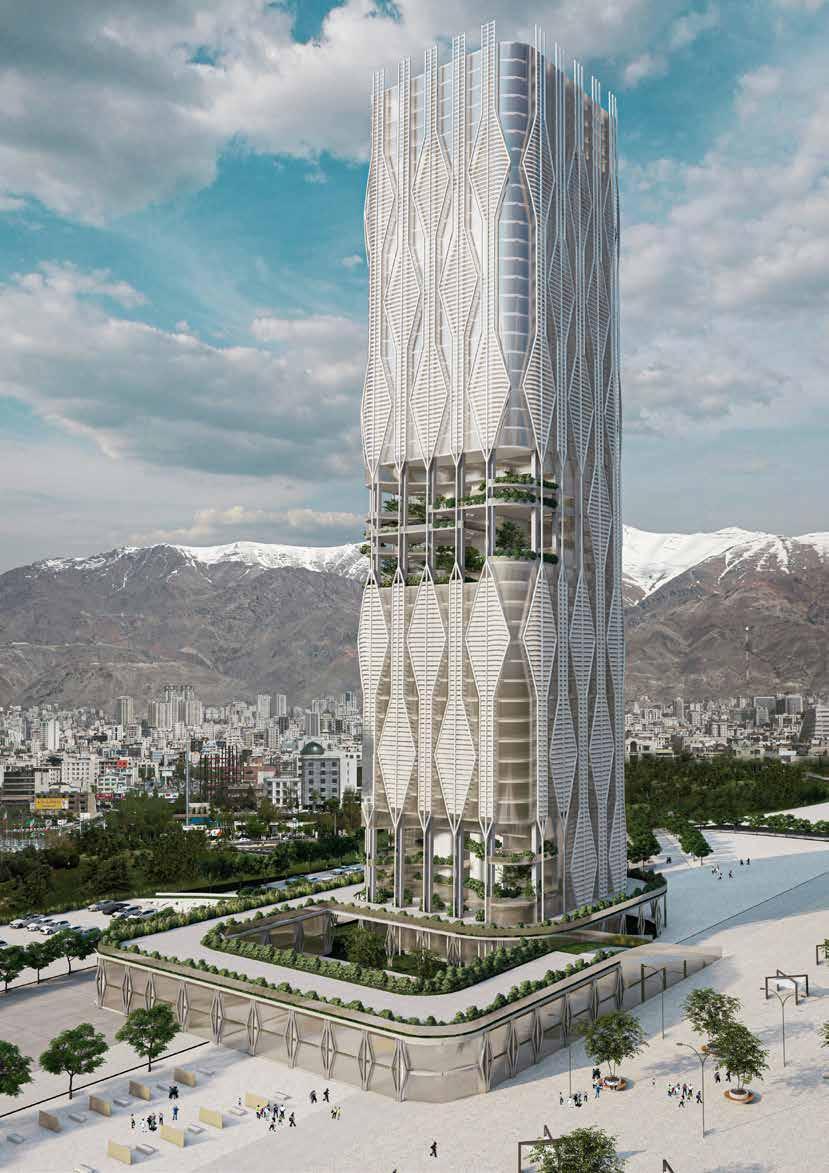
Tehran skyscraper is located in a strategic site in Tehran, capital of Iran. The building is at the crossroads between a view to the beautiful Alborz mountains in the North and the ancient historical part of the city in the South. Both cultural and residential areas surround the site. The considerations for design starts at the urban scale. Studying and analyzing the context of the location. A rich and diverse background of cultural heritage deserves to be treated as a source of inspiration in our work. The site design is developed as connection between the cultural and civic areas that surround it. The site is also designed to take advantage of the natural topography of the land. The architectural design of the Tehran skyscraper has two main factors. Visual connectivity and functional connectivity. The visual aspect is to provide a link with the mountain and with the historical parts of Tehran, and the functional aspect is to become a physical infrastructure link to other cultural buildings in the city. At the same time, some basic aspects of Iranian architecture like central courtyard and shading system has been considered in the design process. We envision the tall building as a center that promotes the values of connection. The building facilitates the connection and interaction of ideas and art through our design choices.
CHAPTER 1 THEORY AND METHODOLOGY
The GENERATION HUB consists of exhibition halls, small amphitheaters, Persian cultural center, library, offices, and hotel.
The GENERATION HUB acts as a think tank. This building with the various parts it brings together, will be a productive spot. Young people can cooperate in different ways in various spaces of this building and implement their new ideas in the field of culture, society, tourism, etc. We believe that if the necessary facilities and platform are provided for the new generation, they can well help increase cultural and social exchanges and improve economic conditions.
The most important part is the spaces for NGO and SRARTUPs which allows people to be there from idea to implementation and plays the key roll in this productive spot. This building can host the NGOs about environment, knowledge sharing, cultural heritage, etc and the fashion, healthcare, food, technology, travel, etc STARTUPs. The most especial STARTUP can be TOURISM STARTUPS FOCUS ON INNOVATION AND SUSTAINABILITY under supervision the UNWTO which can help increase communications and make Iran a tourism hub.
GENERATION HUB: Tehran is the capital of Iran since 1786 and it’s the first destination of visitors coming to Iran. There are 289 national monuments in Tehran and one of the 26 UNESCO world heritage in Iran is located in Tehran. According to UNWTO (world tourism organization), 7.295.000 person visited Iran in 2018 and this number was 9.107.000 in 2019. According to Iran’s cultural, historical, and natural heritage, increasing the communications in this fields can help the Economic situation of Iran. Until 2019, about 22% of Iran’s population is young generation between 15 - 22 years old. This points led us to design the GENERATION HUB. A center to gather people, especially the younger generation who have fresh ideas but may not have enough facilities to implement their ideas.
10 1.1: THEME
11 HIGH NUMBER OF CULTURAL & HISTORICAL HERITAGE LOW TOURISM RATE LACK OF FACILITIES HIGH NUMBER OF YOUNG GENERATION THE GENERATION HUB


Climate changes and depletion of natural resources are two of the world challenges which are results of Industrialization and Unsustainable population growth. Ken Yeang explains that building vertically instead of expanding a city horizontally is a more sustainable way to build and reduce the impact of the buildings on the natural environment (Yeang K.1994).
BIOCLIMATIC SKYSCRAPER:
12 1.1: THEME
Guiding principles for designing tall buildings are: Simplicity, Structural clarity, and Sustainability which Leads to design towers that can impact climate change and reduce demands on Simplicityresources. means Purity of concept. It includes a structural engineering response that is sympathetic to architectural goals. Structural clarity means defining a system with clear load paths and Creating certainty in environments with potentially very uncertain events. Sustainability means design and construct tall buildings to be self-sufficient.
According to Yeang, there are three methodologies in the development of the bioclimatic skyscraper: Climatic: buildings should be designed to optimize the ambient conditions and new building forms that are specific to their locations. Cultural: architecture needs to respond to the local conditions of Desirelife. of join the ‘developed’ world: requiring a change from traditional low-rise structures to a modern high-rise strategy (Yeang InK.1994).design process of the Tehran skyscraper we tried to consider all the key words mentioned above besides, we tried to keep the coexistence of local identities and global identities and the interaction between building and nature by having vertical landscaping, building solar sky courts, transitional spaces and so on.
13 Culture Developed worldClimate


14 1.2: PLACE
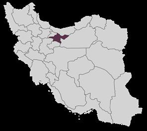
CITY OF TEHRAN: Tehran, also spelled Teheran, the capital city of Iran and the center of the province of Tehran, located in north-central Iran at the foot of the Alborz mountain range. Tehran has grown from a small city to a major metropolis: situated in an urban region of 14 million inhabitants, Tehran is Iran’s largest city and one of the most populous cities of the world. Area city, 270 square miles (707 square km). Pop. (2016) city, 8,693,706. Tehran is the most populous city in Iran and Western Asia, and has the secondlargest metropolitan area in the Middle East (after Cairo). It is ranked 24th in the world by the population of its metropolitan Thearea.metropolis of Tehran is divided into 22 municipal districts, each with its own administrative center. 20 of the 22 municipal districts are located in Tehran County’s Central District, while the districts 1 and 20 are respectively located in the counties of Shemiranat and Ray. Although administratively separate, the cities of Ray and Shemiran are often considered part of Greater TehranTehran.is the economic center of Iran. Despite numerous attempts to diversify the country’s economy, it is dominated by the oil industry, controlled from Tehran by the national government.
15 POPULATION8.693million (2016) 707AREA PROVINCIALkm2 CENTERPOPULATIONTehran82.91million (2019) 1,648,195AREA km2 PROVINCE31 • IRAN • Tehran Province

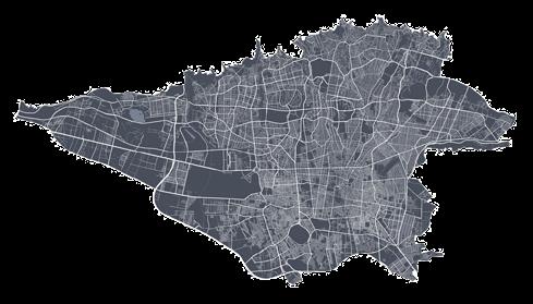


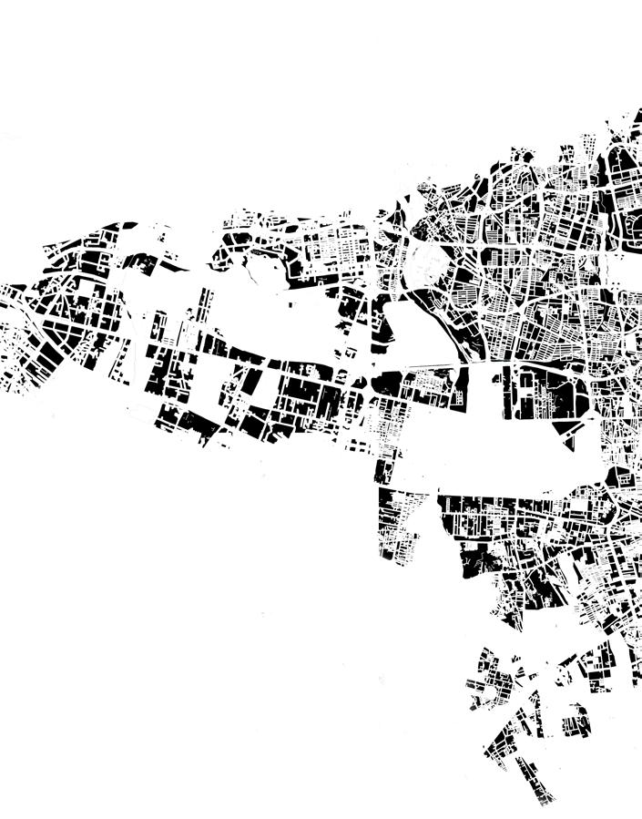
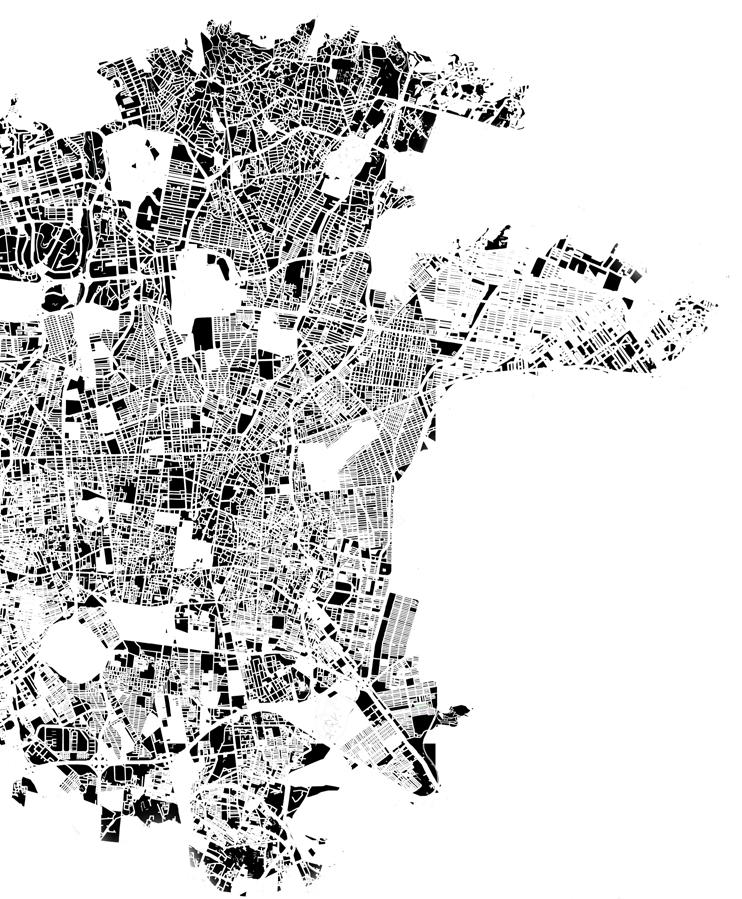
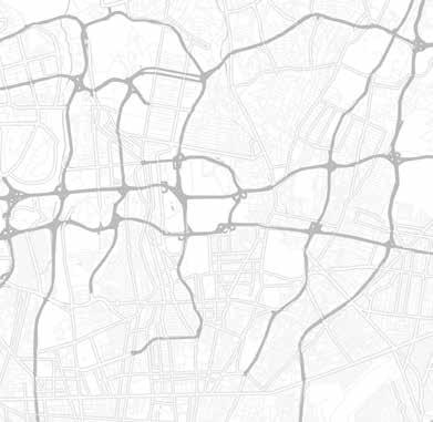
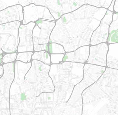
16 1.2: PLACE BUILT MASS PLAN OF TEHRAN
17
18 1.2: PLACE
CONTEXT Modernization was an important period in Iranian history that began with the Russo-Persian wars (1804-13) and lasted until the end of the Pahlavi dynasty (1925-79). These turbulent decades spurred a series of social and cultural transformations which resulted in the emergence of modern Iran. The need for modernization and the improvement of Iran‘s defense capabilities became evident with the increase in exchanges between Iran and the West which started in the Qajar period (1789-1925).
After the Second World War, between 1945 and 1953, Iran underwent major socio-urban changes. During this period, an urban middle class quickly formed, technocratic parties were developed, and modern urban planning began. Due to the high rate of population growth, the country was faced with a severe housing shortage (Bani Masoud,2020).
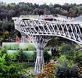
19 Tabiat Bridge Tehran book garden Ab o Atash MusallaParkMilad Tower Pardisan Park


20 1.3: ROLE
The first tall building in Tehran was Shams-ol-Emareh (Edifice of the Sun) in Golestan palace built in 1867. This building was the tallest one in Tehran till 1951. Construction of tall buildings based on the modern meaning began in Iran in 1951. Nowadays Tehran has the most high-rise buildings in Iran and its population density is the highest in the country. The tallest tower in Tehran and Iran is Milad tower which is a multi-purpose tower. It is the sixth-tallest tower and the 24th-tallest freestanding structure in the world.
Driving forces of constructing tall buildings including: Population Increase, Rural-to-Urban Migration, Demographic Change, Agglomeration, and Human Aspiration. Tall Buildings persist in the 21st century due to Strong commitment to urban sustainability and Significant population increase.
TALL BUILDING IN TEHRAN:
21 Socio-Economic power Showcase for Building Technology Architecture and the City Tourist Attraction Identity for Capital Sustainability toward Climate Financial Impact Showcase of Green Skyscraper


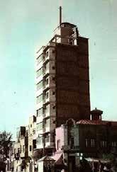
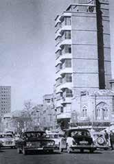
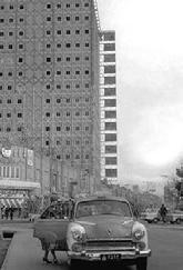
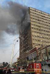
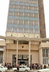
22 1.3: ROLE CONTEMPORARY TALL BUILDINGS IN TEHRAN: Name: The first tower in Tehran/ Khanshaghaghi building Location: Jomhouri st., After Saadi metro station, Tehran Engineer and designer: Houshang Khanshaghaghi Date: 1949 - 1951 Type: Residential Number of Floors: 10 Floors (40m) Name: Plasco Building Location: Jomhouri st., After Saadi metro station, Tehran Date: 1960 - 1963 Type: Residential and Commercial building Number of Floors: 14 Floors (42m)


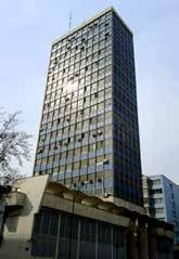
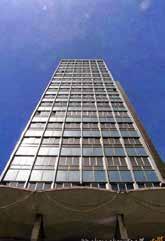
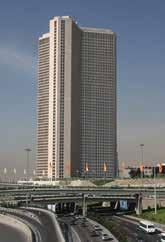
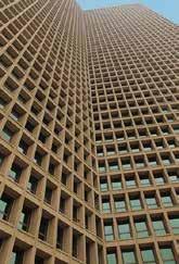
23 Name: Tehran Stock Exchange Location: Hafez st., Tehran Date: 1963 - 1969 Type: office Building Number of Floors: 19 Floors (68m) Name: Tehran International Tower Location: north of Yusef Abad and Amir Abad districts, Kordestan and Resalat Expy,Tehran/ Date: 2005 Type: Residential Number of Floors: 56 Floors (162m)


The metropolis of Tehran is divided into 22 municipal districts, each with its own administrative center. We tried to analyze the Districts 3(up), 6 (down left), and 7 (down right) as our site is at the middle of these 3 districts and has direct connection with them.
24 1.4: MORPHOLOGY URBAN TEXTURE: Schools Medical Cultural Sport Complex
Residential texture: Public functions:
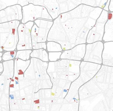
The slope of the region is from north to south and a number of important tourist attractions and cultural centers of Tehran are located in these districts.
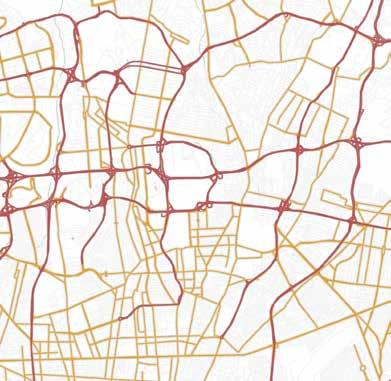
25 Highway Arterial Connections:Parks:
CHAPTER 2 SITE AND CONTEXT
28 2.1: SITE INTRODUCTION
ABBAS ABAD DISTRICT:
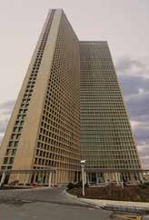
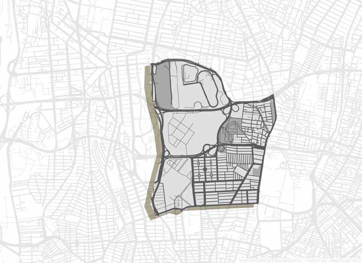
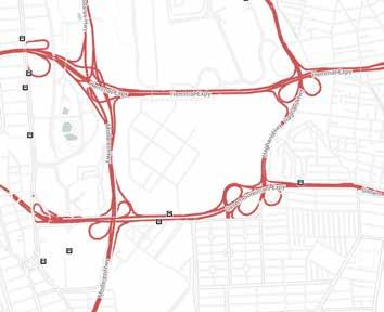
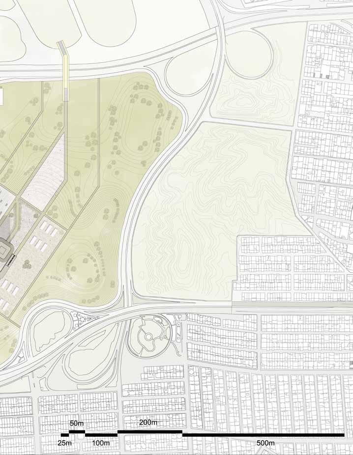
The significance of Abbasabad, the site of the project, stemmed from its geographic location and peculiar topography; with the northward expansion of Tehran, the site had gained relative centrality amid the expanding urban fabric between Tehran’s old core and Shemiran. Indeed, on the Tehran plain, which slopes from north to south, the Abbasabad hills are the most prominent natural outcrop; from their highest point one could view not only the old city and the mountains but also Damavand mountain, Iran’s highest peak, and the desert to the south. Thanks to its topography of deep valleys and steep ridges, the site survived the rapid urbanization of north Tehran. From the early 1960s onwards, Abbasabad, frozen amid a dense fabric of apartment buildings, was considered an exceptional site for a new civic center in the Abbascapital.Abad was originally conceived in the 1950s and 60’s as a housing and residential center for members of various branches of the military. Later on, the district grew and its boundaries blended with other expanding nearby neighborhoods and the district’s city planning grid was modern and geometric with perpendicular wide Byavenues.theearly 70’s, the district was experiencing exceptional growth, partly due to its location and the availability of land on still-barren Abbas Abad Hills, which eventually became the site for the nevermaterialized mega project of Shahestan Pahlavi.
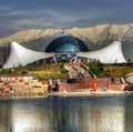
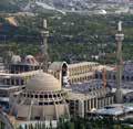
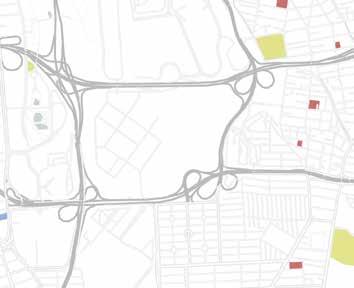
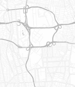
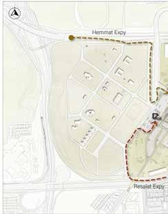
29 National Library of Iran Tehran Book Garden Imam Khomeini Musalla Islamic Revolution & Holy DefenseHonarMuseumGarden Academy of Persian Language & Literature Tabiat Bridge Islamic Culture and Communication Organization Behesht Madaran Park Eram Grand Hotel Academy of Science Taleghani Forest Park Sadra Islamic Philosophy Foundation Shahid Hemmat Metro Station


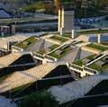
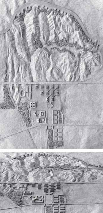
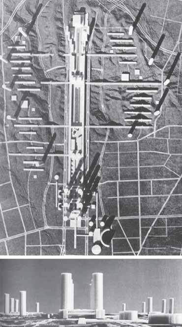
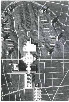
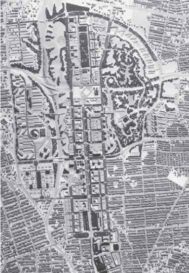
A rectangular colonnaded plaza, oriented towards the north, leads to an oval forecourt, which precedes a triangular area covered with blocks of various functions arranged in a checkerboard pattern.25 In Kahn’s proposal, the hills were preserved as a natural park and the triangular area, the core of the complex, took its form from the land’s natural contours. In giving the plan a northward direction, Kahn may have considered the backdrop of the Alborz Tange’sMountains.concept consisted of an enormous linear mega structure, featuring cylindrical towers at its beginning and running the site’s entire north–south width; a number of other high-rise cylindrical towers and bridge-type residential buildings covered the surrounding landscape.
ABBAS ABAD DISTRICT (SHAHESTAN PAHLAVI):
30 2.1: SITE INTRODUCTION
In 1971, Shah ordered the Tehran Municipality to assume responsibility for building a national center in Abbasabad. In 1973, a development corporation called ‘Sherkat Sahami Nosazi Shahestan Pahlavi’ (Corporation for the Development of Shahestan Pahlavi) was established by the Municipality to manage the planning and construction of the site. In October 1973, the American architect Louis Kahn was commissioned by Queen Farah to prepare a proposal for Abbasabad in collaboration with the Japanese architect Kenzo Tange. The Queen gave each architect a separate audience, and then asked them to collaborate. the two architects worked independently but then they agreed to proceed on the basis of Kahn’s sketch plan.
31 Kahn’s proposal for Abbasabad Louis I. Kahn Collection, University of Pennsylvania and the Pennsylvania Historical and Museum Commission Tange’s proposal for Abbasabad Kenzo Tange, ‘Abbasabad New City Center’, The Japan Architect 51.8-9 (1976): 105.
Tange agreed to proceed on the basis of a sketch plan that Kahn had made in Tehran. According to Tange, the architects also agreed on five major points: to preserve the site’s ‘beautiful topography’; ‘to express clearly in the structure the nature of district as a new urban center at the junction point of the north–south and east–west axes of Tehran’; ‘to create a central plaza to be a cultural center symbolizing the 2500 years of Iranian history’; ‘to give the central plaza a classical mood like that of Isfahan and to create an urban center silhouette recalling that of Persepolis.
* This project was stopped due to the revolution.
32 2.1: SITE INTRODUCTION
Following the unexpected loss of Kahn, a modified synthetic scheme was drawn up at the Tange office (URTEC), supposedly based on their agreements. In it, Kahn’s diamond-shaped civic center was preserved, but Tange’s towers, though truncated, were still overwhelmingly dominant.
In late 1974, the preliminary concept of LDI presented their proposal to Shah. A master plan for 554 hectares of open land, with more than five million meters of floor space, was prepared with ‘a sense of urgency’ over an eighteen month period. The overall scheme of Shahestan, is characterized by rectilinear geometry, axial configuration and massive forms. The main commercial and governmental buildings are arranged in a north–south ‘linear spine’, which recalls Tange’s proposal. A tree-lined boulevard with neo-classical overtones constitutes the main urban artery of the complex, and is in fact the only major addition of the LDI plan to the conceptions developed in earlier proposals. The boulevard leads to Shah and Nation Square, which was to be ‘the focus of Tehran’s political, social, cultural, ceremonial and commercial activities. The physical form of the arcaded plaza is inspired by Isfahan’s Safavid maydan, and is larger in size than Moscow’s Red Square.
ABBAS ABAD DISTRICT (SHAHESTAN PAHLAVI):
33 Tange’s proposal after Kahn’s death Kenzo Tange, ‘Abbasabad New City Center’, The Japan Architect 51.8-9 (1976) LDI ‘s proposal for Abbasabad Llewelyn-Davies International, Shahestan (1976), 2:2.
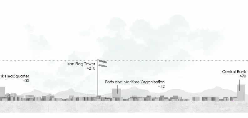
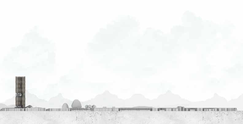
34 2.2: URBAN SECTION
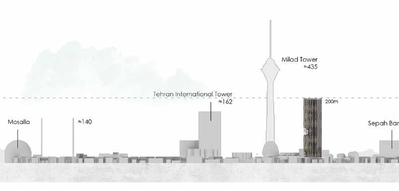
35
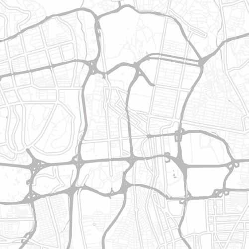
36 2.3: SITE ANALYSIS RESIDENTIAL AREA TEXTURE: PARKS: PUBLIC FUNCTION TEXTURE: CONNECTIONS: Merto Station Bus Stop Highway Schools Medical Cultural Sport Complex
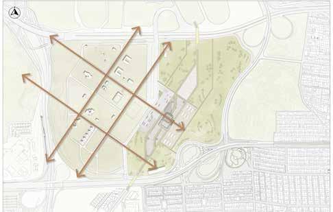
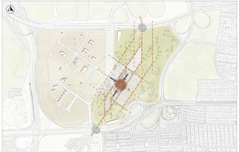
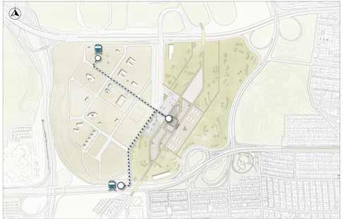
Position and Orientation of the Tower location: Intersection of two main axis strong axis extracted from surrounding area with climatic consideration
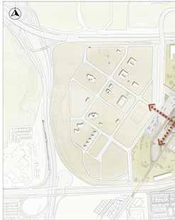
bridges Plus car access from Hemmat Expy
Nowrooz Park Ab o Atash
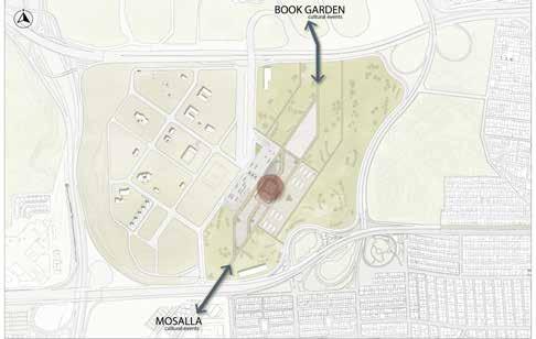
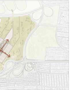
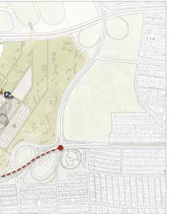
Creating a connection between the North and south part of Abbas Abad as the north area of Abbas Abad hills are dedicated to several cultural cen ters and communities. Our project area can create a connection path between these two part of the hills. PedestrianSolution?
Two main Pedestrian bridges present at the district of Abbas Abad Tabiat Bridge: The 270-metre (890 ft) bridge connects two public parks — Taleghani Park and Abo-Atash Park — by spanning Modar res AbrishamExpresswayBridge (silk bridge) : It bridges the urban highway Hemmat Expressway, and connects the parks Ab-o-Atash and Nowruz.
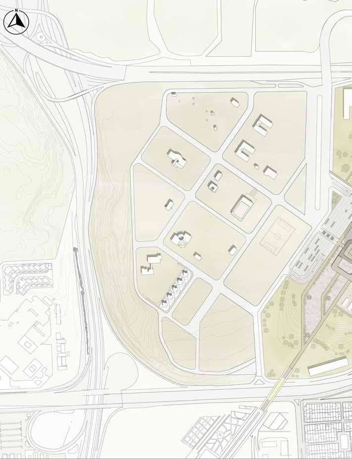
37 DEFINING PROJECT AREA:
ParkTaleghani
CHAPTER 3 ARCHITECTURAL DESIGN
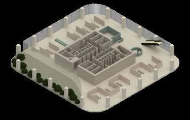
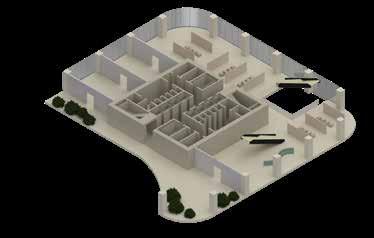
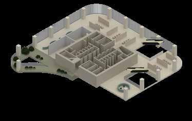
40 3.1: MASTER PLAN
41
42 Connecting pedesterian bridges Placement and orientation of buildingExisting grid extracted from adjacent area 3.1: MASTER PLAN Main car access from adjacent
43 building Main axis and accesses to building highways to site Metro stations and pedesterian access to site
44 3.2: PROGRAM
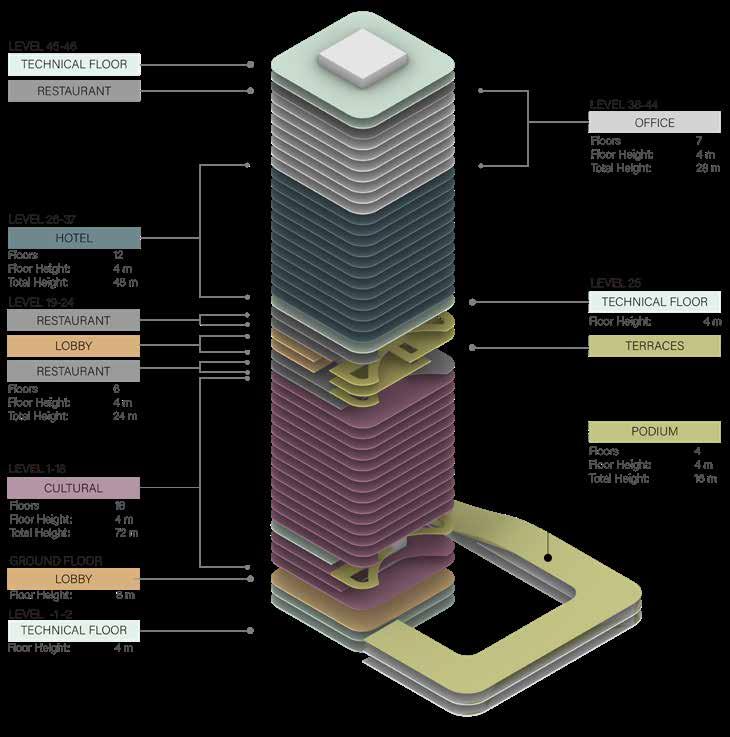
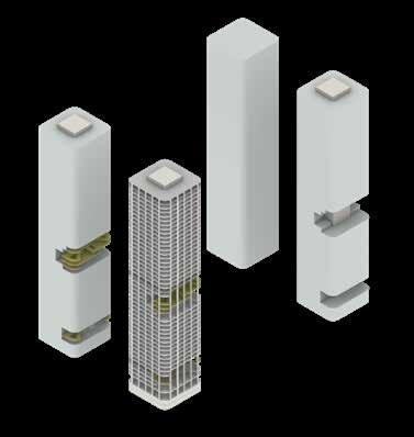
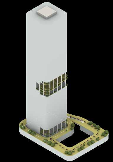
45 Cuts looking to the south Adding toContinuityPODIUMgreeneryfromgroundterraces Levelsstructureand TerracesAdding

3.3: SECTIONS AND ELEVATIONS
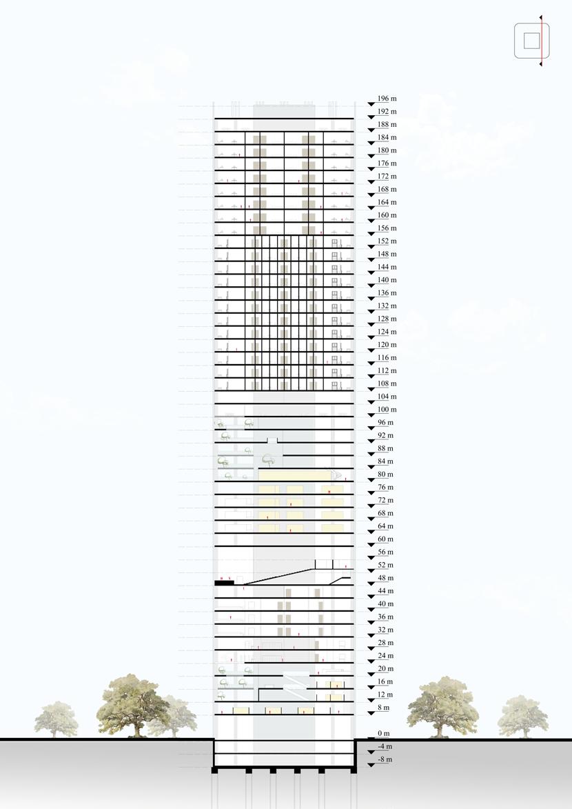

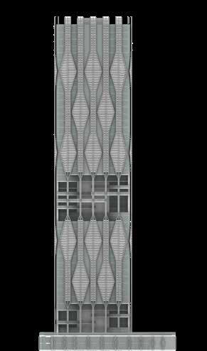
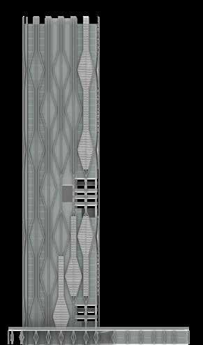
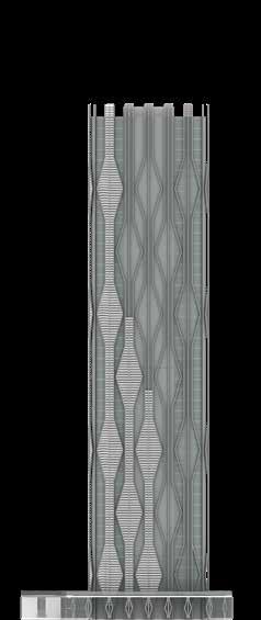
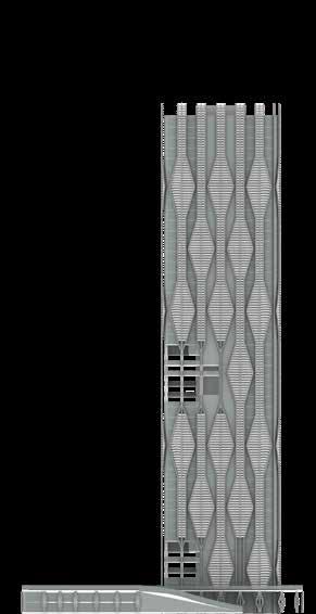
48 3.3: SECTIONS AND ELEVATIONS NORTH SOUTH EAST WEST
EAST ELEVATION SOUTH ELEVATIONNORTH ELEVATION WEST ELEVATION
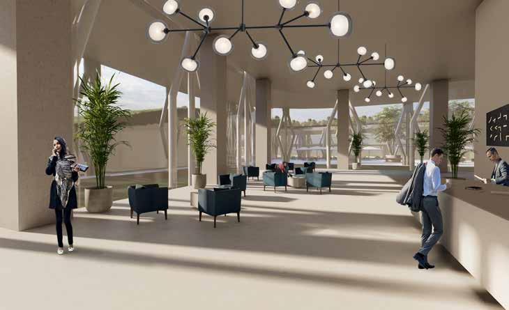
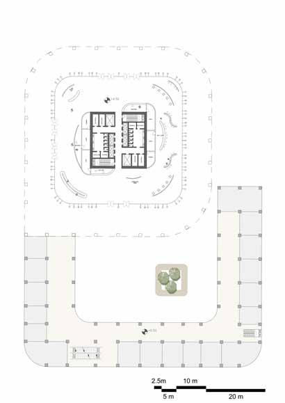
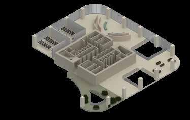
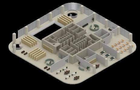
3.4: ARCHITECTURAL PLANS GROUND FLOOR LOBY

51 FIRST FLOOR TERRACES
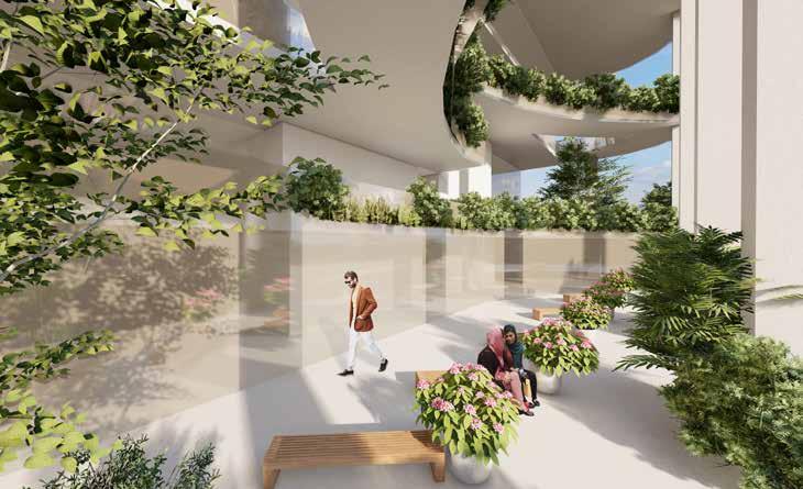
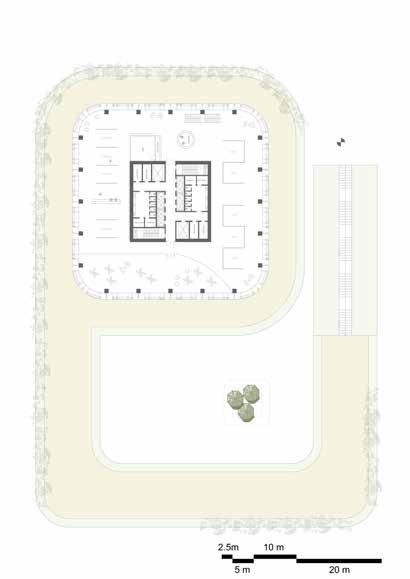
PODIUM ROOF WITH CONNECTION TO BUILDING GREEN AREA PODIUM 3.4: ARCHITECTURAL PLANS
53 GALLERY LEVEL 1 LEVEL 2 2m 10m5m 6.00 7.50 7.50 7.50 7.50 6.00 6.00 7.50 7.50 7.50 7.50 6.00 7.507.507.506.00 7.507.507.50 42.00 42.00 42.00 1 2 3 4 5 6 7 5 DEFGCBA GCBAFED6.00 2m 10m5m 6.00 7.50 7.50 7.50 7.50 6.00 6.00 7.50 7.50 7.50 7.50 6.00 6.007.507.507.507.506.00 6.007.507.507.507.50 42.00 42.00 42.00 1 2 3 4 5 6 7 DFGCBA GCBAFD6.00


54 LEVEL 3 LEVEL 4 +16.00 2m 10m5m 6.00 7.50 7.50 7.50 7.50 6.00 6.00 7.50 7.50 7.50 7.50 6.00 6.007.507.507.507.506.00 6.007.507.507.507.50 42.00 42.00 42.00 1 2 3 4 5 6 7 DFGCBA GCBAFD6.00 +16.00 2m 10m5m 6.00 7.50 7.50 7.50 7.50 6.00 6.00 7.50 7.50 7.50 7.50 6.00 6.007.507.507.507.506.00 6.007.507.507.507.50 42.00 42.00 42.00 1 2 3 4 5 6 7 DFGCBA GCBAFD6.00 3.4: ARCHITECTURAL PLANS

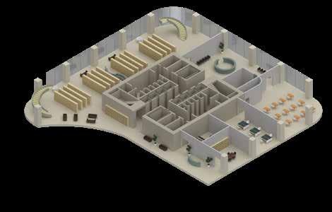
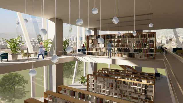
55 LIBRARY LEVEL 5 2m 10m5m 6.00 7.50 7.50 7.50 7.50 6.00 6.00 7.50 7.50 7.50 7.50 6.00 7.507.507.506.00 7.507.507.50 42.00 42.00 42.00 1 2 3 4 5 6 DFGCBA GCBAFD6.00
56 LEVEL 6 2m 10m5m 6.00 7.50 7.50 7.50 7.50 6.00 6.00 7.50 7.50 7.50 7.50 6.00 6.007.507.507.50 6.007.507.507.5042.0042.0042.00 42.00 1 2 3 4 5 6 7 1 2 3 4 5 6 7 EFGCBA GCBAFE 3.4: ARCHITECTURAL PLANS
57 LEVEL 7-8-9 LEVEL 10 LEVEL 11 LEVEL 17 +34.00 +33.20+33.20 2m 10m5m 6.00 6.00 7.50 7.50 7.50 7.50 6.00 6.00 7.50 7.50 7.50 7.50 6.00 7.507.507.506.00 7.507.507.5042.0042.0042.00 42.00 1 2 3 4 5 6 7 1 2 3 4 5 6 EFGCBA GCBAFE 2m 10m5m 6.00 6.00 7.50 7.50 7.50 7.50 6.00 6.00 7.50 7.50 7.50 7.50 6.00 7.507.507.506.00 7.507.507.5042.0042.0042.00 42.00 1 2 3 4 5 6 7 1 2 3 4 5 6 EFGCBA GCBAFE +48.00 +49.20 +49.20 6.00 6.00 7.50 7.50 7.50 7.50 6.00 6.007.507.507.507.506.00 6.007.507.507.507.5042.0042.0042.00 42.00 1 2 3 4 5 6 7 1 2 3 4 5 6 7 DEC DCE +80.00 6.00 6.00 7.50 7.50 7.50 7.50 6.00 6.007.507.507.507.506.00 6.007.507.507.507.5042.0042.0042.00 42.00 1 2 3 4 5 6 7 1 2 3 4 5 6 7 DEC DCE
58 NGO / START UP LEVEL 12-15 2m 10m5m 6.00 6.00 7.50 7.50 7.50 7.50 6.00 6.00 7.50 7.50 7.50 7.50 6.00 6.007.507.507.507.506.00 6.007.507.507.507.50 42.00 42.00 42.00 1 2 3 4 5 6 7 DFGCBA GCBAFD 3.4: ARCHITECTURAL PLANS

59 LEVEL 16 NGO / START UP 2m 10m5m 6.00 7.50 7.50 7.50 7.50 6.00 6.00 7.50 7.50 7.50 7.50 6.00 7.507.507.50 7.507.507.5042.0042.00 1 2 3 4 5 6 7 1 2 3 4 5 6 7 EFGCBA GCBAFE

60 LEVEL 18 LEVEL 19 LEVEL 20 LEVEL 21 +88.00 +74.00 6.006.007.507.507.506.00 6.007.507.507.5042.0042.0042.00 42.00 1 2 3 4 5 6 7 1 2 3 4 5 6 7 DEGC GCED +92.00 +74.00 +74.00 6.006.007.507.507.506.00 6.007.507.507.5042.0042.0042.00 42.00 1 2 3 4 5 6 7 1 2 3 4 5 6 7 DEGC GCED +94.00 +74.00 +92.00 2m 10m5m 6.00 6.00 7.50 7.50 7.50 7.50 6.00 6.00 7.50 7.50 7.50 7.50 6.00 6.007.507.507.506.00 6.007.507.507.5042.0042.0042.00 42.00 3 5 6 1 2 3 4 5 6 7 DEFGCBA GCBAFED +98.00 +92.00 2m 10m5m 6.00 6.00 7.50 7.50 7.50 7.50 6.00 6.00 7.50 7.50 7.50 7.50 6.00 7.507.507.506.006.00 6.007.507.507.5042.0042.0042.00 42.00 3 5 6 1 2 3 4 5 6 7 DEFGCBA GCBAFED 3.4: ARCHITECTURAL PLANS


61 LEVEL 24-35 +110.00 2m 10m5m 6.00 6.00 7.50 7.50 7.50 7.50 6.00 6.00 7.50 7.50 7.50 7.50 6.00 7.507.507.506.00 7.507.507.50 42.00 42.00 42.00 1 2 3 4 5 6 7 DFGCBA GCBAFD
62 LEVEL 45 LEVEL 22 LEVEL 23 LEVEL 36-44 +92.00 2m 10m5m 6.00 6.00 7.50 7.50 7.50 7.50 6.00 6.00 7.50 7.50 7.50 7.50 6.00 7.507.507.507.506.006.00 6.007.507.507.507.5042.0042.0042.00 42.00 1 2 3 4 5 6 7 DFGCBA GCBAFD MEP+106.00 2m 10m5m 6.00 6.00 7.50 7.50 7.50 7.50 6.00 6.00 7.50 7.50 7.50 7.50 6.00 6.007.507.507.507.506.00 6.007.507.507.507.50 42.00 42.00 42.00 1 2 3 4 5 6 7 DFGCBA GCBAFD 2m 10m5m 6.00 6.00 7.50 7.50 7.50 7.50 6.00 6.00 7.50 7.50 7.50 7.50 6.00 7.507.507.506.00 7.507.507.50 42.00 42.00 42.00 1 2 3 4 5 6 7 DFGCBA GCBAFD 2m 10m5m 6.00 6.00 7.50 7.50 7.50 7.50 6.00 6.00 7.50 7.50 7.50 7.50 6.00 7.507.507.506.00 7.507.507.50 42.00 42.00 42.00 1 2 3 4 5 6 7 DFGCBA GCBAFD 3.4: ARCHITECTURAL PLANS
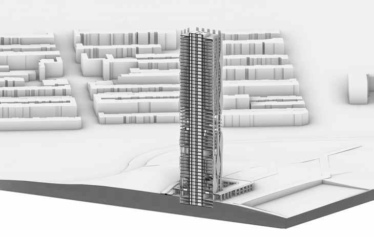
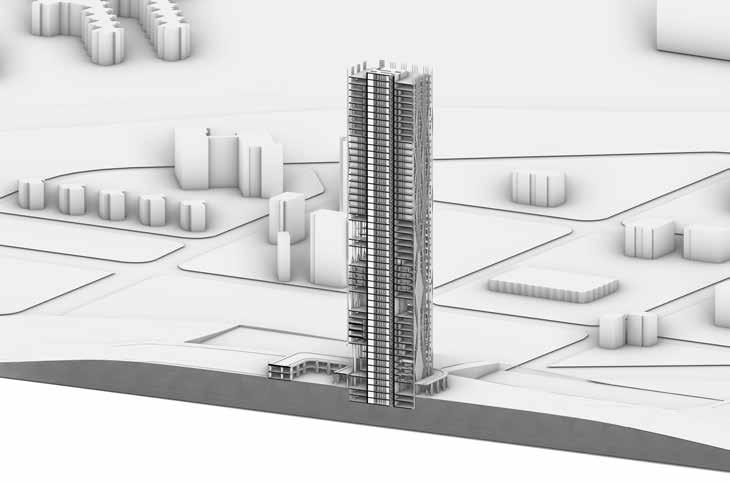
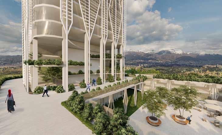
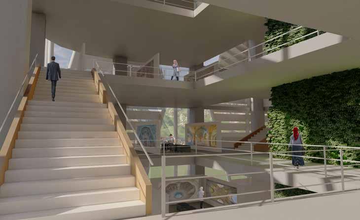
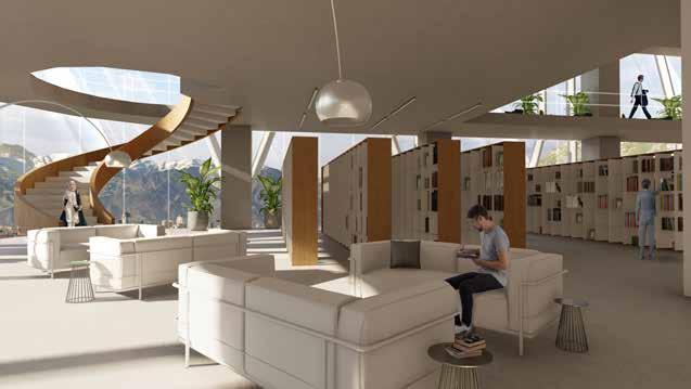
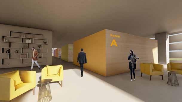
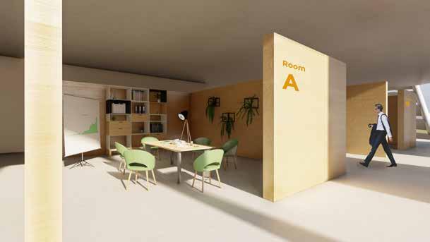
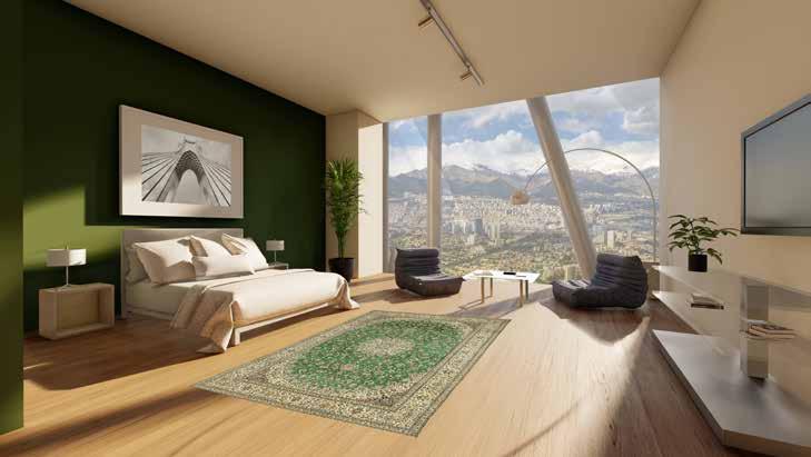
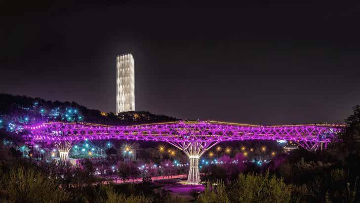
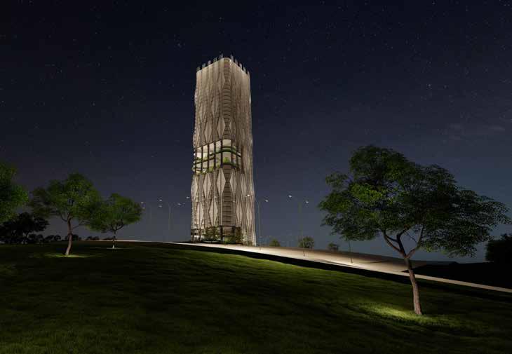
63 3.5: RENDERINGS

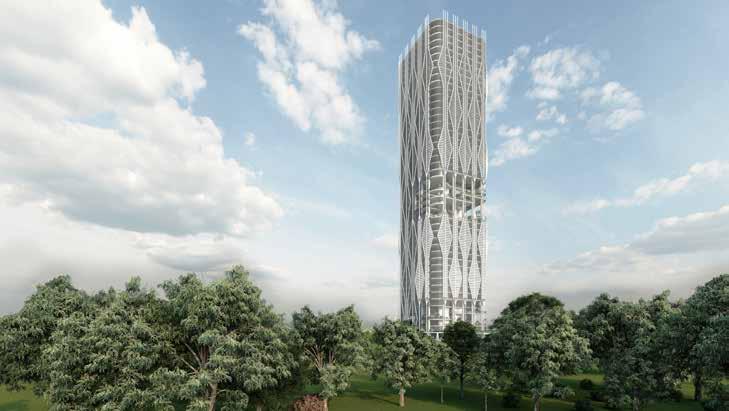
64 3.5: RENDERINGS

65
CHAPTER 4 TECHNICAL DESIGN
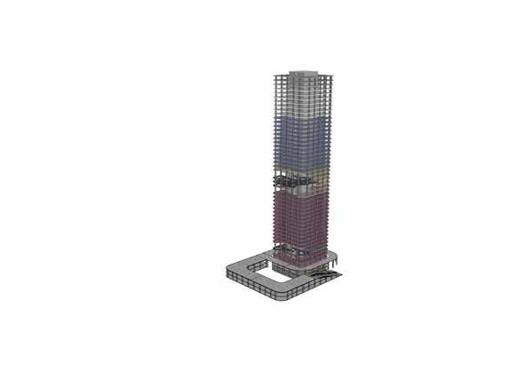
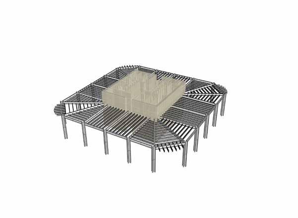
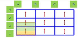
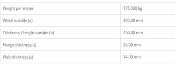
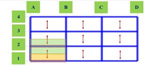
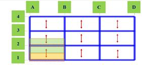
68 4.1: STRUCTURAL DESIGN Core and columns VENTILATION VENTILATIONPLUMPING7,5 43 43 6,56,57,57,57,5 6,5 7,5 7,5 7,5 1 2 3 4 5 FEDBACG primary secondarybeambeam, placed every 1 m primary beam • 3D Structural Hierarchy


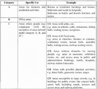
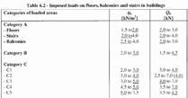
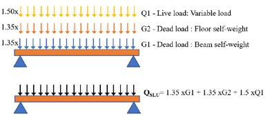
69 DEAD LOAD AND LIVE LOAD IN TYPICAL FLOOR SLAB: According to Eurocode 1 EN 1991-1-1 ComFlor 210 PLUMPINGVENTILATION FIRE-SMOKE PLUMPING 43 6,5 7,5 7,5 7,5 7,5 6,5 1 2 3 4 5 6 7 KEY-LOCK ceiling system Dead load of the floor = 4.80 KN/M 2 A - Bedrooms in hotels B - Office areas C1 - Areas with tables C2 - Areas with fixed seats C3 - Areas without obstacles for moving peaple C4 - Areas with possible physical activities Distr. Load = 2 KN/M 2 Distr. Load = 3 KN/M 2 Distr. Load = 3 KN/M 2 Distr. Load = 4 KN/M 2 Distr. Load = 5 KN/M 2 Distr. Load = 5 KN/M 2 We can consider 5 KN/M2 as the default live load of the Building. TOTAL FLOOR LOAD = 4.80 KN/M 2 + 5 KN/M 2 = 9.80 KN/M 2 MATERIAL THICKNESS(M) MATERIAL(KN/M³)DENSITY WEITGH(KN/M²) Waterproof layer 0.02 10 0.2 Screed 0.05 2.5 0.125 Separation layer 0.005 0.0015 0.00001 Insulation 0.08 0. 2 0.016 Reinforced concrete & Composite metal sheet ComFlor 210 0.29 25 2.79 Suspended ceiling system KEY LOCK 0.02 10 0.2 “Partition wall” loads 1 0.8 0.8 Suspended plates 0.50 TOTAL 4.63 Dead load of the Roof = 4.63 KN/M2 Live load of the Roof = 5 KN/M2 TOTAL FLOOR LOAD = 4.63 KN/M 2 + 5 KN/M 2 = 9.63 KN/M 2 MATERIAL THICKNESS(M) MATERIAL(KN/M³)DENSITY WEITGH(KN/M²) Polished stone 0.015 0.36 Screed 0.05 2.5 0.125 Separation layer 0.005 0.0015 0.00001 Insulation 0.08 0. 2 0.016 Reinforced concrete & Composite metal sheet ComFlor 210 0.29 25 2.79 Suspended ceiling system KEY LOCK 0.02 10 0.2 “Partition wall” loads 1 0.8 0.8 Suspended plates 0.50 TOTAL 4.80

70 SECONDARY BEAM ANALYSIS: VENTILATIONELECTRICAL PLUMPING VENTILATION VENTILATION ELECTRICAL FIRE-SMOKE PLUMPING VENTILATION 7,5 43 6,56,57,5FDBCG Area of the slab on the beam = 1 m × 11 m = 11 m 2 HEB 400 ULS : SLS : Calculations for the course Architectural Design Studio for Complex Modules Structure Prof. Luca D'Alessandro, Grigor Angjeliu Academic Year 2019-2020 In the grey cells the numbers can be hard typed. In other cells there are *******************************************************************************************************************************already Part 2: Beam Total Load Calculation Influence area width I 1.0 m Linear load G1 1.6 kN/m Dead load: Beam self weight Area load G2 4.8 kN/m2 Linear load G2 4.8 kN/m Dead load: Floor Self weight Area load Q1 5.0 kN/m2 Linear load Q1 5.0 kN/m Live load: Residential Linear load G1 1.6 kN/m Dead load: Beam self weight Linear load G2 4.8 kN/m Dead load: Floor Self weight Linear load Q1 5.0 kN/m Live load: Residential Coefficient for G1 1 Coefficient for G2 1 Coefficient for Q1 1.0 TOTAL BEAM LOAD Quls 11.4 kN/m Calculations for the course Architectural Design Studio for Complex Modules Structure Prof. Luca D'Alessandro, Grigor Angjeliu Academic Year 2019-2020 In the grey cells the numbers can be hard typed. In other cells there are already *******************************************************************************************************************************formulas. Part 2: Beam Total Load Calculation Influence area width I 1.0 m Dead load: Beam self weight Linear load G2 4.8 kN/m Dead load: Floor Self weight 5.0 kN/m2 5.0 kN/m Live load: Residential Linear load G1 1.6 kN/m Dead load: Beam self weight Linear load G2 4.8 kN/m Dead load: Floor Self weight Linear load Q1 5.0 kN/m Live load: Residential Coefficient for G1 1.3 Coefficient for G2 1.3 Coefficient for Q1 1.5 TOTAL BEAM LOAD Quls 15.8 kN/m 15.8 KN/m 11 m 243.5126.60 88.55 Calculations for the course Architectural Design Studio for Complex Constructions 1 Modules Structure Prof. Luca D'Alessandro, Grigor Angjeliu Academic Year 2019-2020 In the grey cells the numbers can be hard typed. In other cells there are already *******************************************************************************************************************************formulas.******************************************************* 1. Calculate M_ED External Bending Moment Calculation Beam Lenght L 11 m Linear load on beam Q_ULS 15.8 kN/m M_ED 239.0 kNm 238975000.00 Nmm 2. Choose steel class Steel class S… 355 3. Calculate fyd from the steel class fyk 355 MPa γs 1.15 fyd 309 MPa 4. Calculate Wpl Wpl 774144.4 mm3 774 10^3 mm3 5. Choose the cross section such as it has a Wpl greater than the one calculated Beam chosen HEB 400 Wpl chosen 3232 10^3 mm3 OK 2. Calculate shear force Beam Lenght L 11 m Linear load on beam Q_ULS 15.8 kN/m Shear force 86.9 kNm 86900000.00 Nmm 2. Choose steel class Steel class S… 355 3. Calculate fyd from the steel class fyk 355 MPa γs 1.15 fyd 309 MPa 4. Calculate Avy Avy 281507 mm2 282 10^2 mm2 5. Choose the cross section such as it has a Wpl greater than the one calculatedAvy greater than the one calculated Beam chosen HEB 400 Avy chosen 6998 10^2 mm2 OK 3. Deformation Beam Lenght L 11 m Linear load on beam Q_SLS 11.4 kN/m E 200 Gpa 200000000 KN/m2 Ix 57680 cm4 0.0005768 m4 ∆ Total (= (5/384)*((Q_SLS*L^4)/EI)) 0.018839055 m 18.839055 mm ∆ Max L/250 4.4 cm 44 mm OK Live load Q1 ( linar load) 5 KN/m ∆(Live Load) (= ∆(total)*(1*Q1/total load) 0.008262744 m 8.2627436 mm ∆max= L/300 3.7 cm 37 mm OK Dead Load G (G1+G2) (Linar Load) 6.4 KN/m ∆(dead load) (=∆(total)*(1*G/total load) 0.01058 m 10.576312 mm ∆max = L/300 3.7 cm 37 mm OK 4.1: STRUCTURAL DESIGN
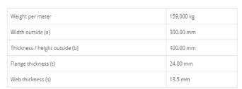
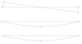

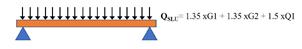
71 PRIMARY BEAM ANALYSIS: VENTILATION FIRE-SMOKE PLUMPING VENTILATIONFIRE-SMOKE PLUMPING7,5 43 6,56,57,5FBCG Area of the slab on the beam = 5.5 m × 7.5 m = 41.25 m 2 77.87.5KN/mm HEB 450 SLS : ULS : Calculations for the course Architectural Design Studio for Complex Modules Structure Prof. Luca D'Alessandro, Grigor Angjeliu Academic Year 2019-2020 In the grey cells the numbers can be hard typed. In other cells there *******************************************************************************************************************************are Part 2: Beam Total Load Calculation Influence area width I 5.5 m Linear load G1 1.8 kN/m Dead load: Beam self weight Area load G2 4.8 kN/m2 Linear load G2 26.3 kN/m Dead load: Floor Self weight Area load Q1 5.0 kN/m2 Linear load Q1 27.5 kN/m Live load: Residential Linear load G1 1.8 kN/m Dead load: Beam self weight Linear load G2 26.3 kN/m Dead load: Floor Self weight Linear load Q1 27.5 kN/m Live load: Residential Coefficient for G1 1 Coefficient for G2 1 Coefficient for Q1 1.0 TOTAL BEAM LOAD Quls 55.6 kN/m Calculations for the course Architectural Design Studio for Complex Modules Structure Prof. Luca D'Alessandro, Grigor Angjeliu Academic Year 2019-2020 In the grey cells the numbers can be hard typed. In other cells there are *******************************************************************************************************************************already Part 2: Beam Total Load Calculation Influence area width I 5.5 m Linear load G1 1.8 kN/m Dead load: Beam self weight Area load G2 4.8 kN/m2 Linear load G2 26.3 kN/m Dead load: Floor Self weight Area load Q1 5.0 kN/m2 Linear load Q1 27.5 kN/m Live load: Residential Linear load G1 1.8 kN/m Dead load: Beam self weight Linear load G2 26.3 kN/m Dead load: Floor Self weight Linear load Q1 27.5 kN/m Live load: Residential Coefficient for G1 1.3 Coefficient for G2 1.3 Coefficient for Q1 1.5 TOTAL BEAM LOAD Quls 77.8 kN/m 20.06547.03 291.75 -291.75 Calculations for the course Architectural Design Studio for Complex Constructions 1 Modules Structure Prof. Luca D'Alessandro, Grigor Angjeliu Academic Year 2019-2020 In the grey cells the numbers can be hard typed. In other cells there are already *******************************************************************************************************************************formulas.******************************************************* 1. Calculate M_ED External Bending Moment Calculation Beam Lenght L 7.5 m Linear load on beam Q_ULS 77.8 kN/m M_ED 547.0 kNm 547031250.00 Nmm 2. Choose steel class Steel class S… 355 3. Calculate fyd from the steel class fyk 355 MPa γs 1.15 fyd 309 MPa 4. Calculate Wpl Wpl 1772073 mm3 1772 10^3 mm3 5. Choose the cross section such as it has a Wpl greater than the one calculated Beam chosen HEB 450 Wpl chosen 3982 10^3 mm3 OK 2. Calculate shear force Beam Lenght L 7.5 m Linear load on beam Q_ULS 77.8 kN/m Shear force 291.8 kNm 291750000.00 Nmm 2. Choose steel class Steel class S… 355 3. Calculate fyd from the steel class fyk 355 MPa γs 1.15 fyd 309 MPa 4. Calculate Avy Avy 945105.6 mm2 945 10^2 mm2 5. Choose the cross section such as it has a Wpl greater than the one calculatedAvy greater than the one calculated Beam chosen HEB 450 Avy chosen 7966 10^2 mm2 OK 3. Deformation Beam Lenght L 7.5 m Linear load on beam Q_SLS 55.6 kN/m E 200 Gpa 200000000 KN/m2 Ix 79890 cm4 0.0007989 m4 ∆ Total (= (5/384)*((Q_SLS*L^4)/EI)) 0.014336271 m 14.336271 mm ∆ Max L/250 3 cm 30 mm OK Live load Q1 ( linar load) 5 KN/m ∆(Live Load) (= ∆(total)*(1*Q1/total load) 0.001289233 m 1.289233 mm ∆max= L/300 2.5 cm 25 mm OK Dead Load G (G1+G2) (Linar Load) 6.4 KN/m ∆(dead load) (=∆(total)*(1*G/total load) 0.00165 m 1.6502183 mm ∆max = L/300 2.5 cm 25 mm OK


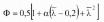
72 COLUMN LOADS AND BUCKLING CHECKS: VENTILATION FIRE-SMOKE PLUMPING VENTILATION VENTILATION ELECTRICAL FIRE-SMOKE PLUMPING VENTILATION 7,5 43 6,56,57,57,57,5FEDBACG Area of the slab on the column = 7.5 m × 5.5 m = 41.25 m 2 BOX 1000*1000*401000 mm 1000 mm Curve C α = 0.34 Φ = 0.49 Calculations for the course Architectural Design Studio for Complex Modules Structure Prof. Luca D'Alessandro, Grigor Angjeliu Academic Year 2019-2020 In the grey cells the numbers can be hard typed. In other cells there are *******************************************************************************************************************************already 1. Obtain N_ED Axial force N_ED 25830 kN 25830000 N pre-selected profile BOX 1000*1000*40 As 1536 cm2 i_min 392 mm As 153600 mm2 2. Choose steel class Steel class S… 355 3. Calculate fyd from the steel class fyk 355 MPa γs 1.15 fyd 309 MPa 4. Calculate λ l= 4 m koef= 1 lo= 4000 mm λ= 10.2 < 150 OK 5. Calculate 0.1376.4 6. Calcualte cross section area A 1 N_Rd 47416 kN 7. Check that capacity NRd > demand NEd N_Ed 25830 kN check OK N_RD 47416 kN ratio 54% ���� ����1 = ���� ���� = ������������ = ���� ���� ������������ FLOOR LOAD 1. Dead load + live load of the floor 9.79 KN/m² × 41.25 m² = 404 KN 2. Secondary beam load 1.6 KN/m × 5.5 m × 6 = 52.8 KN 3. Primary beam loads 1.8 KN/m × 3.75 m × 2 = 13.5 KN 1.8 KN/m × 5.5 m = 9.9 KN 13.5 KN + 9.9 KN = 23.4 KN 404 KN + 52.8 KN + 23.4 KN = 480 KN Per one floor per one column 480 × 48 = 23040 KN Total loads of the floors for one column ROOF LOAD 9.63 KN/m² × 41.25 m² = 397.24 KN + 52.8 + 23.4 = 473.45 KN Roof load for one column Loads from upper columns on the bottom column = 196 m × 1205.58 kg/m = 236293 Kg= 2317 KN 23040 KN + 473.45 KN + 2317 KN = 25830 KN Total load per one column 4.1: STRUCTURAL DESIGN

NED Roof = 473 KN 48 NEDFloorsFloor = 23040 KN Total NED = 25830 KN 43 m 19 m +200 m -1 m -2 m 0 m 7.5 m 7.5 m 7.5 m 7.5 m 7.5 m 7.5 m8 m 6 m 8 m6 m 8 m8 m8 m
74 TECHNICAL DRAWINGS: 4.1: STRUCTURAL DESIGN
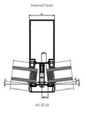
75 1 2 3 4 5 6 7 8 9 10 1 2 3 4 5 9 10 6 12 11 13 7 7 8 14 15 15 16 17 SC: 1/17 1. Reinforced Concrete 2. Insulation 3. Separation Layer 4. Screed 5. Waterproof Layer 6. Thermal Insulation 7. Vapour Barrier 8. Thermal Insulation 9. Stiffener Board 10. Coping DescriptionN° 1. Triple Glazing 2. Mullion 3. Thermal Insulation 4. Plasterboard in Calcium-Silicate 5. Tempered glass for spandrel 7. Fixing plate 8. Beam 9. Ceiling HangerDescription10.N° Suspended plates 11. BIPV panels 12. Spider Clip 6. Aluminum sheet 1. Triple Glazing 2. Mullion 3. Thermal Insulation 4. Plasterboard in Calcium-Silicate 5. Tempered glass for spandrel 14. Fixing Bracket 7. Fixing plate 8. Beam 9. Ceiling HangerDescription10.N° Suspended plates 11. BIPV panels 12. Spider Clip 6. Aluminum sheet 13. Anchoring 16. Substructure 15. Welding 17. Second skin column
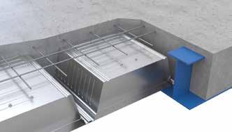
76 6 7 8 9 10 11 12 13 14 15 16 5 4 3 2 121131511 SC: 1/17 TECHNICAL DRAWINGS: 1. Flooring Tiles 2. Cement & Sand Mortar 3. Soil 4. Gravel 5. Drain Chanel 6. Insulation 7. Soil 8. Geotextile Layer 9. Stone Blockage 10. Drain pipe 11. Base plate 12. Bolts & Nuts 13. Foundation 14. Cupolex module 15. Filling concrete 16. WaterproofingDescriptionmemberN° 4.1: STRUCTURAL DESIGN
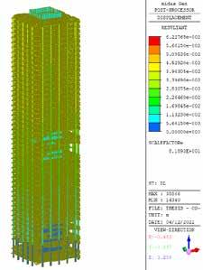
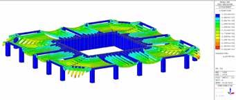
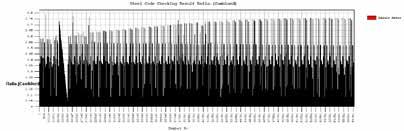
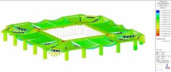
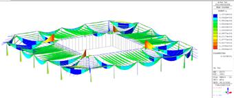
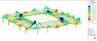
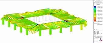
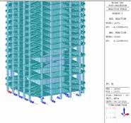
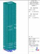
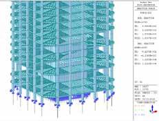
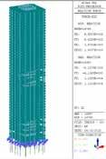
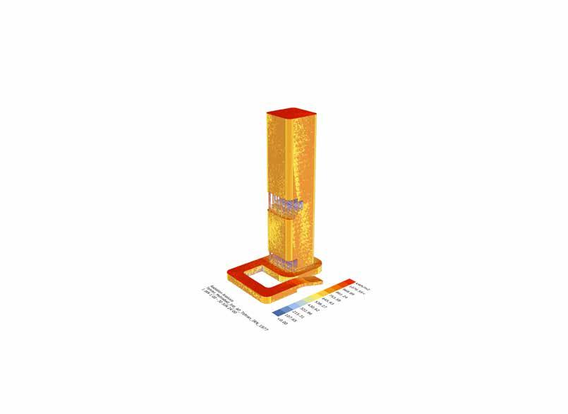
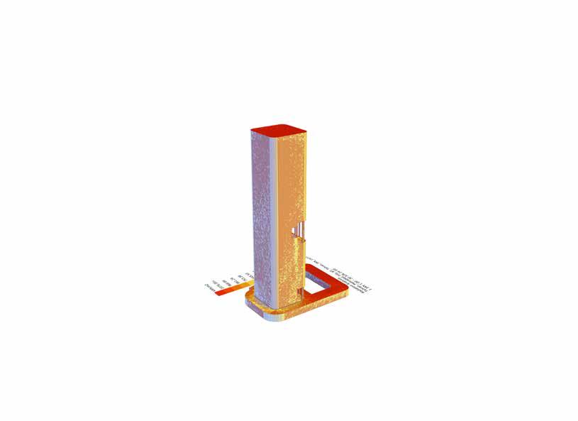
77 MIDAS ANALYSIS: • Whole tower displacement Basement displacement Basement beam Shear force Basement beam Bending moment Whole structure Bending reaction Whole structure Base reaction
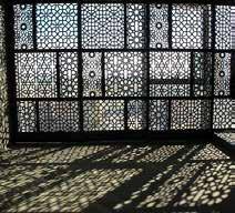
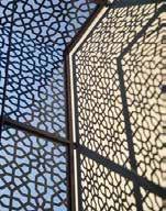
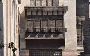
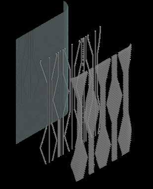
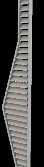
Mashrabiya or “interlaced wooden screen” is one of the most prominent traditional architectural elements in the Middle East.Mashrabiya provides interior shading while allowing air movement, which helps to reduce the temperature in the summer (Sabry and Dwidar, 2015). Mashrabiya can also be used to cover the openings, thus ensuring privacy for home occupants. In addition to its environmental and social features, it also adds aesthetic value to the building and urban space, as the Mashrabiya is generally characterized by ornamental patterns with different styles.
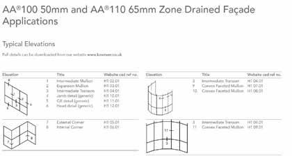
78 4.2: FACADE DESIGN
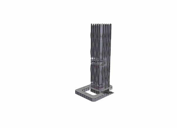
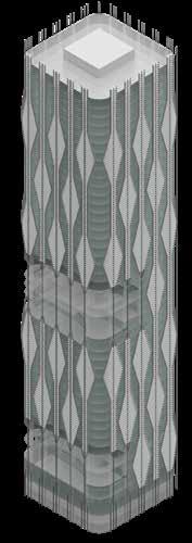
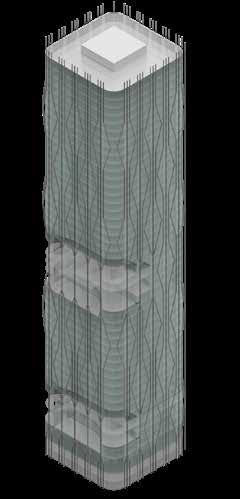
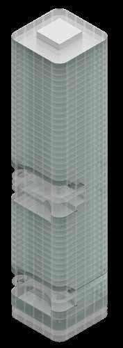
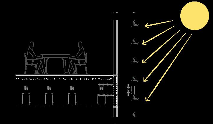
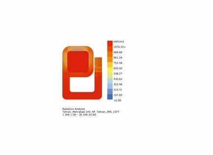
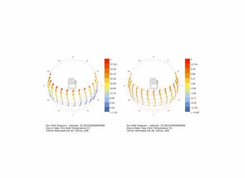
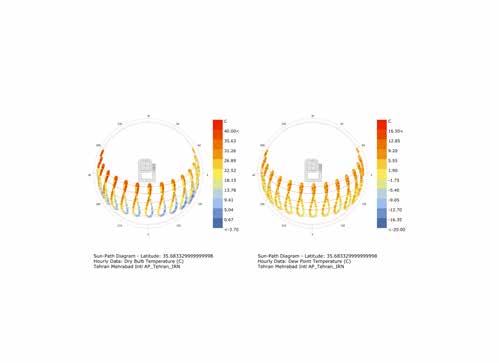
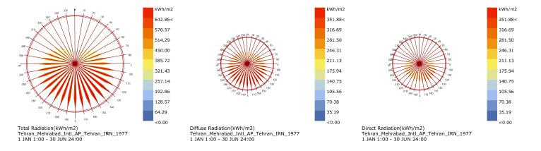
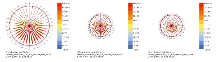
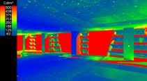
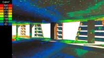
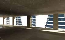
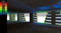
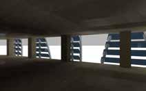
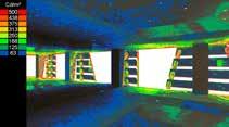
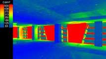
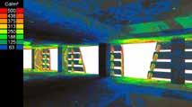
Based on ladybug sun analysis two main facade of the skyscraper (south and east) are mainly in contact with light and heat. For controlling the absorption of heat and sharpness of the sunlight especially during summer another external facade applied to the tower for improve the sustainability and management of the energy. Application of this external facade was merged with a pattern which is a representation of Persian culture patterns
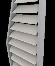
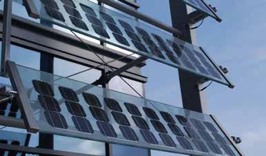
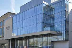
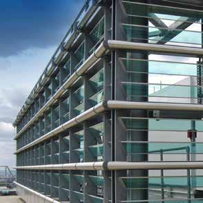
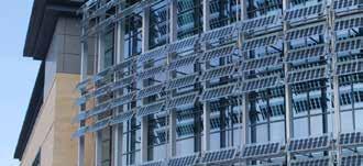
Louvre systems Shield glazed building envelopes from direct sunlight and control solar heat gain whilst still maximizing natural daylight into the louverbuilding. format allow natural ventilation of internal building spaces whilst keeping intense sunshine and moisture covered with PV for additional shading and heat reduction properties.

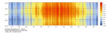
The radiation versus tilt angle in 12 p.m. for N=35.7 in Tehran.
4.2: FACADE DESIGN
80 - Limit overheating of buildings and allow to control the penetration of light and sunlight, creating a more pleasant and productive work environment and life. - Ensure the electricity production for the needs of the building or for connection to the grid.

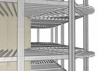
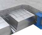
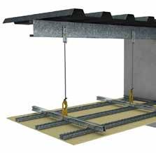
The KEY-LOCK Ceiling System enables the mixing of primary Top Cross Rail and secondary components Furring Channel to increase spans, suspension fixing points and maximise structural design.
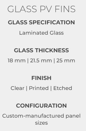
81 4.3: MATERIAL
Efficient: Cross stiffener technology and deep profile shape provides a very efficient metal deck and composite slab giving low usage of steel and concrete.
Versatile: Especially suited to bear on the extended lower flange of a steel beam, can also be used on the top flange.
Nestable: The simple trapezoidal shape neatly nests one profile into another, allowing more square metres per bundle.
Ceiling System is designed to produce a high-quality structure for a flush or featured finish to your plasterboard ceiling.
Available for non fire-rated and fire-rated applications, bulkhead, seismic and acoustic designs, it is strong enough to hold multiple layers of plasterboard.
Efficient for export: Maximises the square meterage in each container.


82 4.3: MATERIAL
Infiniti glass products can all be configured either in a fixed position or with options for manual, motor-driven or automatically-programmed adjustment to make manoeuvring the system simple. Levolux will always consult with you to find the most suitable solution. can be supplied in clear or printed / coloured formats, or covered with PV for additional shading and heat reduction properties.


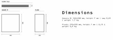
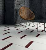
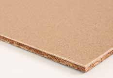
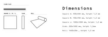
83 Floor products are designed to support the needs of everyday life. Thanks to the 87% biobased resin constituting the top aesthetic layer, Mogu Floor products are able to resist heels, scratches, abrasions just like any conventional floor.


84 4.4: BUILDING INFORMATION MODELING CONCEPT ANALYSIS LOD 100 MODELING LOD 200 ANALYSIS 7 DESIGN LOD 300 STRUCTURE & CONSTRUCTION LOD 400 FABRICATION & ASSEMBLY Site DiagramsAnalysis&SketchesLEVELWORKFLOWOFDESIGN
100 Building model at this stage reflects the process of site analysis and conceptual design phase. The model contains the approximate quantity, size, location, and systematic relationships of the most objects that will eventually be installed. 200 Building model contains the accurate quantity, size, location, and systematic relationships of all objects that will eventually be installed. The data about all objects like: typical floor plans, sections, elevations, etc will be clarified in this stage. 300 This stage is achieved when fabrication and assembly can be driven directly from the model. Sun radiation, wind analysis, daylight visualizer, energy performance and other necessary studies are applied to analyze in-depth the building effect.


85 Comfort Value Category 1.1 Daylight: 2.3 % 2.8 1.2 Thermal environment: Good level 2.9 1.3 Indoor air quality: ≤ 1000 ppm 2.7 Classification C Energy Value Category 2.1 Energy demand: 104.0 kWh/m² 3.6 2.2 Energy supply: 17.2 kWh/m² 4.0 2.3 Primary energy: 27.8 kWh/m² 3.9 Classification Active House Environment Value Category 3.1 Environmental loads: Good level 2.8 3.2 Freshwater: 24 % savings 2.6 3.3 Sustainable construction: Good level 3.5 Classification C Comfort Value Category 1.1 Daylight: 0.0 % 1.2 Thermal environment: Out of AH category 1.3 Indoor air quality: > 1200 ppm Classification Out of AH category Energy Value Category 2.1 Energy demand: 0.0 kWh/m² 2.2 Energy supply: 0.0 kWh/m² 2.3 Primary energy: 0.0 kWh/m² ClassificationEnvironment Value Category 3.1 Environmental loads: Lowest level 3.2 Freshwater: 0 % savings 3.3 Sustainable construction: Lowest level Classification Out of AH categoryMainRadarcalculation - New building None - New building 1.2 environmentThermal 1.3 Indoor air quality 2.1 Energy demand 2.2 Energy supply3.2consumptionFreshwater 3.3constructionSustainable1.1 Daylight Main calculation - New NonebuildingNew building Comfort Value Category 1.1 Daylight: 9.4 % 2.1 1.2 Thermal environment: Good level 2.2 1.3 Indoor air quality: ≤ 1000 ppm 2.1 Classification B Energy Value Category 2.1 Energy demand: 61.0 kWh/m² 2.1 2.2 Energy supply: 46.5 kWh/m² 1.9 2.3 Primary energy: 26.5 kWh/m² 3.8 Classification C Environment Value Category 3.1 Environmental loads: Good level 2.8 3.2 Freshwater: 24 % savings 2.6 3.3 Sustainable construction: Good level 2.4 Classification C Comfort Value Category 1.1 Daylight: 0.0 % 1.2 Thermal environment: Out of AH category 1.3 Indoor air quality: > 1200 ppm Classification Out of AH category Energy Value Category 2.1 Energy demand: 0.0 kWh/m² 2.2 Energy supply: 0.0 kWh/m² 2.3 Primary energy: 0.0 kWh/m² ClassificationEnvironment Value Category 3.1 Environmental loads: Lowest level 3.2 Freshwater: 0 % savings 3.3 Sustainable construction: Lowest level Classification Out of AH categoryMainRadarcalculation - New building None - New building 1.2 environmentThermal 1.3 Indoor air quality 2.1 Energy demand 2.2 Energy supply 2.3 Primary performanceenergy3.1 Environmentalloads 3.2consumptionFreshwater 3.3constructionSustainable1.1 Daylight Main calculation New Nonebuilding-New building Comfort Value Category 1.1 Daylight: 2.3 % 2.8 1.2 Thermal environment: Good level 2.9 1.3 Indoor air quality: ≤ 1000 ppm 2.7 Classification C Energy Value Category 2.1 Energy demand: 104.0 kWh/m² 3.6 2.2 Energy supply: 17.2 kWh/m² 4.0 2.3 Primary energy: 27.8 kWh/m² 3.9 Classification Active House Environment Value Category 3.1 Environmental loads: Good level 2.8 3.2 Freshwater: 24 % savings 2.6 3.3 Sustainable construction: Good level 3.5 Classification C Comfort Value Category 1.1 Daylight: 0.0 % 1.2 Thermal environment: Out of AH category 1.3 Indoor air quality: > 1200 ppm Classification Out of AH category Energy Value Category 2.1 Energy demand: 0.0 kWh/m² 2.2 Energy supply: 0.0 kWh/m² 2.3 Primary energy: 0.0 kWh/m² ClassificationEnvironment Value Category 3.1 Environmental loads: Lowest level 3.2 Freshwater: 0 % savings 3.3 Sustainable construction: Lowest level Main calculation - New building None - New building Comfort Value Category 1.1 Daylight: 9.4 % 2.1 1.2 Thermal environment: Good level 2.2 1.3 Indoor air quality: ≤ 1000 ppm 2.1 Classification B Energy Value Category 2.1 Energy demand: 61.0 kWh/m² 2.1 2.2 Energy supply: 46.5 kWh/m² 1.9 2.3 Primary energy: 26.5 kWh/m² 3.8 Classification C Environment Value Category 3.1 Environmental loads: Good level 2.8 3.2 Freshwater: 24 % savings 2.6 3.3 Sustainable construction: Good level 2.4 Classification C Comfort Value Category 1.1 Daylight: 0.0 % 1.2 Thermal environment: Out of AH category 1.3 Indoor air quality: > 1200 ppm Classification Out of AH category Energy Value Category 2.1 Energy demand: 0.0 kWh/m² 2.2 Energy supply: 0.0 kWh/m² 2.3 Primary energy: 0.0 kWh/m² ClassificationEnvironment Value Category 3.1 Environmental loads: Lowest level 3.2 Freshwater: 0 % savings 3.3 Sustainable construction: Lowest level Out of AH category Main calculation - New building None - New building 1.2 environmentThermal WITH SKINWITHOUT SKIN ENERGY PERFORMANCE /ACTIVE HOUSE


86 4.4: BUILDING INFORMATION MODELING July JanuaryDecemberJune


87 January Sunny January Overcast July Sunny July Overcast DAYLIGHT VISUALIZER


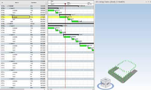
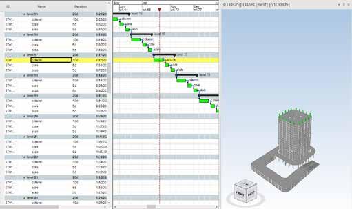
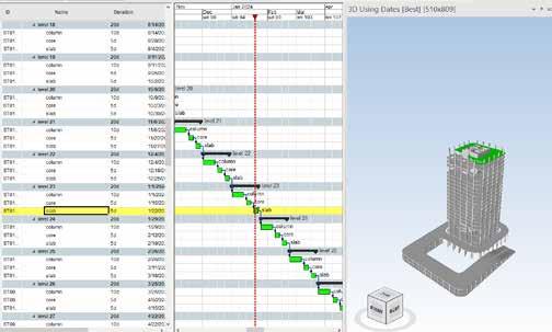
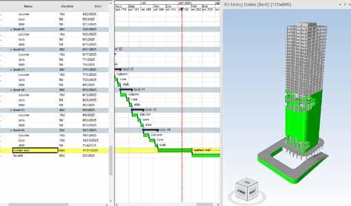
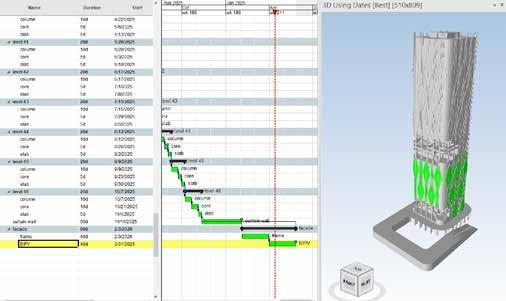
88 4.4: BUILDING INFORMATION MODELING SYNCHRO

89
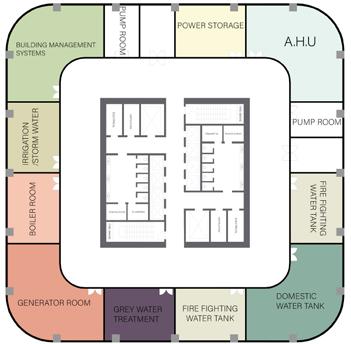
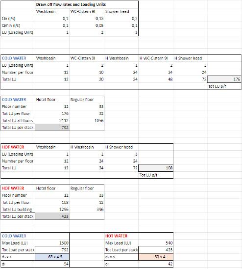
90 4.5: BUILDING SERVICES VENTILATIONELECTRICALFIRE-SMOKE PLUMPING VENTILATION Cold Water Steel Pipeline Hot Water Steel Pipeline Cold Recycled Water Steel Pipeline Cold Water PVC riser Hot Water PVC riser Cold Recycled Water PVC riser VENTILATIONELECTRICALFIRE-SMOKE PLUMPING VENTILATIONWaterDrainagesupply WATER SUPPLY AND DRAINAGE SYSTEM CALCULATIONS Hotel typical floor


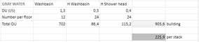


WATER SUPPLY SYSTEM Hotel typical floor 0 m 8 1321281961921881841801761721681641601561521481441401361241201161121081041001612mmm20m24m28m32m36m40m44m48m52m56m60m72m76m80m84m88m92m96mmmmmmmmmmmmmmmmmmmmmmmm64m68mmm-4m-8mVENTILATIONELECTRICALFIRE-SMOKEPLUMPING VENTILATIONVENTILATIONELECTRICALFIRE-SMOKE PLUMPING VENTILATION 2m 10m5m Cold Water Steel Pipeline Hot Water Steel Pipeline Cold Recycled Water Steel Pipeline Cold Water PVC riser Hot Water PVC riser Cold Recycled Water PVC riser DRAINAGE SYSTEM Hotel typical floor 0 m 8 1612mmm20m24m28m32m36m40m44m48m52m56m60m72m76m80m84m88m92m96m100m104m108m112m116m120m124m136m140m144m148m152m156m160m164m168m172m176m180m184m188m192m196m64m68m128m132m-4m-8mVENTILATIONELECTRICALFIRE-SMOKEVENTILATIONVENTILATIONELECTRICALFIRE-SMOKE PLUMPING VENTILATION 2m 10m5m Black Water drainage Pipeline Grey Water drainage Pipeline Black Water Vertical stack Grey Water Vertical stack
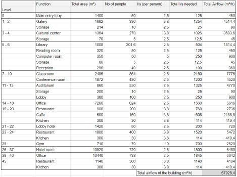
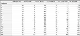
92 HVAC SYSTEM Office typical floor 0 m 8 1612mmm20m24m28m32m36m40m44m48m52m56m60m72m76m80m84m88m92m96m100m104m108m112m116m120m124m136m140m144m148m152m156m160m164m168m172m176m180m184m188m192m196mAHUAHUAHU 64 m 68 132128mmm-4m-8m2m 10m5mPrimary Air duct Return Air duct Primary air Vertical duct Return air Vertical duct VENTILATIONELECTRICALFIRE-SMOKEPLUMBING VENTILATIONVENTILATIONELECTRICALFIRE-SMOKE PLUMBING VENTILATION O1 O2 O3 O4 O8O6O5O7 O9O10O11O12 O13O14O15O16 A B C D 4.5: BUILDING SERVICES

2m 10m5m Light CableBulbConnection VENTILATIONELECTRICALFIRE-SMOKEPLUMPING VENTILATIONVENTILATIONELECTRICALFIRE-SMOKE PLUMPING VENTILATION
FIRE PROTECTION SYSTEM Office typical floor ELECTRICAL SYSTEM Office typical floor 0 m 8
1612mmm20m24m28m32m36m40m44m48m52m56m60m72m76m80m84m88m92m96m100m104m108m112m116m120m124m136m140m144m148m152m156m160m164m168m172m176m180m184m188m192m196m64m68m128m132m-4m-8m
1612mmm20m24m28m32m36m40m44m48m52m56m60m72m76m80m84m88m92m96m100m104m108m112m116m120m124m136m140m144m148m152m156m160m164m168m172m176m180m184m188m192m196m64m68m128m132m-4m-8m
2m 10m5mSprinklerWatervertical pipeline VENTILATIONELECTRICALFIRE-SMOKEPLUMPING VENTILATIONVENTILATIONELECTRICALFIRE-SMOKE PLUMPING VENTILATION 0 m 8
BIBLIOGRAPHY
By Mark Sarkisian Kheir Al-Kodmany, University of Illinois,(2012) ,The Logic of Verti cal Density: Tall Buildings in the 21st Century City,Research Paper Eldemery Ibrahim(2007) ,High- Rise Buildings –Mahmoudi Farahani, Motamed, Elmira Jamei, and Scientific quarterly journal of the facaulty of architecture and art of kashan university, Sixth year, No.11, spring and summer Kamranzad, Hossein Memarian, and Mehdi Zare, Earth quake Risk Assessment for Tehran, Iran. Mohammad Karim Pirnia, Gholamhossein Memarian, Stylistics of Annette Gigon, Mike Guyer, Felix Jerusalem, eds. Residential ANSI/ASHRAE Standard 62.1-2013. Ventilation for. Acceptable. Indoor Air Quality.
11.
10.
18.
961. Tehran disaster mitigation and management organization (TDM MO) www.tdmmo.tehran.ir 2. isna.ir 3. Mahsa Moghadasa, Asad Asadzadeha, Athanasios Vafeidisb, Al exander Feketec, Theo Köttera, A multi-criteria approach for assess ing urban flood resilience in Tehran, Iran 4. Parham Pahlavani, Hossein Sheikhian, Behnaz Bigdeli, Assessment of an air pollution monitoring network to generate urban air pol lution maps using Shannon information index, fuzzy overlay, and Dempster-Shafer theory, A case study: Tehran, Iran 5. Sadaf Safaai, P.E. Regional Workshop on Urban Water and Sanita tion Services in South and South-West ASIA, Kathmandu, Nepal (9-10 August 2017)Tehran Metropolitan Urban Water and Sanitation Man agementIslamic Republic of Iran 6. Behnam Andik, Amin Sarang, daylightinf buried and streams in 9.8.7.Tehranwww.architecture.org.auKenYeang,BioclimaticArchitectureDesigningTallBuildings:StructureasArchitecture
Per sian Gardens: Meanings, Symbolism, and Design 14. whc.unesco.or 15. M. Talebian, Recognizing
Needs & Impacts 12. worldarchitecture.org 13. Leila
characterizing thrust faults and earthquakes in Iran 16.
Iranian Architecture 19.
Bahareh
2017 17. Farnaz
Towers 20.
