”Experienced architect with extensive work background in international companies. Proactive, self-reliant, with strong attention to details.
I have experience with several types of architectural projects worldwide. I have matured the ability to implement projects in both modern architectural designs, as well as in conservation and restoration projects.”
- Bao Khanh Phan -khanhphan.arch@gmail.com
(+39)********03
linkedin.com/in/Bao-KhanhPhan
 From Ho Chi Minh city, Vietnam Living in Rome, Italy.
EDUCATION
2021 - 2023
La Sapienza University di Roma, Rome, Italy
Master of Architecture (Conservation)
2009 - 2014
HCM University of Architecture, Ho Chi Minh city, Vietnam
Bachelor of Architecture
2011 - 2015
Ho Chi Minh Sejong Center, Ho Chi Minh city, Vietnam Korean language Course
06/2013 - 08/2013
Ho Chi Minh University of Science, Ho Chi Minh city, Vietnam Creativity Methodologies Course
2004 - 2009
Nguyen Huu Huan High School, Ho Chi Minh city, Vietnam
WORK EXPERIENCE
2023 - Present
Work freelance in architectural and design fields
2021 - 2023
Professional development at Sapienza university: study and practice on conservation projects, especially in Rome.
2017 - 2020
B+H Architects Ltd - HCM Studio, District 1, HCM city,Vietnam Junior Architect (skills in Healthcare & Hospitality)
2015 - 2017
Atlas Industries Ltd. Tan Binh District, HCM city,Vietnam Junior Architect (skills in British building works)
2014
New Asia Co, LTD. Tan Binh District, HCM city, Vietnam Internship
EXTRA EXPERIENCE CERTIFICATES
06/2022
Civis school: Multiculturalism and Cultural Heritage Rediscover, tell and share the visual imprints and fragments of the metamorphosis of some areas in Rome, Italy
10/2019
V.E.O (Volunteer for Education)
Conservation Khmer Culture in Tra Vinh Province, Vietnam Kompong Thmo Pagoda, Chau Thanh Town, Tra Vinh Province
2014
Jotun paints and Homeclick.vn Children’s Colours Campaign, Vietnam School for disabled children, Binh Thanh District, HCM city
Revit Architecture 2016 Certified Professional By Autodesk, in Atlas Industries Ltd
Certificate of Completion of the Korean - level Intermediate 2016 By Youngsan University
Revit Architecture 2015 Certified Professional By Autodesk, in Atlas Industries Ltd
Training Creativity Methodologies Certificate 2013 By TSK Center, University of Science
Certificate of Completion of the Korean - level Elementary 2013 By Chosun University
LANGUAGES SOFTWARE SKILLS

OTHER SKILLS


HALONG BAY HOTEL AND CONDOTEL
Project type : HOSPITALITY
Location : Quang Ninh Province, Vietnam
Scale : 17, 243 sqm
Client : Tri Duc Group
Status : Design Development
Architecture firm : B+H Architects
Located in the center of Quang Ninh province, this project is considered as an iconic of hotel for tourism in here. The project was built with the expectation that visitors will have the opportunity to experience the world’s leading comfort and luxury services from the first moment to travel in Ha Long. This is my very first Vietnam large scale project that I managed tasks and coordinated information relevant to projec under the guide of a senior architect.
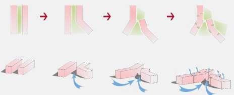
MASSING CONCEPT :
The idea of sailing boat when this building observed from a distance. A symbolic perspective is selected as a concept to help identify its function and make it highly recognizable. This building is included 2 towers with differrent functions: hotel and condotel.

VISTA PLAN


FUNCTION DIAGRAM


MY ROLE :
Key Architect of this project for both buildings, leading a small team with 3 junior architects.
Co-ordinate with Structural drawings, Landscape and MEP drawings to find resolutions for Architecture.
Use Revit to set up drawings sets for team to work. Deliver drawings and 3D models for clients.
Find out solution for BMU (building maintenance unit), Fire strategy for building.


PODIUM ROOF PLAN


40 LEADENHALL STREET
Client : TH Real Estate Status : Design Development Architecture firm : Make Architects
MASSING CONCEPT :
The assembled elements create a striking and harmonious composition within its urban context which breaks down the mass of the building from certain angles and mediates between the height and scale of adjacent tall towers to the north and west, and lower buildings to the east and south.
This is my very first working project, which I learned many things about working on a large scale project.
The design for 40 Leadenhall Street is a new skycrapper in the City of London ‘s insurance district. The architectural concept is reminiscent of the vertical expression and solidity of some of the grand 20 Century North American buildings. It also respect its historic surroundings, protect the view of St’s Paul Catheral and stay sympathetic to 19-21 Billiter Street a grade II - listed building on the site.
“40 Leadenhall Street is one of the biggest schemes to ever receive planning permission in the City of London.”
MY ROLE :
Revise model and Design Development drawings.
Modeling the visualization of the facade according to a senior architect. Involve in various packages including Fire strategy drawings, Staircase, RCP layout using Micro Station and Aecosim. Follow the regulation to model details of cladding for facade. v


COLUMBIA CHINA JIAXING HOSPITAL
Project type : HEALTHCARE
Location : Shanghai, China
Scale : 120, 000 sqm
Client : Columbia China
Status : Construction Development
Architecture firm : B+H Architects
MASSING CONCEPT :
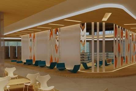
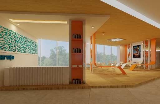
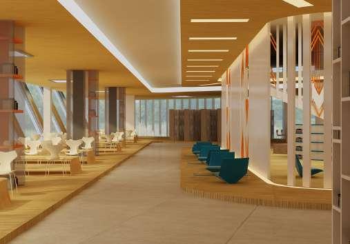
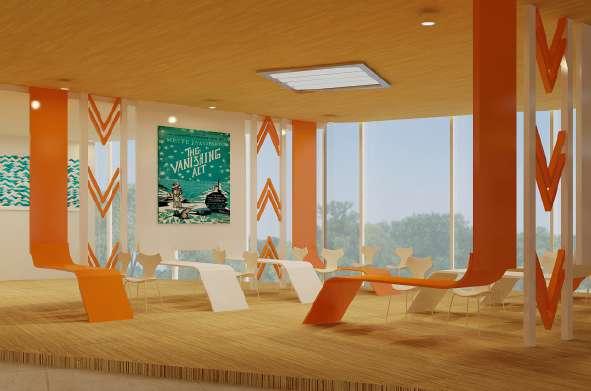
This project is a healthcare project, located in Shanghai. The interior design concept is based on a symbolic plant (ginko leaves form) which is similar to architecture form of this building. To help identify its function and make it highly recognizable, each department is designed in different colours illustrating 4 seasons in a year.
MY ROLE :
Provide a package of ID design according to Design architect. Model 3D families of special equipment for each room using Revit, based on descriptions from vendors. Layout room plans according to the sketches, following the Shanghai regulation of Healthcare projects.


3D VIEW


THE AURELIAN WALL METRONIA GATE
Project type : LANDSCAPE
Location : Porta Metronia
The Aurelian’s wall, Rome, Italy
Status : Conservation/ Intervention concept
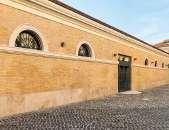
The Porta Metronia opens from the surface of the Aurelian Walls. It is located along the Via dell’Amba Aradam, which leads to Basilica of Saint John In Lateran; the gate is situated in the southern part of the wall.
CURRENT CONDITION :
Aurelian wall was a defensive wall to protect Rome from enemies invading. The construction began in 3rd century AD and finished within around 5 years.
The gates of Aurelian wall
(Adapted from Plan of Ancient Rome, English)
Metronia opens from the surface of the Aurelian Walls. Different names (Metrodia, Metaura) were given for this gates over time, but the all seemed to deviate from the Metrovia, which perharps derived from some Metrobius or Metronianus who apparently had possessions in the area, during the late empire.
Porta Metronia was the third class gate with the simple opening in the brick curtain. The height of the wall changed because the level of street was raised up, burying the lower part including the gate.
Gabiusa was another name for it, due to the fact that this used to be where the road leading ancient city of Gabii began. This road more or less corresponds to Via Gallia in present.
PRESENT SITUATION
HISTORICAL STUDY
URBAN EVOLUTION OF ROME

Porta Metronia and its surroundings

LEGEND OF THE STREET :
Via della Navicella - directly to Colosseum monument
Via Druso
Via dell’ Amba Aradam - directly to Basilica Saint
John Lateran
Via della Ferratella in Laterano
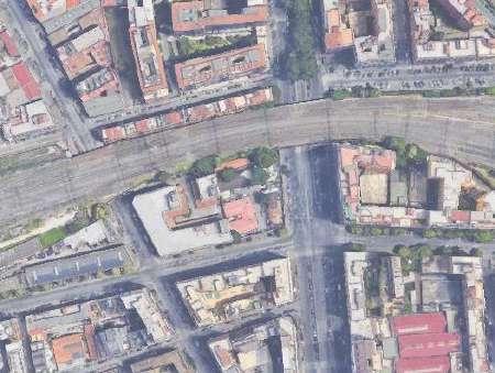
The railway has been built in 1961, and the agricultural land near the Porta Metronia has

TIMELINE FOR THE SURROUNDINGS


It
Via della Navicella - directly to Colosseum monument
The the the buried beneath
The which outside 12th interior peperino tiles
The ancient walls in Rome
Via Druso
Via dell’ Amba Aradam - directly to Basilica Saint John Lateran
CONSERVATION WORKS :
Region Lazio, Italy
Via della Ferratella in Laterano
Positon

The gate currently exhibits the appearance it had during the medieval era, having been buried at least 1.50 meters beneath the surface.
City Rome
Porta
1850

Region Lazio, Italy
City Rome
Positon
The 3.22 m wide fornix arch, which is more noticeable on the outside wall, is ornamented with 12th century brick work; the interior is padded with erratic peperino pieces combined with tiles and tuff
Porta
According to the ana�ysis, Rome was expanded, which �ed to the near�y comp�eted deve�opment of urban p�anning system under the Empire.
Built 271 - 275 AD
Roman wa��s are thought to have grown a�ongside the city even though, as seen by Rome’s expansion, they were a�ways �arger than the sett�ement area.
Built by Imperial Aurelian Type
* Bib�iogra�h�
Aurelian Wall of Rome
Aurelian Wall of Rome
Porta Metronia situated in the southern
Built 271 - 275 AD
Built by Imperial Aurelian
Type

Defensive wall
Materials Bricks, Mortar, Concrete
Porta Metronia situated in the southern part of the wall
(Picture from website romanoimpero.com) Honorian III still mentioned about the marsh outside the Porta Metronia 1217. plan of Roman forum, the swamp appeared as a problems in 1706 - 1707, at the time of Pope Clement XI : “I tried didn’t succeed”. After 70 years, until the excavation of the forum was resumed, the swamp was fulfilled and raised the most of the gate underground.” - Lanciani wrote century, the original structure of 2 sides of the gate was replaced with more modern archways, they were opened traffic.
The Marana, in channeling into the pipeline under the door, probably formed a stagnation which was the cause of many epidemics, such as the serious one in 1601.
After doing all analysises of the current situation to find out the original shape and materials through periods, some preservation methods such as: cleaning vegetation on the surface, reinforcing wall cracks, restoring lack of materials are recommended for a plan of maintaining the current existing wall. Furthermore, based on information collected, a theoretical intervention solution was proposed with the goal of ensuring that residents and visitors have a clarified understanding of the old fortification structure, which will be converted into an archeology park in the future.
The ancient walls in Rome through the ages
A�� pictures from Muratori, S., Bo��ati, R., Bo��ati, S., Marinucci, G. (1��3) � The urban evo�ution of Roma from the ear�y sett�ement to modern times.
Defensive wall Materials
(www.portametronia.it)
Bricks, Mortar, Concrete gate currently exhibits appearance it had during medieval era, having been least 1.50 meters the surface. 3.22 m wide fornix arch, more noticeable on the wall, is ornamented with century brick work; the is padded with erratic pieces combined with tuff.
In the beginning of XX century, with the construction works of Archeological Walk, all the landfill was unloaded, causing a considerable elevation of the floor and completely burying the
General conclusion:
The development of Picture from website
The gate with the passage of water under, XVII century.
Since the earliest stages of Rome has constantly used defensive stop intruders since its founding. cohesive structure, but rather multiple walls from various historical eras using diverse methods in accordance weapons available at the time, ranging
HISTORICAL STUDY AND CONSERVATION PLAN OF THE CITY WALL OF ROME 01""'� Sapienza Universita di Roma -Master in Architecture (Conservation)
HISTORICAL STUDY AND CONSERVATION PLAN OF THE CITY WALL OF ROME CLOSE TO PORTA 01""'� Sapienza Universita di Roma -Master in Architecture (Conservation) Supervisor : Prof. Rossana
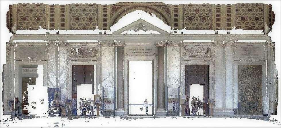
VI. MASONRY ANALYSIS - THE LATERAL WALL CLOSE TO PORTA METRONIA
VI. MASONRY ANALYSIS - THE LATERAL WALL CLOSE TO PORTA METRONIA
MASONRY MAPPING ON THE INTERNAL FACADE 1: 100
MASONRY MAPPING ON THE INTERNAL FACADE 1: 100
ANALYSIS - THE LATERAL WALL CLOSE TO PORTA METRONIA
ON THE INTERNAL FACADE 1: 100

Student: Phan Lam Bao Khanh 1953533


Supervisor : Prof. Rossana Mancini
HISTORICAL STUDY AND CONSERVATION PLAN OF THE CITY WALL OF ROME CLOSE TO PORTA METRONIA Sapienza Universita di Roma -Master in Architecture (Conservation)


INTERVENTION’S IDEA :


The proposal is to create an archaeological area outdoor where for inhabitants to experience the defensive wall from its historical evidences of the wall.
It takes into account the transformation of the present area into a green connection location. The area outside was designed for pedestrians partly understanding the structure and having feelings of the original height of the Aurelian wall in the past.


DESIGN PLAN AND MATERIALS


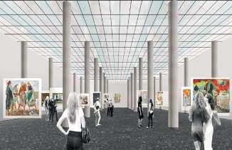
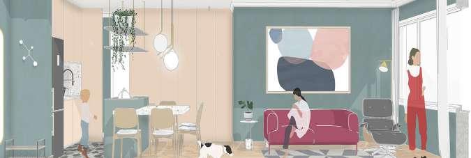
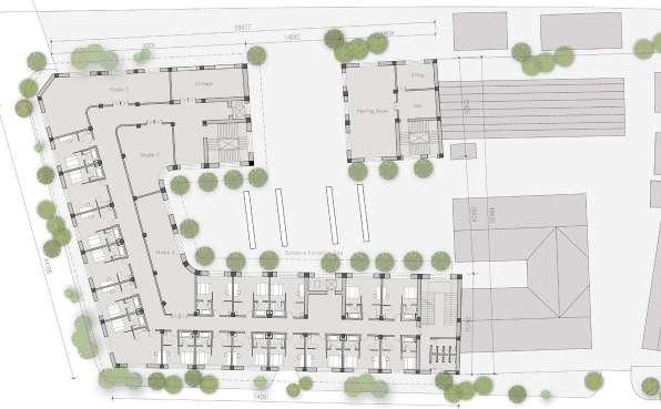
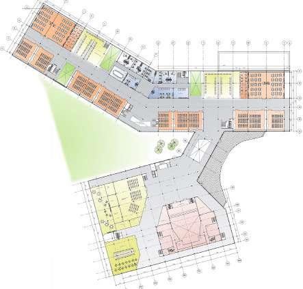
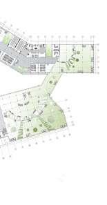
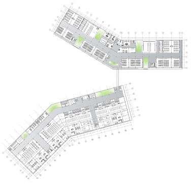
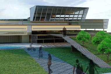
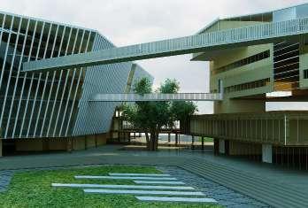
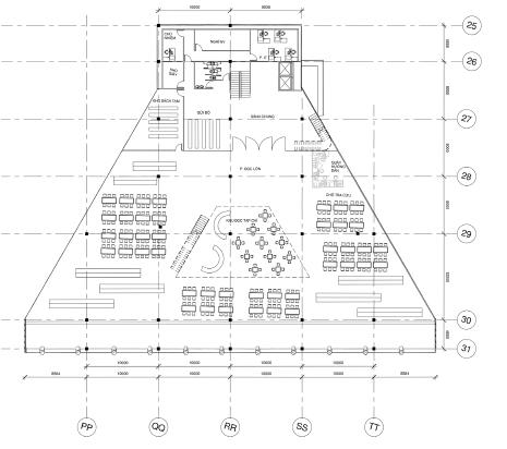
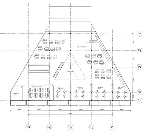
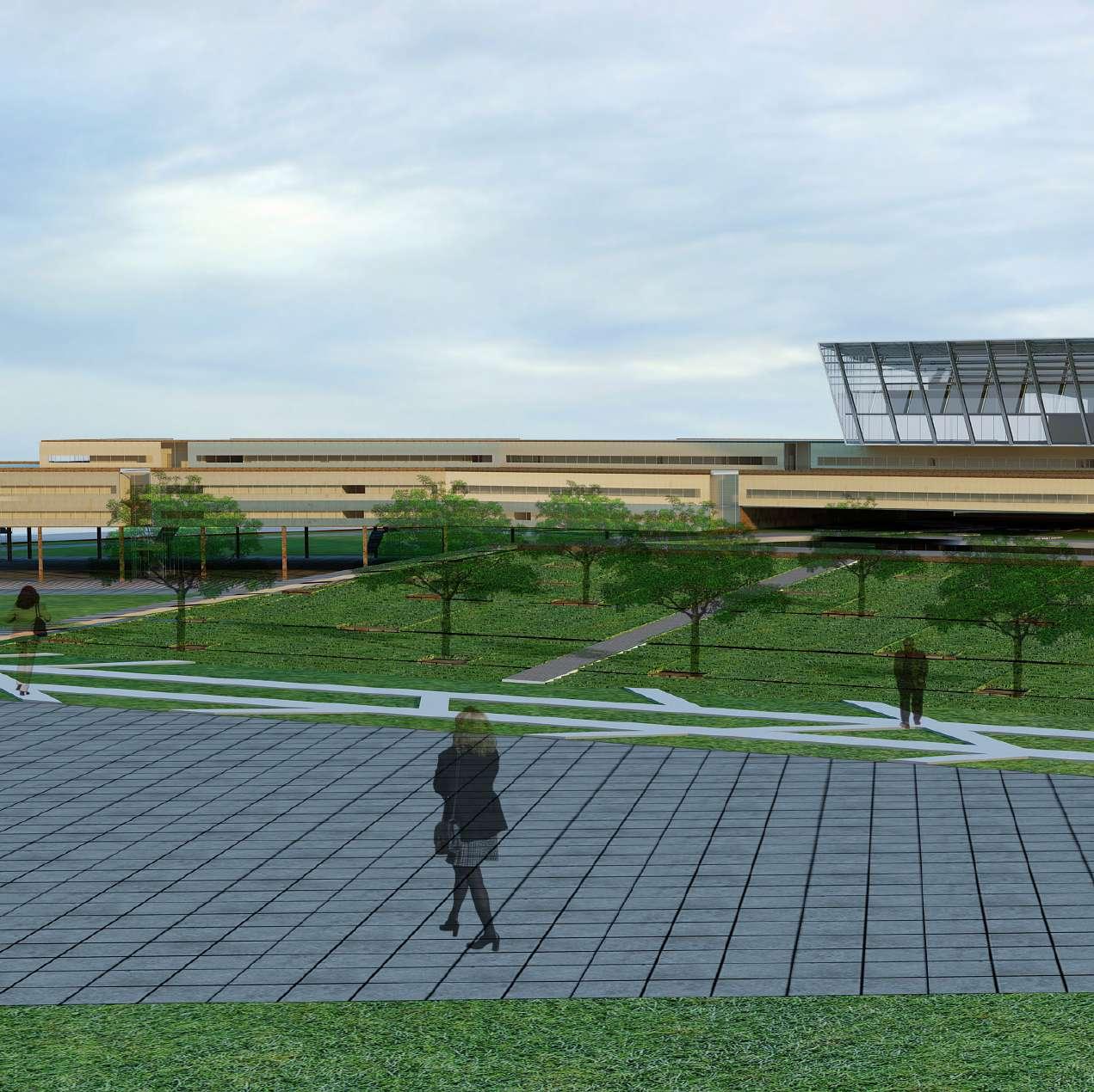
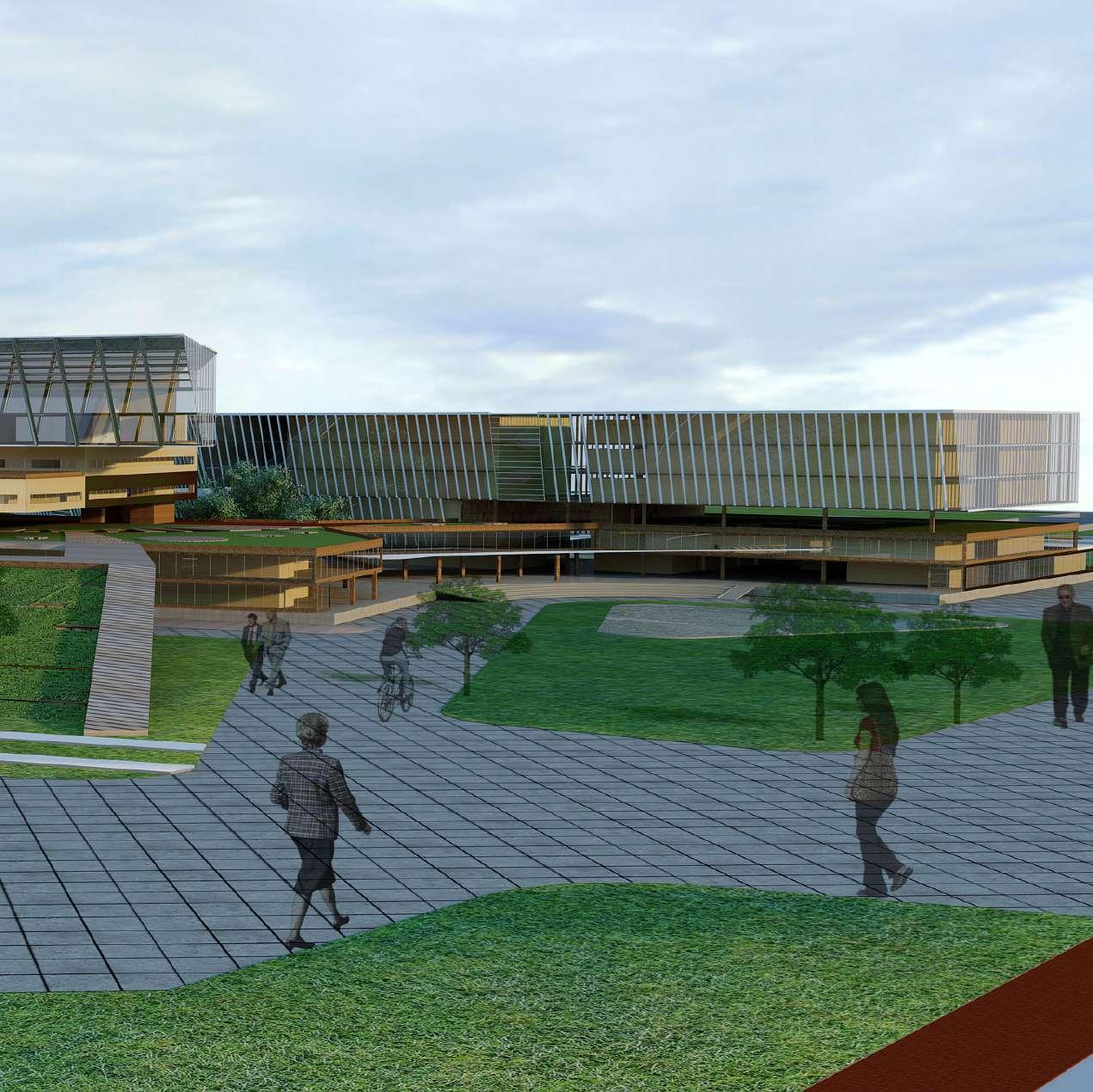
THE SCHOOL OF ARTS
Project type : INSTITUTIONAL/ EDUCATION
Location : An art school for children
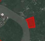
Testaccio - Ostiense, Rome, Italy
Status : Design/ Concept
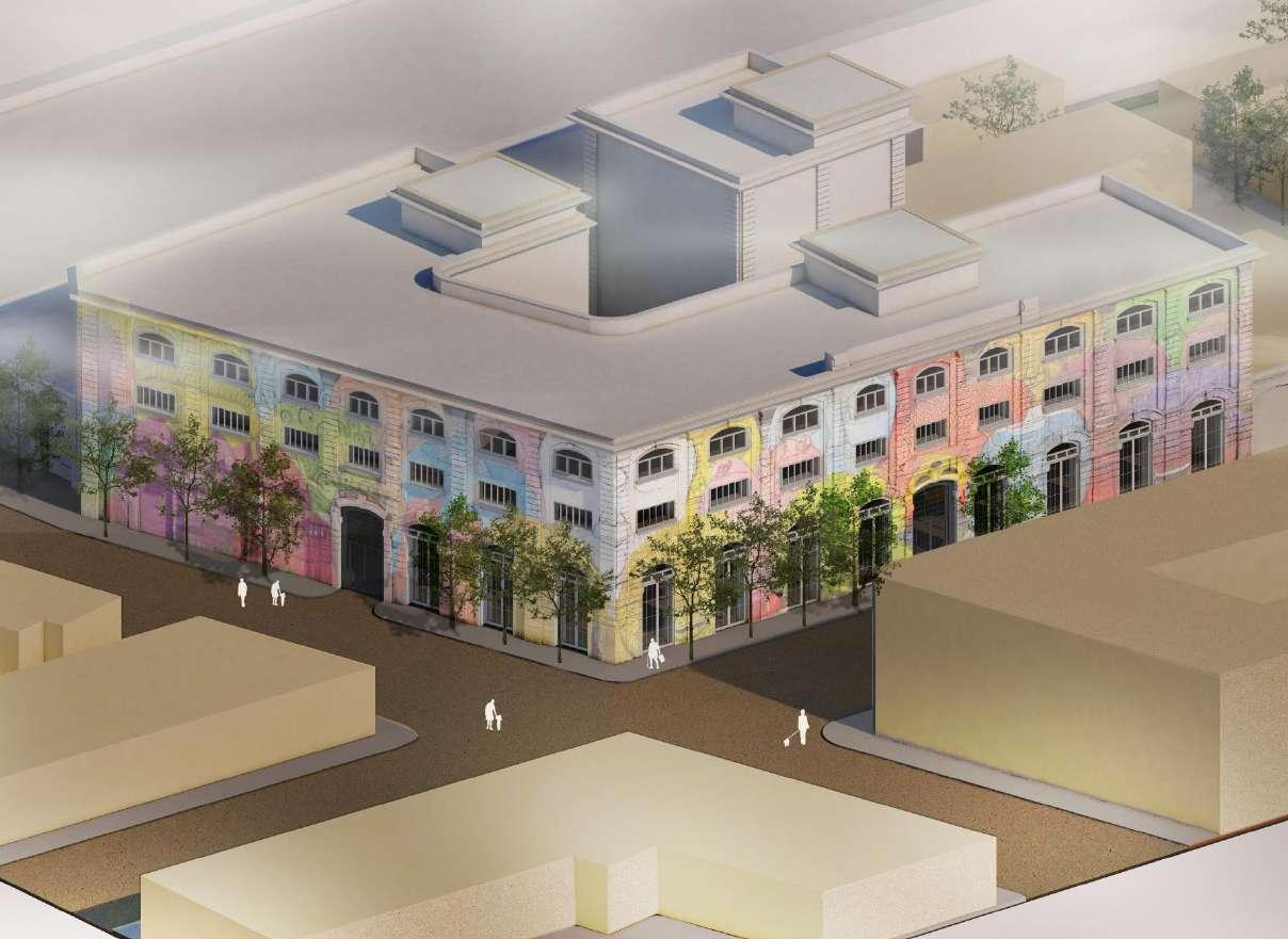
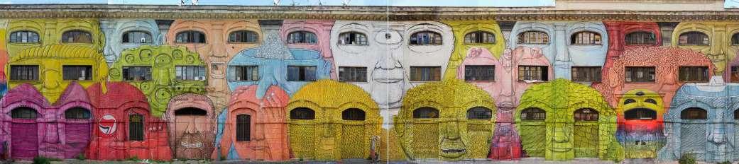
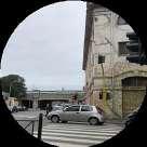
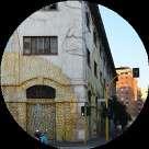
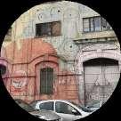
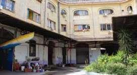
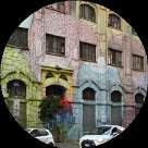
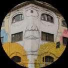
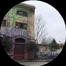
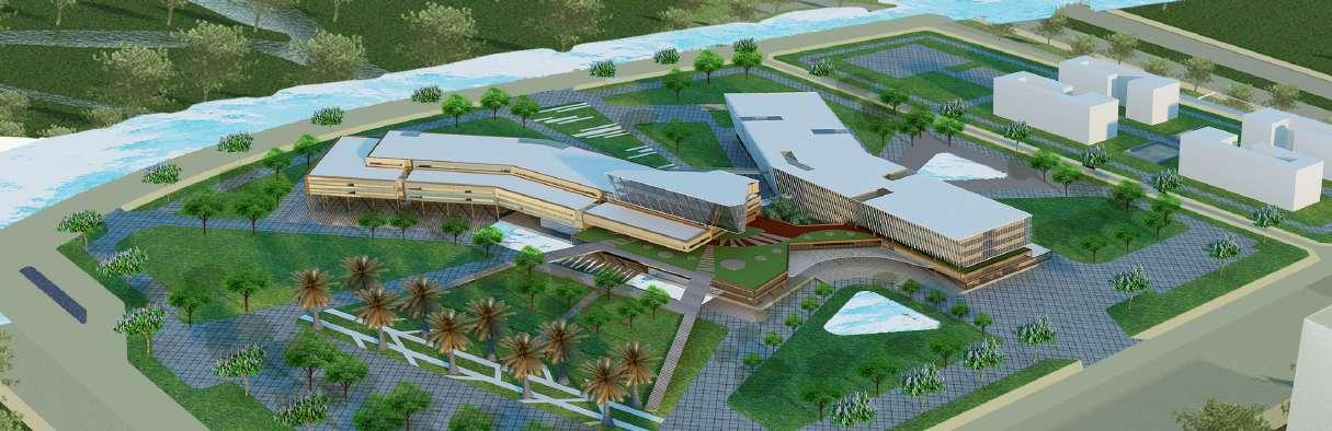
The project area is located in the Testaccio area in Ostiense, Rome. After the war, it was planned to become an industrial district; and currently this area slowly becoming a district of sensation arts, but many abandoned slaughterhouse and workers’s buildings still existed.
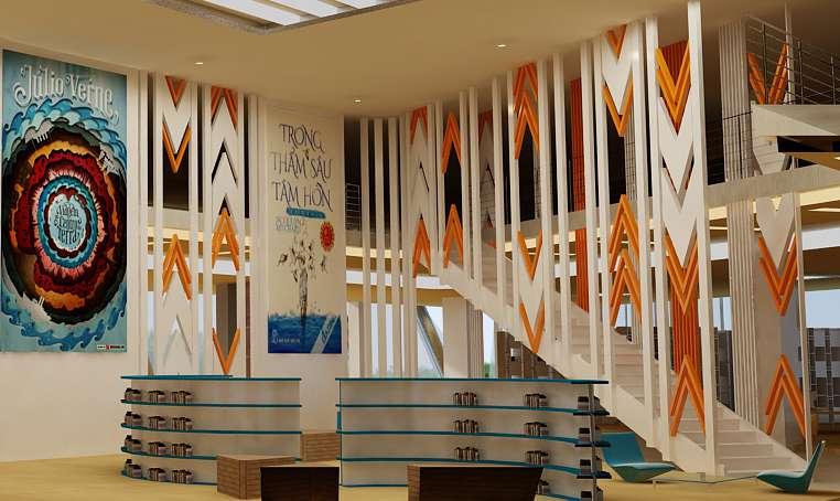
THE DESIGN’S IDEA :
An hypothesis design used the inherrited structure that already exist to introduce a new functions of the arts school.
The area located in the 1900 historical context, therefore the design includes the transformation of existing buildings and the proposal of new adding architectural elements as well as rethinking of the new masterplan for the area.


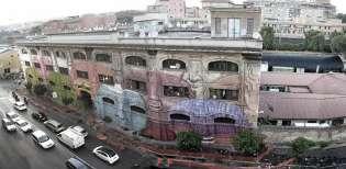
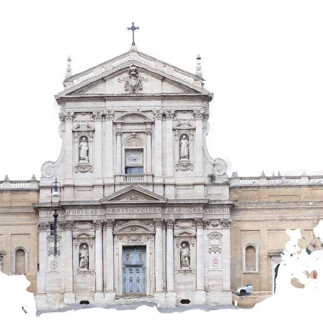
HISTORICAL AND PRESENT CONTEXT


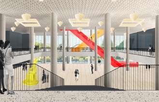
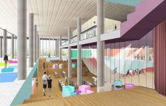
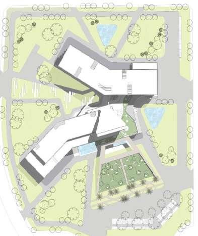
The first concept is 2 symmetrical buildings, through the main axe connecting from the entrance to the river bank. Part of the slaughterhouse and two already existing buildings will be remained with the interior renovation to get a new main function as arts classes , and added a smaller block between to create a general space linked 3 seperated buildings together.
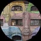
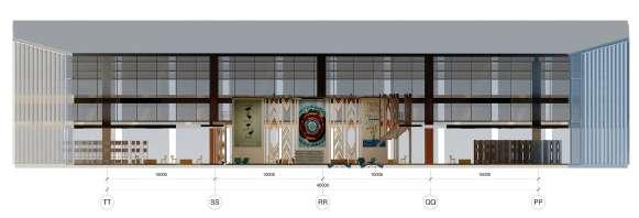
With the idea about the opposition between past and future, as the need of the school and inhabitants there, a new auditorium added with the structure repeated from the slaughterhouse’s arc windows,to make the visual balance of this area.

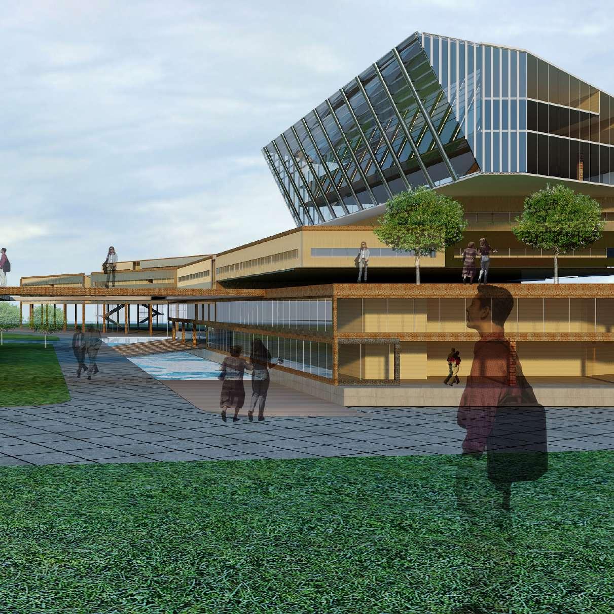
CONCEPT


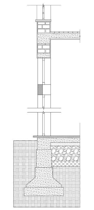
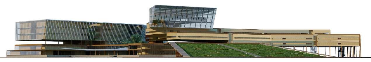
GENERAL ELEVATION

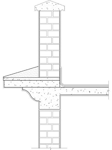
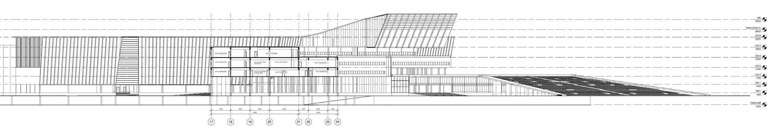
GENERAL SECTION

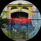
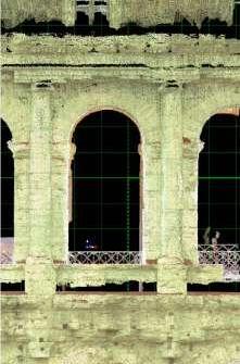
HOW TO TRANSFORM THE OLD SLAUGHTER HOUSE TO CLASSROOMS


The abandoned slaughterhouses existing between Monte Testaccio and the ancient Aurelian Wall (according to the master plan from 1868 to 1891) is one of the important parts which will be turned into moderned studying spaces.
The reference is the Mattatoio, which has been transformed into a multipurpose complex performing arts. This project also decided to maintain the exterior of buildings and renovate the interior equipped with large classrooms and spaces for students, create hallways to link spaces and organize small exhibitions from students in parallel.

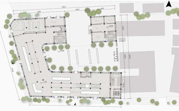
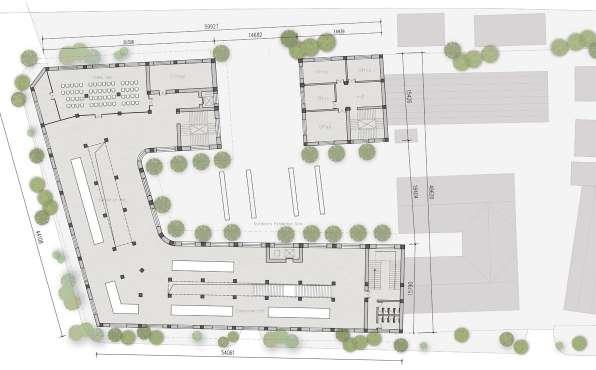
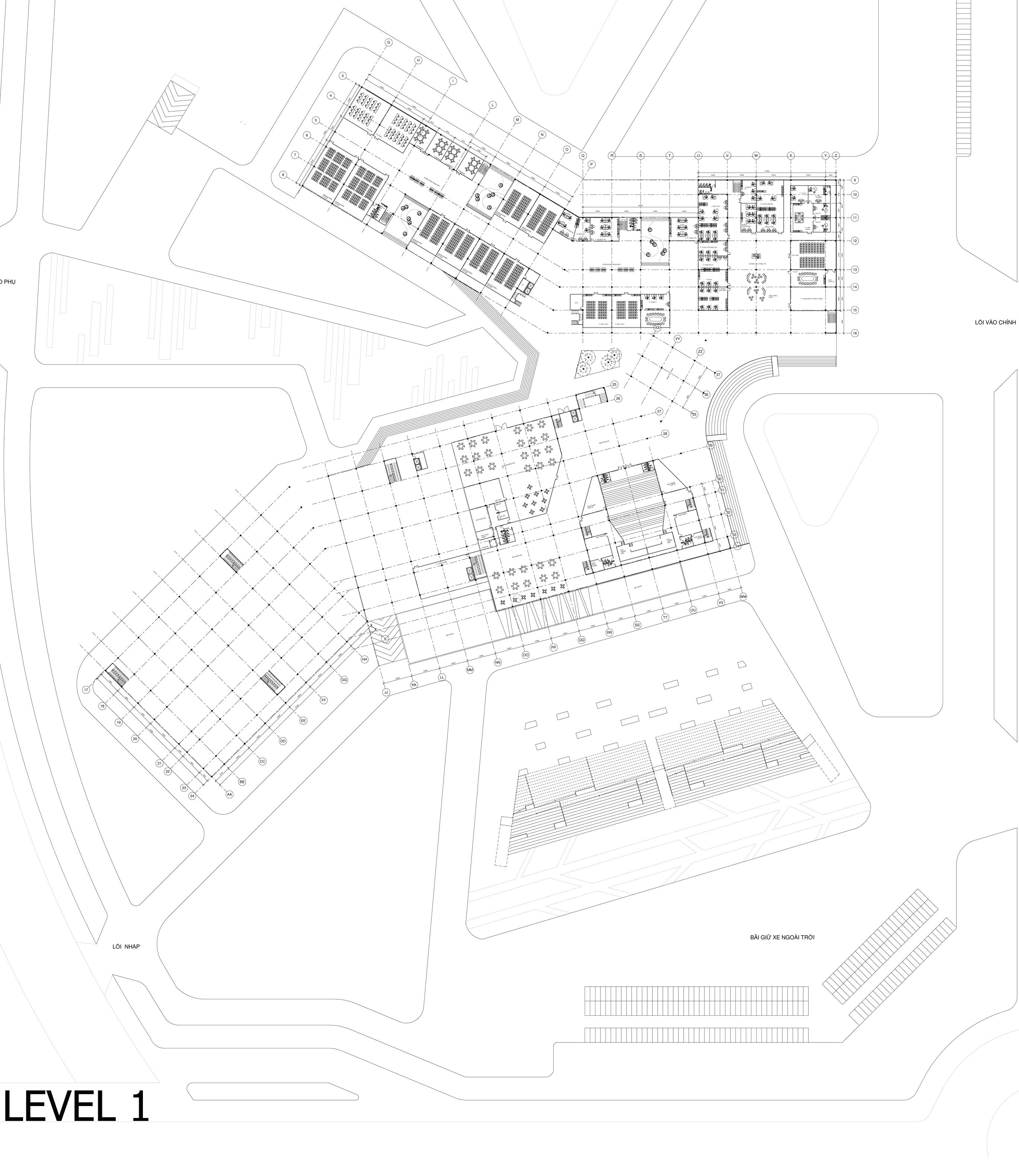
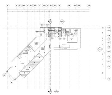
GROUND FLOOR PLAN


ELEVATION OF THE SCHOOL