
6902285 (2-06) © Bobcat Company 2006 Service Manual S/N 522811001 & Above S/N 522911001 & Above 316 Printed in U.S.A.
MAINTENANCE SAFETY
Instructions are necessary before operating or servicing machine. Read and understand the Operation & Maintenance Manual, Operator’s Handbook and signs (decals) on machine. Follow warnings and instructions in the manuals when making repairs, adjustments or servicing. Check for correct function after adjustments, repairs or service. Untrained operators and failure to follow instructions can cause injury or death.
W-2003-0903
CORRECT
CORRECT
CORRECT
B-10731a
Never service the Bobcat Hydraulic Excavator without instructions.


Have good ventilation when welding or grinding painted parts.
Wear dust mask when grinding painted parts. Toxic dust and gas can be produced.
Stop, cool and clean engine of flammable materials before checking fluids.
Never service or adjust machine with the engine running unless instructed to do so in the manual.

Avoid contact with leaking hydraulic fluid or diesel fuel under pressure. It can penetrate the skin or eyes.
Never fill fuel tank with engine running, while smoking or when near open flame.

B-15797
Use the correct procedure to lift and support the excavator. Always lift the blade fully before installing jackstands.

Cleaning and maintenance are required daily.
Vent exhaust to outside when engine must be run for service. Exhaust system must be tightly sealed. Exhaust Fumes can kill without warning.
Always lower the bucket and blade to the ground before doing any maintenance.
Never modify equipment or add attachments not approved by Bobcat Company.
Keep body, jewelry and clothing away from moving parts, electrical contact, hot parts and exhaust.
Wear eye protection to guard from battery acid, compressed springs, fluids under pressure and flying debris when engines are running or tools are used. Use eye protection approved for type of welding. Keep side access covers closed except for service.
Lead-acid batteries produce flammable and explosive gases. Keep arcs, sparks, flames and lighted tobacco away from batteries.
Batteries contain acid which burns eyes or skin on contact. Wear protective clothing. If acid contacts body, flush well with water. For eye contact flush well and get immediate medical attention.
Maintenance procedures which are given in the Operation & Maintenance Manual can be performed by the owner/ operator without any specific technical training. Maintenance procedures which are not in the Operation & Maintenance Manual must be performed ONLY BY QUALIFIED BOBCAT SERVICE PERSONNEL. Always use genuine Bobcat replacement parts. The Service Safety Training Course is available from your Bobcat dealer.
Safety Alert Symbol: This symbol with a warning statement, means: “Warning, be alert! Your safety is involved!” Carefully read the message that follows. MSW26-0805
B-15798WRONG
WRONG
WRONG B-15799
B-15800 WRONG B-15801 WRONG B-19806
B-16102 B-19807 WRONG B-16102 B-6589
ALPHABETICAL INDEX
INSTRUMENT PANEL ............................................50-01 ISO HYDRAULIC CONTROL CHANGE..................20-01
LIFTING THE EXCAVATOR....................................10-01
HYDRAULIC FILTER MOUNT................................20-01
HYDRAULIC FLUID SPECIFICATIONS...........SPEC-01
HYDRAULIC PUMP................................................20-01
HYDRAULIC RESERVOIR.....................................20-01
HYDRAULIC SYSTEM...........................................10-01
HYDRAULIC SYSTEM INFORMATION .................20-01
316 Excavator Service Manual
AIR CLEANER.............................................10-01, 60-01 ALTERNATOR .......................................................50-01 ALTERNATOR BELT ..............................................10-01 ARM .......................................................................40-01 ARM CYLINDER ....................................................20-01 AUXILIARY HYDRAULIC CONTROL VALVE.........20-01 BATTERY................................................................50-01 BLADE ...................................................................30-01 BLADE CONTROL..................................................40-01 BLADE CYLINDER.................................................20-01 BLADE EXTENSION..............................................10-01 BOOM.....................................................................40-01 BOOM CYLINDER..................................................20-01 BOOM SWING CYLINDER.....................................20-01 BOOM OFFSET FRAME........................................40-01 BUCKET.................................................................40-01 BUCKET CYLINDER..............................................20-01 BUCKET LINK........................................................40-01 CANOPY ................................................................40-01 CONSOLE COVER ................................................40-01 CONTROL LEVERS AND LINKAGE .....................40-01 CONTROL LOCKOUT ...........................................40-01 CONVERSIONS ...............................................SPEC-01 COOLING SYSTEM ...............................................10-01 ELECTRICAL SYSTEM INFORMATION................50-01 ENGINE..................................................................60-01 ENGINE COMPONENTS AND TESTING..............60-01 ENGINE COVER.........................................10-01, 40-01 ENGINE FLYWHEEL..............................................60-01 ENGINE LUBRICATION SYSTEM..........................10-01 ENGINE SPECIFICATIONS...............................SPEC-01 ENGINE SPEED CONTROL..................................40-01 EXCAVATOR SPECIFICATIONS ......................SPEC-01 FOOT CONTROL PEDALS AND LINKAGE ..........40-01 FUEL, COOLANT AND LUBRICANTS .............SPEC-01 FUEL SYSTEM.......................................................10-01 FUEL TANK.............................................................40-01 HORN ....................................................................40-01 HYDRAULIC CONNECTION SPECIFICATIONS ..SPEC-01 HYDRAULIC CONTROL VALVE.............................20-01
LUBRICATING THE EXCAVATOR..........................10-01 MAIN RELIEF VALVES............................................20-01 PORT RELIEF VALVES...........................................20-01 RADIATOR..............................................................60-01 REAR BUMPER......................................................40-01 RECONDITIONING THE ENGINE..........................60-01 SEAT AND SEAT MOUNT ......................................40-01 SERVICE SCHEDULE ............................................10-01 SPARK ARRESTOR MUFFLER...................10-01, 60-02 STANDARD HYDRAULIC
STARTER................................................................50-01 SWING
LIGHT......................................................................50-01
CONTROL CHANGE....20-01
BEARING...................................................30-01 SWING MOTOR .....................................................20-01 SWIVEL JOINT .......................................................20-01
TRACKS..................................................................30-01
TRACK
20-01 TROUBLESHOOTING............................................60-02
TORQUE SPECIFICATIONS FOR BOLTS.......SPEC-01
TRACK DAMAGE IDENTIFICATION.......................30-01 TRACK FRAME ......................................................30-01 TRACK FRAME EXPANSION CYLINDER..............20-01 TRACK FRAME EXPANSION VALVE.....................20-01
IDLER.........................................................30-01 TRACK ROLLER.....................................................30-01 TRANSPORTING THE EXCAVATOR......................10-01 TRAVEL CONTROLS..............................................40-01 TRAVEL MOTOR..........................................10-01,
UPPERSTRUCTURE..............................................40-01 UPPERSTRUCTURE COVER................................40-01 UPPERSTRUCTURE SLEW LOCK.............10-01, 40-01 VOLTAGE REGULATOR.........................................50-01
316 Excavator IService Manual CONTENTS FOREWORD . . . . . . . . . . . . . . . . . . . . . . . . . . . . . . . . . . . . . . . . . . .III SAFETY INSTRUCTIONS. . . . . . . . . . . . . . . . . . . . . . . . . . . . . . . . .V SERIAL NUMBER LOCATIONS . . . . . . . . . . . . . . . . . . . . . . . . . . . IX IDENTIFICATION AND MACHINE SIGNS (DECALS). . . . . . . . . . . .X SAFETY AND MAINTENANCE. . . . . . . . . . . . . . . . . . . . . . . . . . 10-1 HYDRAULIC SYSTEM . . . . . . . . . . . . . . . . . . . . . . . . . . . . . . . . 20-1 UNDERCARRIAGE. . . . . . . . . . . . . . . . . . . . . . . . . . . . . . . . . . . 30-1 UPPERSTRUCTURE & SWING SECTION. . . . . . . . . . . . . . . . . 40-1 ELECTRICAL SYSTEM. . . . . . . . . . . . . . . . . . . . . . . . . . . . . . . . 50-1 ENGINE SERVICE . . . . . . . . . . . . . . . . . . . . . . . . . . . . . . . . . . . 60-1 SPECIFICATIONS. . . . . . . . . . . . . . . . . . . . . . . . . . . . . . . . . .SPEC-1 SAFETY & UNDERCARRIAGE ELECTRICAL UPPERSTRUCTURE ENGINE MAINTENANCE SPECIFICATIONS HYDRAULIC SYSTEM & SWING SECTION SYSTEM SERVICE
FOREWORD
This manual is for the Bobcat Hydraulic excavator mechanic. It provides necessary servicing and adjustment procedures for the hydraulic excavator and its component parts and systems. Refer to the Operation & Maintenance Manual for operating instructions, starting procedure, daily checks, etc.
A general inspection of the following items must be made after the hydraulic excavator has had service or repair:
1.Check that the ROPS/TOPS/ FOGS is in good condition and is not modified.
9.Safety treads must be in good condition.
2.Check that ROPS/TOPS mounting hardware is tightened and is Bobcat approved.
3.The seat belt must be correctly installed, functional and in good condition.

10.Check for correct function of indicator lamps (Optional on some models).
11.Check hydraulic fluid level, engine oil level and fuel supply.
4.Inspect for loose or broken parts or connections.
12.Inspect for fuel, oil or hydraulic fluid leaks.

5.Machine signs must be legible and in the correct location.
13.Lubricate the excavator.
6.Steering levers, control levers and foot pedals must return to neutral. Check that foot pedals lock and control lever locks are in working order.
7.Inspect the air cleaner for damage or leaks. Check the condition of the element.
14.Check the condition of the battery and cables.
8.Check the electrical charging system.
Recommend to the owner that all necessary corrections be made before the machine is returned to service.
CALIFORNIA PROPOSITION 65 WARNING
Diesel engine exhaust and some of its constituents are known to the State of California to cause cancer, birth defects and other reproductive harm.
316 Excavator IIIService Manual
Safety Alert Symbol
This symbol with a warning statement means: “Warning, be alert! Your safety is involved!” Carefully read the message that follows.
WARNING
Instructions are necessary before operating or servicing machine. Read and understand the Operation & Maintenance Manual, Operator’s Handbook and signs (decals) on machine. Follow warnings and instructions in the manuals when making repairs, adjustments or servicing. Check for correct function after adjustments, repairs or service. Untrained operators and failure to follow instructions can cause injury or death.
W-2003-0903
WARNING
Warnings on the machine and in the manuals are for your safety. Failure to obey warnings can cause injury or death.
W-2044-1285
IMPORTANT
This notice identifies procedures which must be followed to avoid damage to the machine.
I-2019-0284
The following publications provide information on the safe use and maintenance of the Bobcat machine and attachments:
•The Delivery Report is used to assure that complete instructions have been given to the new owner and that the machine is in safe operating condition.
•The Operation & Maintenance Manual delivered with the machine or attachment contains operating information as well as routine maintenance and service procedures. It is a part of the machine and can be stored in a container provided on the machine. Replacement Operation & Maintenance Manuals can be ordered from your Bobcat dealer.
•Machine signs (decals) instruct on the safe operation and care of your Bobcat machine or attachment. The signs and their locations are shown in the Operation & Maintenance Manual. Replacement signs are available from your Bobcat dealer.
•An Operator’s Handbook fastened to the operator cab. It’s brief instructions are convenient to the operator. The handbook is available from your dealer in an English edition or one of many other languages. See your Bobcat dealer for more information on translated versions.
•The AEM Safety Manual delivered with the machine gives general safety information.
•The Service Manual and Parts Manual are available from your dealer for use by mechanics to do shoptype service and repair work.
•The Compact Excavator Operator Training Course is available through your local dealer or at www.training.bobcat.com or www.bobcat.com. This course is intended to provide rules and practices of correct operation of the Bobcat Excavator. The course is available in English and Spanish versions.
•Service Safety Training Courses are available from your Bobcat dealer or at www.training.bobcat.com or www.bobcat.com. They provide information for safe and correct service procedures.
•The Bobcat Compact Excavator Safety Video is available from your Bobcat dealer or at www.training.bobcat.com or www.bobcat.com
316 Excavator VService Manual
SAFETY INSTRUCTIONS
SI EXC-0206 SM
SAFETY INSTRUCTIONS (CONT’D)
Fire Prevention
The machine and attachments have components that are at high temperature under normal operating conditions. The primary source of high temperatures is the engine and exhaust system. The electrical system, if damaged or incorrectly maintained, can be a source of arcs or sparks.
Flammable debris (leaves, straw, etc.) must be removed regularly. If flammable debris is allowed to accumulate, it will increase fire hazard. Clean often to avoid this accumulation. Flammable debris in the engine compartment is a potential hazard.
The spark arrestor muffler is designed to control the emission of hot particles from the engine and exhaust system, but the muffler and the exhaust gases are still hot.
•Do not use the machine where exhaust, arcs, sparks or hot components can contact flammable material, explosive dust or gases.
•The operator cab, engine compartment, and engine cooling system must be inspected every day and cleaned if necessary to prevent fire hazard and overheating.
•Check all electrical wiring and connections for damage. Keep the battery terminals clean and tight. Repair or replace any damaged part.
•Check fuel and hydraulic tubes, hoses and fittings for damage and leakage. Never use open flame or bare skin to check for leaks. Tighten or replace any parts that show leakage. Always clean fluid spills. Do not use gasoline or diesel fuel for cleaning parts. Use commercial nonflammable solvents.
•Do not use ether or starting fluids on any engine which has glow plugs. These starting aids can cause explosion and injure you or bystanders.
•Always clean the machine, disconnect the battery, and disconnect the wiring from the controllers before welding. Cover rubber hoses, battery and all other flammable parts. Keep a fire extinguisher near the machine when welding. Have good ventilation when grinding or welding painted parts. Wear a dust mask when grinding painted parts. Toxic dust or gas can be produced.
•Stop the engine and let it cool before adding fuel. NO SMOKING!
•Use the procedure in the Operation & Maintenance Manual for connecting the battery and for jump starting.
•Use the procedure in the Operation & Maintenance Manual for cleaning the spark arrestor muffler (if equipped).
•Know where fire extinguishers and first aid kits are located and how to use them. Fire extinguishers are available from your Bobcat dealer [Figure 1]

316 Excavator VIIService Manual
Figure 1
SI EXC-0206 SM
SERIAL NUMBER LOCATIONS
Always use the serial number of the excavator when requesting service information or when ordering parts. Early or later models (identification made by serial number) may use different parts, or it may be necessary to use a different procedure in doing a specific service operation.
ENGINE SERIAL NUMBER


EXCAVATOR SERIAL NUMBER
The excavator serial number plate is located on the frame of the machine in the location shown [Figure 1]
Explanation of excavator Serial Number:

XXXX XXXXX
Module 2. - Production Sequence (Series)
Module 1. - Model / Engine Combination
1. The four digit Model/Engine Combination Module number identifies the model number and engine combination.
2. The five digit Production Sequence Number identifies the order which the excavator is produced.
316 Excavator IXService Manual
Figure 1
Figure 2
The engine serial number is located on the engine in the location shown [Figure 2]
P-43315
P-39940
IDENTIFICATION AND MACHINE SIGNS (DECALS)
CANOPY
(With TOPS Approval)
ARM
CYLINDER
AUXILIARY HYDRAULICS
BOOM
ARM
BOOM CYLINDER
SEAT BELT
OPERATOR SEAT
BUCKET
TRACKS
316 Excavator XService Manual
B-19805
B19797
FRONT LIGHT
BUCKET CYLINDER
316 Excavator 10-01Service Manual SAFETY
AIR CLEANER . . . . . . . . . . . . . . . . . . . . . . . . . . . . . . . . . . . . 10-60-1 Daily Check . . . . . . . . . . . . . . . . . . . . . . . . . . . . . . . . . . . . 10-60-1 Replacing The Filter. . . . . . . . . . . . . . . . . . . . . . . . . . . . . . 10-60-1 ALTERNATOR BELT. . . . . . . . . . . . . . . . . . . . . . . . . . . . . . . 10-130-1 Adjusting The Alternator Belt. . . . . . . . . . . . . . . . . . . . . . 10-130-1 BLADE EXTENSION. . . . . . . . . . . . . . . . . . . . . . . . . . . . . . . 10-150-1 Installing And Removing . . . . . . . . . . . . . . . . . . . . . . . . . 10-150-1 COOLING SYSTEM . . . . . . . . . . . . . . . . . . . . . . . . . . . . . . . . 10-70-1 Checking Coolant Level. . . . . . . . . . . . . . . . . . . . . . . . . . . 10-70-1 Cleaning The Cooling System. . . . . . . . . . . . . . . . . . . . . . 10-70-1 Replacing The Coolant . . . . . . . . . . . . . . . . . . . . . . . . . . . 10-70-2 ENGINE COVER. . . . . . . . . . . . . . . . . . . . . . . . . . . . . . . . . . . 10-40-1 Closing the Engine Cover . . . . . . . . . . . . . . . . . . . . . . . . . 10-40-1 Opening the Engine Cover. . . . . . . . . . . . . . . . . . . . . . . . . 10-40-1 ENGINE LUBRICATION SYSTEM . . . . . . . . . . . . . . . . . . . . . 10-90-1 Checking Engine Oil . . . . . . . . . . . . . . . . . . . . . . . . . . . . . 10-90-1 Replacing Oil And Filter. . . . . . . . . . . . . . . . . . . . . . . . . . . 10-90-1 FUEL SYSTEM. . . . . . . . . . . . . . . . . . . . . . . . . . . . . . . . . . . . 10-80-1 Draining The Fuel Tank . . . . . . . . . . . . . . . . . . . . . . . . . . . 10-80-2 Filling The Fuel Tank . . . . . . . . . . . . . . . . . . . . . . . . . . . . . 10-80-1 Fuel Specifications. . . . . . . . . . . . . . . . . . . . . . . . . . . . . . . 10-80-1 Removing Air From The Fuel System . . . . . . . . . . . . . . . . 10-80-2 Removing Water From The Fuel System. . . . . . . . . . . . . . 10-80-1 Replacing The Fuel Filter. . . . . . . . . . . . . . . . . . . . . . . . . . 10-80-1 HYDRAULIC SYSTEM . . . . . . . . . . . . . . . . . . . . . . . . . . . . . 10-100-1 Checking And Adding Fluid . . . . . . . . . . . . . . . . . . . . . . . 10-100-1 Replacing The Hydraulic Filter. . . . . . . . . . . . . . . . . . . . . 10-100-1 Replacing The Hydraulic Fluid. . . . . . . . . . . . . . . . . . . . . 10-100-2 LIFTING THE EXCAVATOR . . . . . . . . . . . . . . . . . . . . . . . . . . 10-10-1 Procedure . . . . . . . . . . . . . . . . . . . . . . . . . . . . . . . . . . . . . 10-10-1 LUBRICATING THE EXCAVATOR . . . . . . . . . . . . . . . . . . . . 10-110-1 Lubrication Locations. . . . . . . . . . . . . . . . . . . . . . . . . . . . 10-110-1 Continued On Next Page SAFETY & MAINTENANCE
AND MAINTENANCE
316 Excavator 10-02Service Manual
(CONT’D) SERVICE SCHEDULE . . . . . . . . . . . . . . . . . . . . . . . . . . . . . . 10-50-1 Chart . . . . . . . . . . . . . . . . . . . . . . . . . . . . . . . . . . . . . . . . . 10-50-1 SPARK ARRESTOR MUFFLER . . . . . . . . . . . . . . . . . . . . . . 10-140-1 TRANSPORTING THE EXCAVATOR. . . . . . . . . . . . . . . . . . . 10-30-1 Loading Onto Transport Vehicle. . . . . . . . . . . . . . . . . . . . . 10-30-1 TRAVEL MOTOR . . . . . . . . . . . . . . . . . . . . . . . . . . . . . . . . . 10-120-1 Checking And Adding Oil. . . . . . . . . . . . . . . . . . . . . . . . . 10-120-1 Replacing Oil . . . . . . . . . . . . . . . . . . . . . . . . . . . . . . . . . . 10-120-1 UPPERSTRUCTURE SLEW LOCK . . . . . . . . . . . . . . . . . . . . 10-20-1 Operation. . . . . . . . . . . . . . . . . . . . . . . . . . . . . . . . . . . . . . 10-20-1
SAFETY AND MAINTENANCE
LIFTING THE EXCAVATOR Procedure
Fully extend the cylinders of the bucket, arm and boom.
Raise the blade all the way.
Turn the upperstructure so that the boom is at the opposite end as the blade.
Put all the controls in neutral and engage the swing lock (See UPPERSTRUCTURE SLEW LOCK on Page 10-201).
AVOID INJURY OR DEATH
•Use a lifting fixture with sufficient capacity for the weight of the excavator plus any added attachments.
•Maintain center of gravity and balance when lifting.
•Do not swing boom or upperstructure. Engage the swing locking lever.

•Never lift with operator on machine. W-2202-0595
Fasten the chains to the ends of the blade (Item 1) [Figure 10-10-1] and up to a lifting fixture above the canopy. The lifting fixture must extend over the sides of the canopy to prevent the chains from hitting the TOPS.
Install a 1 inch (25 mm) bolt (Grade 5) through the holes at the top of the boom (Item 2) [Figure 10-10-1]. Install nut. Fasten a chain from the bolt to the lift fixture.

316 Excavator 10-10-1Service Manual
WARNING
Figure 10-10-1
P-43183
1 2
P-43182
UPPERSTRUCTURE SLEW LOCK Operation
When the upperstructure slew lock is engaged (locked), the upperstructure of the excavator is locked to the track frame and will not swing. The upperstructure must be aligned straight forward (with the boom over the blade OR 180° to the rear for the upperstructure slew lock to engage).
Raise the lever slightly (Item 1) [Figure 10-20-1], turn it to the left and lower the lock.
Raise the lever and turn to the right to disengage the upperstructure slew lock [Figure 10-20-1].
IMPORTANT
Before slewing the upperstructure, make sure the slew lock is disengaged.
I-2051-0905
WARNING
AVOID INJURY
The upperstructure slew lock lever must be engaged when transporting the machine.
W-2197-0904

316 Excavator 10-20-1Service Manual
Figure 10-20-1
1
P-43167
TRANSPORTING THE EXCAVATOR Loading Onto Transport Vehicle
When transporting the machine, observe the rules, motor vehicle laws and vehicle limit ordinances. Use a transport and towing vehicle of adequate length and capacity.
Secure the brakes and block the wheels of the transport vehicle.
Align the ramps with the center of the transport vehicle. Secure the ramps to the truck (or trailer) bed and be sure ramp angle does not exceed 15 degrees.
Use metal loading ramps with a slip resistant surface.
Use ramps that are the correct length and width, and can support the weight of the machine.

The rear of the trailer must be blocked to be supported when loading or unloading to prevent the front of the transport from raising.
Determine the direction of the track movement before moving the machine (blade forward). Engage the swing lock (See UPPERSTRUCTURE SLEW LOCK on Page 10-20-1).
Fasten chains to the front corners of the blade (Item 1) and to the tie down loop at the rear of the track frame (Item 2) [Figure 10-30-2]

Use chain binders to tighten the chains and then safety tie the chain binder levers to prevent loosening.

WARNING
Adequately designed ramps of sufficient strength are needed to support the weight of the machine when loading onto a transport vehicle. Wood ramps can break and cause personal injury.
Move the machine forward onto the transport vehicle (Item 1) [Figure 10-30-1]
Do not change direction of the machine while it is on the ramps.
Lower the boom, arm and bucket to the transport vehicle.
Stop the engine and remove the key.
Put blocks under the front and rear of the track shoes.
316 Excavator 10-30-1Service Manual
Figure 10-30-1
Figure 10-30-2
W-2058-0494
P-43739
P-43550
1 2
P-43578
ENGINE COVER
Opening the Engine Cover
The engine cover must be opened to provide access for machine maintenance.
Use the key to release the latch (Item 1) and raise the engine cover (Item 2) [Figure 10-40-1] all the way up until it is supported in the open position.


Closing the Engine Cover
Hold the engine cover open and release the support (Item 3) [Figure 10-40-1]. Lower the engine cover and engage the latch.
316 Excavator 10-40-1Service Manual
Figure 10-40-1
1 2
3
P-43553
SERVICE SCHEDULE
Chart
Maintenance work must be done at regular intervals. Failure to do so will result in excessive wear and early failures. The service schedule is a guide for correct maintenance of the Bobcat excavator.
WARNING
Instructions are necessary before operating or servicing machine. Read and understand the Operation & Maintenance Manual and signs (decals) on machine. Follow warnings and instructions in the manuals when making repairs, adjustments or servicing. Check for correct function after adjustments, repairs or service. Untrained operators and failure to follow instructions can cause injury or death.
W-2003-0199SERVICE SCHEDULE HOURS
Engine Cooling SystemClean debris from oil cooler and radiator. Check coolant level cold, add premixed coolant as needed.
Engine OilCheck the oil level and add as needed. Do not overfill.
Hydraulic FluidCheck level and add as needed.
Track TensionCheck and adjust as needed.
Indicators and LightsCheck for correct operation of all indicators and lights.
Operator CanopyCheck the condition of the canopy and mounting hardware.
Safety Signs and Safety TreadsCheck for damaged signs (decals) and safety treads. Replace any signs or safety treads that are damaged or worn.
Pivot PointsLubricate with multi-purpose lithium based grease.
Control Lockout LeversCheck for correct operation.
General InspectionCheck for leaks, loose bolts and nuts. Make corrections as needed.
Seat BeltCheck the condition of seat belt.
Fuel FilterRemove the trapped water.
Engine Air Filter and Air SystemCheck and empty dust cup as needed. Check for leaks and damaged components. Do not use compressed air to clean elements.
Swing Pinion / CircleGrease the swing pinion and swing circle.
Hydraulic Fluid, Hoses and Tubelines
Check fluid level and add as needed. Check for damage and leaks. Repair or replace as needed.
Radiator FinsCheck and clean with low air or water pressure as needed.
BatteryCheck cables, connections and electrolyte level. Add distilled water as needed.
Spark Arrestor MufflerEmpty Spark Chamber.
Alternator / Fan BeltCheck for damage and correct tension. Adjust or replace as needed.
Engine Air Filter and Air SystemCheck and empty dust cup. Replace filter as needed. Check for leaks and damaged components. Do not use compressed air to clean elements.
Engine Oil and FilterReplace oil and filter. Use CD or better grade oil and Bobcat filter. ^
Hydraulic ReservoirDrain sediment and water.
Fuel TankDrain sediment and water.
Hydraulic / Hydrostatic FilterReplace the filter element. ^
Fuel FilterReplace filter element. ^
Engine CoolantFlush the cooling system. Replace the coolant. ^
Hydraulic Suction FilterClean the filter. ^
Final Drive CasesCheck oil level and add as needed. ^
Hydraulic OilReplace the fluid.
Hydraulic Suction Filter Replace the filter.
^ On new machine first service must occur at this interval.
• Or every 12 months.
316 Exccavator 10-50-1Service Manual
ITEMSERVICE REQUIRED 8-1050100 250 500 • 1000 • 2000
AIR CLEANER
Daily Check
See SERVICE SCHEDULE on Page 10-50-1, for the correct service interval.
Figure 10-60-1
Replacing The Filter
Remove and clean the dust cup [Figure 10-60-1].

Figure 10-60-2
Dust Cup
Release the fasteners and remove the dust cup (Item 1) [Figure 10-60-1]
Separate the pieces of the dust cup (Inset) [Figure 1060-1] and thoroughly clean.

Reassemble and install the dust cup.
Remove the fastener (Item 1) and filter element (Item 2) [Figure 10-60-2]
Inspect and clean the air cleaner hose and housing (Do not use compressed air to clean). Make sure all connections are tight.
Install new filter element and fastener. Install the dust cup and engage the fasteners.
Install the coolant recovery tank on the mounting bracket.

316 Excavator 10-60-1Service Manual
1
P-59193
P-39945
2 1
P-59194
COOLING SYSTEM
Check the cooling system every day to prevent overheating, loss of performance or engine damage.
Cleaning The Cooling System
Open the engine cover. (See Opening the Engine Cover on Page 10-40-1.)
Use low air pressure or low water pressure to clean the radiator and oil cooler.
Checking Coolant Level
WARNING
AVOID BURNS
Do not remove radiator cap when the engine is hot. You can be seriously burned.
W-2070-1203
WARNING
Wear safety glasses to prevent eye injury when any of the following conditions exist:
•When fluids are under pressure.
•Flying debris or loose material is present.
•Engine is running.
•Tools are being used.
W-2019-1285
The
If the coolant level is low, add premixed coolant to the coolant recovery tank.
IMPORTANT
AVOID ENGINE DAMAGE
Always use the correct ratio of water to antifreeze.
Too much antifreeze reduces cooling system efficiency and may cause serious premature engine damage.
Too little antifreeze reduces the additives which protect the internal engine components; reduces the boiling point and freeze protection of the system.
Always add a premixed solution. Adding full strength concentrated coolant can cause serious premature engine damage.

I-2124-0497
NOTE: The cooling system is factory filled with ethylene glycol and water mixture. DO NOT mix ethylene glycol and propylene glycol.
Premix the coolant at 50% water and 50% ethylene glycol to provide a -34° F (-37° C) freeze protection.
316 Excavator 10-70-1Service Manual
Figure 10-70-1
coolant level must be between the marks (Item 1) [Figure 10-70-1] on the coolant recovery tank.
1
P-59198
COOLING SYSTEM (CONT’D)
Replacing The Coolant
See SERVICE SCHEDULE on Page 10-50-1, for the correct service interval.
WARNING
AVOID BURNS
Do not remove radiator cap when the engine is hot. You can be seriously burned.
W-2070-1203
Remove the lower radiator hose (Item 2) [Figure 10-703] to remove coolant from the radiator.
After the coolant is removed, close drain valve and install the radiator hose..
NOTE: The cooling system is factory filled with ethylene glycol and water mixture. DO NOT mix ethylene glycol and propylene glycol.
Recycle or dispose of the used coolant in an environmentally safe manner.
Add premixed coolant to the radiator until full and to the correct level in recovery tank.
Premix the coolant at 50% water and 50% ethylene glycol to provide a -34° F (-37° C) freeze protection.
Check the condition of ethylene glycol in your cooling system.
Run the engine until it is at operating temperature. Stop the engine. Check the coolant level and add as needed. Install the radiator cap and tighten.
Close the engine cover.
When the engine is cool, loosen and remove the radiator cap (Item 1) [Figure 10-70-2]

Put a hose on the drain valve on the left side of the engine block (Item 1) [Figure 10-70-3]. Open the valve and drain the coolant into a container.

316 Excavator 10-70-2Service Manual
Figure 10-70-2
Figure 10-70-3
1
P-39947
1 2
P-43545
FUEL SYSTEM

Fuel Specifications
Use only clean, high quality diesel fuel, Grade No. 2 or Grade No. 1.
The following is a suggested blending guideline which should prevent gelling problems during freezing temperatures.
Removing Water From The Fuel System
See SERVICE SCHEDULE on Page 10-50-1, for the service interval when to remove water from or replace the fuel filter.
WARNING
Stop and cool the engine before adding fuel. NO SMOKING! Failure to obey warnings can cause an explosion or fire.
See your fuel supplier for local recommendations.
Filling The Fuel Tank
Open the engine cover. (See Opening the Engine Cover on Page 10-40-1.)
WARNING
Always clean up spilled fuel or oil. Keep heat, flames, sparks or lighted tobacco away from fuel and oil. Failure to use care around combustibles can cause explosion or fire which can result in injury or death.
Open the engine cover. (See Opening the Engine Cover on Page 10-40-1.)
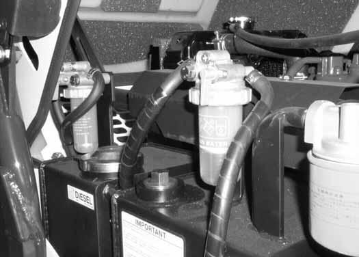
Remove the fuel cap (Item 1) [Figure 10-80-1] at the right side of the engine compartment.
Use a clean, approved safety container to add fuel. Add fuel only in an area that has a free movement of air and no flames or sparks. NO SMOKING!
Install and tighten the fuel fill cap. Close the engine cover.
Remove the water trap (Item 1) [Figure 10-80-2]. Empty the water, clean and install the container. Hand tighten the nut.
Replacing The Fuel Filter
Remove the filter housing (Item 2) [Figure 10-80-2] Remove and discard the filter.
316 Excavator 10-80-1Service Manual
Figure 10-80-1
W-2063-0887
W-2103-1285
Figure 10-80-2
TEMP. F° (C° ) NO. 2 NO. 1 +15° (9° )100%0% Down to -20° (-29° )50%50% Below -20° (-29° )0%100%
1
P-59195
1 2
P-59196
Clean the filter housing and the area around the filter head. Install a new fuel filter element and hand tighten the nut.

FUEL SYSTEM (CONT’D)
Draining The Fuel Tank
See SERVICE SCHEDULE on Page 10-50-1, for the correct service interval.
Turn the upperstructure 90 degrees counterclockwise to align the drain between the tracks.
Dispose of the fuel in an environmentally safe manner.
Removing Air From The Fuel System
After replacing the fuel filter or when the fuel tank has run out of fuel, air must be removed from the fuel system before starting the engine.
WARNING
Diesel fuel or hydraulic fluid under pressure can penetrate skin or eyes, causing serious injury or death. Fluid leaks under pressure may not be visible. Use a piece of cardboard or wood to find leaks. Do not use your bare hand. Wear safety goggles. If fluid enters skin or eyes, get immediate medical attention from a physician familiar with this injury.
316 Excavator 10-80-2Service Manual
Figure 10-80-3
Remove the drain plug (Item 1) [Figure 10-80-3] from the bottom of the fuel tank and let the fuel drain into a container.
1
W-2072-0496 P-43548
Open the engine cover.
Open the valve (Item 1) [Figure 10-80-4]
Close the engine cover.
Turn the key to the START position and run the starter for 3 to 6 seconds.
NOTE: If the engine starts, turn the key off immediately.
Open the engine cover and close the valve (Item 1) [Figure 10-80-4]

Close the engine cover.
Turn the key to START and release the key when the engine starts.
IMPORTANT
Do not engage the starter for longer than 30 seconds at a time. Longer use can damage the starter by overheating. Cool the starter for one minute between uses.
I-2209-0301
Repeat the procedure as needed until the engine starts.
316 Excavator 10-80-3Service Manual
Figure 10-80-4
1
P-59197
ENGINE LUBRICATION SYSTEM
Checking Engine Oil
Check the engine oil every day before starting the engine for the work shift.
Open the engine cover. (See Opening the Engine Cover on Page 10-40-1.)
Replacing Oil And Filter
See SERVICE SCHEDULE on Page 10-50-1, for the service interval.
Run the engine until it is at operating temperature. Stop the engine.

Open the engine cover. (See Opening the Engine Cover on Page 10-40-1.)
Remove the dipstick (Item 1) [Figure 10-90-1]. Keep the oil level between the marks on the dipstick.
Use a good quality motor oil that meets the correct API Service Classification. (See UPPERSTRUCTURE SLEW LOCK on Page 10-20-1.)
Remove the drain plug (Item 1) [Figure 10-90-2]. Drain the oil into a container.
Recycle or dispose of used oil in an environmentally safe manner.

316 Excavator 10-90-1Service Manual
Figure 10-90-1
Figure 10-90-2
1 2
P-59197
P-43546
1
ENGINE LUBRICATION SYSTEM (CONT’D)

Replacing Oil And Filter (Cont’d)
Figure 10-90-3
Remove the oil filter (Item 1) [Figure 10-90-3] and clean the oil filter housing.
Use a genuine Bobcat replacement filter. Put clean oil on the filter gasket, install the filter and hand tighten.
Install and tighten the oil drain plug.
Remove the fill cap (Item 2) [Figure 10-90-1] and put 3.4 qt. (3.3 L) of oil into the engine. (See FUEL, COOLANT AND LUBRICANTS on Page SPEC-60-1)
Install the fill cap.
Start the engine and let run for several minutes.
Stop the engine and check for leaks at the oil filter. Check the oil level. Add oil as needed if it is not at the top mark on the dipstick.
316 Excavator 10-90-2Service Manual
1
P-39951
HYDRAULIC SYSTEM Checking And Adding Fluid

Put the machine on a level surface.
Retract the arm and bucket cylinders, put the bucket on the ground and raise the blade. Stop the engine.
Raise the engine cover.
Figure 10-100-1
Check the fluid level in the sight gauge (Item 1) [Figure 10-100-1]. The level must be at the center of the sight gauge.
Remove the fill cap (Item 2) [Figure 10-100-1] and add fluid as needed.
Install the fill cap and lower the engine cover.
WARNING
Always clean up spilled fuel or oil. Keep heat, flames, sparks or lighted tobacco away from fuel and oil. Failure to use care around combustibles can cause explosion or fire which can result in injury or death.
W-2103-1285
Replacing The Hydraulic Filter
See SERVICE SCHEDULE on Page 10-50-1 for the correct service interval.
Raise the engine cover.
Figure 10-100-2
Remove the filter (Item 1) [Figure 10-100-2]
Clean the filter housing where the filter gasket makes contact.
Put clean hydraulic fluid on the gasket. Install the new filter and hand tighten only.
Start the engine and run the excavator through the hydraulic functions. Stop the engine. Check the fluid level at the sight gauge and add fluid as needed. Check the filter area for leaks.
316 Excavator 10-100-1Service Manual
1 2
P-59200
1 2 3
P-59200
HYDRAULIC SYSTEM (CONT’D)
Replacing The Hydraulic Fluid
See SERVICE SCHEDULE on Page 10-50-1, for the correct service interval.
Retract the arm and bucket cylinders. lower the bucket to the ground. Stop the engine.
Remove and replace the hydraulic filter.
Remove the fill cap [Figure 10-100-2 on Page 10-100-1] then remove the drain/filter cover (Item 1) [Figure 10100-3] from the bottom of the reservoir.
Drain the fluid into a container. Recycle or dispose of the used fluid in an environmentally safe manner.
Clean the filter.
Install the drain / filter cover (Item 1) [Figure 10-100-3].
Add fluid to reservoir (Item 2) [Figure 10-100-2 on Page 10-100-1] until it is at the center of the sight gauge (Item 3) [Figure 10-100-2 on Page 10-100-1] (See FUEL, COOLANT AND LUBRICANTS on Page SPEC-60-1) for type and capacity.
Start the engine and run the excavator through the hydraulic functions. Stop the engine. Check the fluid level at the sight gauge and add fluid as needed.
316 Excavator 10-100-2Service Manual
Figure 10-100-3
1
P-43548
LUBRICATING THE EXCAVATOR
Lubrication Locations
Lubricate the excavator as specified. (See SERVICE SCHEDULE on Page 10-50-1.)


Record the operating hours each time you lubricate the machine.


Always use a good quality lithium based multi-purpose grease when lubricating the machine. Apply the lubricant until extra grease shows.
Description (Number of Fittings)
316 Excavator 10-110-1Service Manual
Figure 10-110-1
Blade Cylinder - Rod End (1) (Item 1) [Figure 10-110-1]
Blade Cylinder - Base End (1) (Item 2) [Figure 10-110-1]
Figure 10-110-2
Boom Offset Cylinder - Rod End (1) (Item 3) [Figure 10110-2]
Boom Offset Cylinder - Base End (1) (Item 4) [Figure 10110-2]
1 2
P-39937
P-39957
4
P-39953
3
P-39954
LUBRICATING THE EXCAVATOR (CONT’D)


Lubrication Locations (Cont’d)
Figure 10-110-3
Boom Offset Pivot (2) (Item 5) [Figure 10-110-3]
Figure 10-110-4
Boom Cylinder - Rod End (1) (Item 6) [Figure 10-110-4]
Boom Cylinder - Base End (1) (Item 7) [Figure 10-110-4]
Arm Cylinder - Base End (1) (Item 8) [Figure 10-110-5]

Arm Cylinder- Rod End (1) (Item 9) [Figure 10-110-5]
Figure 10-110-6
Bucket Link Pivot (1) (Also lubricates rod end of bucket cylinder.) (Item 10) [Figure 10-110-6]
Bucket Pivots (2) (Item 11) [Figure 10-110-6]
316 Excavator 10-110-2Service Manual
Figure 10-110-5
5
P-43616
7 6
P-39938
8 9
P-39936
10 11 10
P-39934
LUBRICATING THE EXCAVATOR (CONT’D)
Lubrication Locations (Cont’d)
Figure 10-110-7
Swing Circle Pinion (1) (Item 12) [Figure 10-110-7]
Swing Circle Bearing (1) (Item 13) [Figure 10-110-7]
NOTE: Spread Lubriplate Gearshield Extra Heavy Grease evenly on wear surfaces on both sides of machine as required.

316 Excavator 10-110-3Service Manual
Figure 10-110-8
Track Expansion Tube, as required (4) (Item 14) [Figure 10-110-8]
12 13
P-43315
14
P-43719
TRAVEL MOTOR
Checking And Adding Oil
Figure 10-120-1
Put the machine on a level surface with the plugs positioned as shown (Item 1) [Figure 10-120-1]

Remove both plugs and add oil to the top hole until oil comes out of the lower hole.
Use sealing tape (EXAMPLE: Teflon Tape) on the threads and install both plugs.
Repeat for other side of machine.
Replacing Oil
Rotate the tracks so that one of the plugs is at the bottom, then remove both plugs.
Drain the oil into a container. Recycle or dispose of the oil in an environmentally safe manner.
After all the oil is removed, rotate the travel motor to the position shown [Figure 10-120-1]
Add oil to the top hole until oil comes out the lower hole. Install the plugs.
316 Excavator 10-120-1Service Manual
1
P-43552
ALTERNATOR BELT
Adjusting The Alternator Belt
Replace the belt if it has stretched or there are cracks in the belt. Replace the pulley if the belt contacts the bottom of the groove in the pulley.
Stop the engine.
Figure 10-130-1
Open the engine cover.
Loosen the mounting and adjustment bolts (Item 1) [Figure 10-130-1]
Move the alternator away from the engine to tighten the belt.
The tension is correct when there is 1/2 inch (13 mm) belt movement at the center of the belt span with 13 lbs. (18 N) of force.
Tighten the mounting and adjustment bolts (Item 1) [Figure 10-130-1]
Close the engine cover.
316 Excavator 10-130-1Service Manual
P-39951
1
SPARK ARRESTOR MUFFLER
See SERVICE SCHEDULE on Page 10-50-1, for the correct service interval.
Do not operate the excavator with a defective exhaust system.
Stop the engine and raise the engine cover.
Figure 10-140-1
WARNING
When an engine is running in an enclosed area, fresh air must be added to avoid concentration of exhaust fumes. If the engine is stationary, vent the exhaust outside. Exhaust fumes contain odorless, invisible gases which can kill without warning.
W-2050-1285
WARNING
Stop engine and allow the muffler to cool before cleaning the spark chamber. Wear safety goggles. Failure to obey can cause serious injury.
W-2011-1285
WARNING
Remove the plug (Item 1) [Figure 10-140-1]. from the bottom of the muffler.

Lower the engine cover, enter the excavator and fasten the seat belt.
Have a second person with safety goggles, hold an object over the outlet of the muffler.
Start the engine and run for about 10 seconds. The carbon deposits will be forced out of the muffler through the cleanout hole.
Stop the engine, raise the engine cover and install the plug.
Close the engine cover.
Never use machine in atmosphere with explosive dust or gases or where exhaust can contact flammable material. Failure to obey warnings can cause injury or death.
W-2068-1285
WARNING
When the engine is running during service, the steering levers must be in neutral.
Failure to do so can cause injury or death.
W-2203-0595
316 Excavator 10-140-1Service Manual
1
P-43554
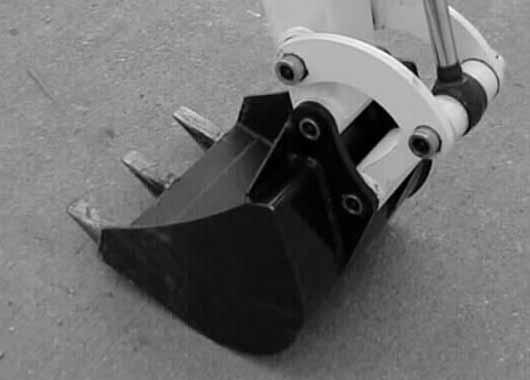
BLADE EXTENSION Installing And Removing
Put a block (Item 1) [Figure 10-150-1] under the blade. Fully lower the blade to the block and stop the engine.


Remove the extensions from the back side of the blade (Item 2) [Figure 10-150-1]
Use the same bolts to install the extensions on the ends of the blade [Figure 10-150-2]
When not using the extensions, always store them on the back side of the blade [Figure 10-150-1].
316 Excavator 10-150-1Service Manual
Figure 10-150-1
Figure 10-150-2
1 2
P-43578
P-43579
HYDRAULIC SYSTEM
316 Excavator 20-01Service Manual
ARM CYLINDER. . . . . . . . . . . . . . . . . . . . . . . . . . . . . . . . . . . 20-21-1 Assembly. . . . . . . . . . . . . . . . . . . . . . . . . . . . . . . . . . . . . 20-21-10 Checking The Arm Cylinder. . . . . . . . . . . . . . . . . . . . . . . . 20-21-1 Disassembly. . . . . . . . . . . . . . . . . . . . . . . . . . . . . . . . . . . . 20-21-6 Parts Identification. . . . . . . . . . . . . . . . . . . . . . . . . . . . . . . 20-21-5 Removal and Installation . . . . . . . . . . . . . . . . . . . . . . . . . . 20-21-3 AUXILIARY HYDRAULIC CONTROL VALVE. . . . . . . . . . . . 20-130-1 Disassembly And Assembly. . . . . . . . . . . . . . . . . . . . . . . 20-130-2 Removal And Installation. . . . . . . . . . . . . . . . . . . . . . . . . 20-130-1 BLADE CYLINDER. . . . . . . . . . . . . . . . . . . . . . . . . . . . . . . . . 20-24-1 Assembly. . . . . . . . . . . . . . . . . . . . . . . . . . . . . . . . . . . . . . 20-24-7 Checking The Blade Cylinder . . . . . . . . . . . . . . . . . . . . . . 20-24-1 Disassembly. . . . . . . . . . . . . . . . . . . . . . . . . . . . . . . . . . . . 20-24-4 Parts Identification. . . . . . . . . . . . . . . . . . . . . . . . . . . . . . . 20-24-3 Removal and Installation . . . . . . . . . . . . . . . . . . . . . . . . . . 20-24-2 BOOM CYLINDER . . . . . . . . . . . . . . . . . . . . . . . . . . . . . . . . . 20-20-1 Assembly. . . . . . . . . . . . . . . . . . . . . . . . . . . . . . . . . . . . . 20-20-13 Checking The Boom Cylinder . . . . . . . . . . . . . . . . . . . . . . 20-20-1 Disassembly. . . . . . . . . . . . . . . . . . . . . . . . . . . . . . . . . . . . 20-20-8 Parts Identification. . . . . . . . . . . . . . . . . . . . . . . . . . . . . . . 20-20-7 Removal and Installation . . . . . . . . . . . . . . . . . . . . . . . . . . 20-20-4 BOOM SWING CYLINDER. . . . . . . . . . . . . . . . . . . . . . . . . . . 20-22-1 Assembly. . . . . . . . . . . . . . . . . . . . . . . . . . . . . . . . . . . . . 20-22-10 Checking The Boom Swing Cylinder. . . . . . . . . . . . . . . . . 20-22-1 Disassembly. . . . . . . . . . . . . . . . . . . . . . . . . . . . . . . . . . . . 20-22-7 Parts Identification. . . . . . . . . . . . . . . . . . . . . . . . . . . . . . . 20-22-6 Removal and Installation . . . . . . . . . . . . . . . . . . . . . . . . . . 20-22-3 BUCKET CYLINDER. . . . . . . . . . . . . . . . . . . . . . . . . . . . . . . . 20-23-1 Assembly. . . . . . . . . . . . . . . . . . . . . . . . . . . . . . . . . . . . . 20-23-10 Checking The Bucket Cylinder. . . . . . . . . . . . . . . . . . . . . . 20-23-1 Disassembly. . . . . . . . . . . . . . . . . . . . . . . . . . . . . . . . . . . . 20-23-6 Parts Identification. . . . . . . . . . . . . . . . . . . . . . . . . . . . . . . 20-23-5 Removal and Installation . . . . . . . . . . . . . . . . . . . . . . . . . . 20-23-2 Continued On Next Page HYDRAULIC SYSTEM
316 Excavator 20-02Service Manual
HYDRAULIC CONTROL VALVE. . . . . . . . . . . . . . . . . . . . . . . 20-40-1 Boom And Arm Section . . . . . . . . . . . . . . . . . . . . . . . . . . . 20-40-8 Boom Swing Section . . . . . . . . . . . . . . . . . . . . . . . . . . . . 20-40-15 Disassembly And Assembly. . . . . . . . . . . . . . . . . . . . . . . . 20-40-5 Identification. . . . . . . . . . . . . . . . . . . . . . . . . . . . . . . . . . . . 20-40-4 Left Travel And Blade Section . . . . . . . . . . . . . . . . . . . . . 20-40-19 P1 And P2 Section. . . . . . . . . . . . . . . . . . . . . . . . . . . . . . . 20-40-7 Removal And Installation. . . . . . . . . . . . . . . . . . . . . . . . . . 20-40-1 Right Travel And Bucket Section. . . . . . . . . . . . . . . . . . . 20-40-23 Upperstructure Slew Section. . . . . . . . . . . . . . . . . . . . . . 20-40-12 HYDRAULIC FILTER MOUNT . . . . . . . . . . . . . . . . . . . . . . . 20-100-1 Removal And Installation. . . . . . . . . . . . . . . . . . . . . . . . . 20-100-1 HYDRAULIC PUMP . . . . . . . . . . . . . . . . . . . . . . . . . . . . . . . . 20-50-1 Assembly. . . . . . . . . . . . . . . . . . . . . . . . . . . . . . . . . . . . . . 20-50-9 Description. . . . . . . . . . . . . . . . . . . . . . . . . . . . . . . . . . . . . 20-50-1 Disassembly. . . . . . . . . . . . . . . . . . . . . . . . . . . . . . . . . . . . 20-50-5 Parts Identification. . . . . . . . . . . . . . . . . . . . . . . . . . . . . . . 20-50-4 Removal And Installation. . . . . . . . . . . . . . . . . . . . . . . . . . 20-50-3 Testing . . . . . . . . . . . . . . . . . . . . . . . . . . . . . . . . . . . . . . . . 20-50-1 HYDRAULIC RESERVOIR. . . . . . . . . . . . . . . . . . . . . . . . . . 20-110-1 Removal And Installation. . . . . . . . . . . . . . . . . . . . . . . . . 20-110-1 HYDRAULIC SYSTEM INFORMATION . . . . . . . . . . . . . . . . . 20-10-1 Troubleshooting Chart . . . . . . . . . . . . . . . . . . . . . . . . . . . . 20-10-1 ISO HYDRAULIC CONTROL CHANGE. . . . . . . . . . . . . . . . 20-121-1 ISO To Standard Control Pattern. . . . . . . . . . . . . . . . . . . 20-121-1 MAIN RELIEF VALVES. . . . . . . . . . . . . . . . . . . . . . . . . . . . . . 20-30-1 Testing And Adjusting The Main Relief Valves. . . . . . . . . . 20-30-1 PORT RELIEF VALVES . . . . . . . . . . . . . . . . . . . . . . . . . . . . . 20-31-1 Testing And Adjusting The Port Relief Valves . . . . . . . . . . 20-31-1 STANDARD HYDRAULIC CONTROL CHANGE . . . . . . . . . 20-120-1 Standard To ISO Control Pattern. . . . . . . . . . . . . . . . . . . 20-120-1 SWING MOTOR . . . . . . . . . . . . . . . . . . . . . . . . . . . . . . . . . . . 20-90-1 Assembly. . . . . . . . . . . . . . . . . . . . . . . . . . . . . . . . . . . . . 20-90-10 Disassembly. . . . . . . . . . . . . . . . . . . . . . . . . . . . . . . . . . . . 20-90-3 Parts Identification. . . . . . . . . . . . . . . . . . . . . . . . . . . . . . . 20-90-2 Removal And Installation. . . . . . . . . . . . . . . . . . . . . . . . . . 20-90-1 Continued On Next Page
HYDRAULIC SYSTEM (CONT’D)
Suggest:
If the above button click is invalid.
Please download this document first, and then click the above link to download the complete manual.
Thank you so much for reading

316 Excavator 20-03Service Manual HYDRAULIC
SWIVEL JOINT. . . . . . . . . . . . . . . . . . . . . . . . . . . . . . . . . . . . 20-80-1 Assembly. . . . . . . . . . . . . . . . . . . . . . . . . . . . . . . . . . . . . . 20-80-8 Disassembly. . . . . . . . . . . . . . . . . . . . . . . . . . . . . . . . . . . . 20-80-5 Parts Identification. . . . . . . . . . . . . . . . . . . . . . . . . . . . . . . 20-80-4 Removal And Installation. . . . . . . . . . . . . . . . . . . . . . . . . . 20-80-1 TRACK FRAME EXPANSION CYLINDER . . . . . . . . . . . . . . . 20-25-1 Assembly. . . . . . . . . . . . . . . . . . . . . . . . . . . . . . . . . . . . . 20-25-12 Checking The Track Frame Expansion Cylinder . . . . . . . . 20-25-1 Disassembly. . . . . . . . . . . . . . . . . . . . . . . . . . . . . . . . . . . . 20-25-9 Parts Identification. . . . . . . . . . . . . . . . . . . . . . . . . . . . . . . 20-25-8 Removal And Installation. . . . . . . . . . . . . . . . . . . . . . . . . . 20-25-2 TRACK FRAME EXPANSION VALVE. . . . . . . . . . . . . . . . . . . 20-60-1 Disassembly And Assembly. . . . . . . . . . . . . . . . . . . . . . . . 20-60-2 Removal And Installation. . . . . . . . . . . . . . . . . . . . . . . . . . 20-60-1 TRAVEL MOTOR . . . . . . . . . . . . . . . . . . . . . . . . . . . . . . . . . . 20-70-1 Assembly of Gear Unit. . . . . . . . . . . . . . . . . . . . . . . . . . . 20-70-16 Assembly of Motor Unit . . . . . . . . . . . . . . . . . . . . . . . . . . . 20-70-8 Disassembly of Gear Unit . . . . . . . . . . . . . . . . . . . . . . . . 20-70-13 Disassembly of Motor Unit. . . . . . . . . . . . . . . . . . . . . . . . . 20-70-4 Parts Identification. . . . . . . . . . . . . . . . . . . . . . . . . . . . . . . 20-70-3 Removal And Installation. . . . . . . . . . . . . . . . . . . . . . . . . . 20-70-1
SYSTEM (CONT’D)
HYDRAULIC SCHEMATIC
(ISO Control Pattern)
316 (S/N 522811001 AND ABOVE) (S/N 522911001 AND ABOVE)
(PRINTED JANUARY 2006)
V-0259legend
LEGEND
HYDRAULIC PUMP (2):
(P1) Gear Type . . . .. 2.7 GPM (10,2 L/min.) at 2300 RPM
RELIEF/ANTI-CAVITATION VALVE (2): 2774 PSI (191 bar)
RELIEF VALVE (2): 996 PSI (69 bar)
(P2) Gear Type . . . .. 2.7 GPM (10,2 L/min.) at 2300 RPM SHUTTLE VALVE
NOTE: Unless otherwise specified springs have NO significant pressure value.
V-0259legend (12-19-05)
Capacity . . . . . . . . . 13.7
L) 1 2 3
RESERVOIR With 100 mesh Suction Filter:
qt. (13
4 RELIEF VALVE: 2350 PSI (162 bar)
FIXED CAPACITY DISPLACEMENT BIDIRECTIONAL HYDRAULIC MOTOR 7 Printed in U.S.A. 5 6 FILTER
FILTER
8 9
(10 micron) -With SPRING LOADED
BYPASS VALVE: 21 PSI (1,5 bar)
DRIVE MOTOR SHUTTLE VALVE 10 LOAD CHECK VALVE