


Instructions are necessary before operating or servicing machine. Read and understand the Operation & Maintenance Manual, Operator’s Handbook and signs (decals) on machine. Follow warnings and instructions in the manuals when making repairs, adjustments or servicing. Check for correct function after adjustments, repairs or service. Untrained operators and failure to follow instructions can cause injury or death.
W-2003-0807
Safety Alert Symbol: This symbol with a warning statement, means: “Warning, be alert! Your safety is involved!” Carefully read the message that follows.

Never service the Bobcat SkidSteer Loader without instructions.
Use the correct procedure to lift or lower operator cab.
Have good ventilation when welding or grinding painted parts.
Wear dust mask when grinding painted parts. Toxic dust and gas can be produced. Avoid exhaust fume leaks which can kill without warning. Exhaust system must be tightly sealed.
Disconnecting or loosening any hydraulic tubeline, hose, fitting, component or a part failure can cause lift arms to drop. Do not go under lift arms when raised unless supported by an approved lift arm support device. Replace it if damaged.
Stop, cool and clean engine of flammable materials before checking fluids.
Never service or adjust loader with the engine running unless instructed to do so in the manual.
Avoid contact with leaking hydraulic fluid or diesel fuel under pressure. It can penetrate the skin or eyes.
Never fill fuel tank with engine running, while smoking or when near open flame.
Keep body, jewelry and clothing away from moving parts, electrical contact, hot parts and exhaust.
Wear eye protection to guard from battery acid, compressed springs, fluids under pressure and flying debris when engines are running or tools are used. Use eye protection approved for type of welding. Keep rear door closed except for service. Close and latch door before operating the loader.
Never work on loader with lift arms up unless lift arms are held by an approved lift arm support device. Replace if damaged. Never modify equipment or add attachments not approved by Bobcat Company.
WRONG B-6589
Lead-acid batteries produce flammable and explosive gases. Keep arcs, sparks, flames and lighted tobacco away from batteries. Batteries contain acid which burns eyes or skin on contact. Wear protective clothing. If acid contacts body, flush well with water. For eye contact flush well and get immediate medical attention.
Maintenance procedures which are given in the Operation & Maintenance Manual can be performed by the owner/ operator without any specific technical training. Maintenance procedures which are not in the Operation & Maintenance Manual must be performed ONLY BY QUALIFIED BOBCAT SERVICE PERSONNEL. Always use genuine Bobcat replacement parts. The Service Safety Training Course is available from your Bobcat dealer.
Cleaning and maintenance are required daily. MSW08-0409
This manual is for the Bobcat loader mechanic. It provides necessary servicing and adjustment procedures for the Bobcat loader and its component parts and systems. Refer to the Operation & Maintenance Manual for operating instructions, starting procedure, daily checks, etc.
A general inspection of the following items must be made after the loader has had service or repair:
1.Check that the ROPS/FOPS (Including side screens) is in good condition and is not modified.
2.Check that ROPS mounting hardware is tightened and is Bobcat approved.
9.The parking brake must function correctly.
10.Enclosure door latches must open and close freely.
3.The seat belt must be correctly installed, functional and in good condition.

4.The seat bar must be correctly adjusted, clean and lubricated.
11.Bob-Tach® wedges and linkages must function correctly and be in good condition.
12.Safety treads must be in good condition.
5.Check lift arm support device, replace if damaged.
13.Check for correct function of indicator lamps.
6.Machine signs (decals) must be legible and in the correct location.
14.Check all machine fluid levels.
7.Steering levers, hand controls and foot pedals must return to neutral (as applicable).
15.Inspect for fuel, oil or hydraulic fluid leaks.
8.Check for correct function of the work lights.
16.Lubricate the loader.
17.Check the condition of the battery and cables.
23.Operate the machine and check all functions.
18.Inspect the air cleaner for damage or leaks. Check the condition of the element.
24.Check for correct function of the Bobcat Interlock Control System (BICS™) before the machine is returned to the customer.
19.Check the electrical charging system.
25.Check for proper function of front horn and back-up alarm (if equipped).
20.Check tires for wear and pressure. Check tracks for wear and tension. Use only approved tires or tracks.
21.Inspect for loose or broken parts or connections.
26.Check function or condition of all equipped options and accessories (examples: fire extinguisher, rotating beacon, lift kits, etc.).

27.Recommend to the owner that all necessary corrections be made before the machine is returned to service.
22.Check for any field modification not completed.
Diesel engine exhaust and some of its constituents are known to the state of California to cause cancer, birth defects and other reproductive harm.
This symbol with a warning statement means: “Warning, be alert! Your safety is involved!” Carefully read the message that follows.
AVOID INJURY OR DEATH
Instructions are necessary before operating or servicing machine. Read and understand the Operation & Maintenance Manual, Operator’s Handbook and signs (decals) on machine. Follow warnings and instructions in the manuals when making repairs, adjustments or servicing. Check for correct function after adjustments, repairs or service. Untrained operators and failure to follow instructions can cause injury or death.
W-2003-0807
This notice identifies procedures which must be followed to avoid damage to the machine.
I-2019-0284
The signal word DANGER on the machine and in the manuals indicates a hazardous situation which, if not avoided, will result in death or serious injury.
D-1002-1107
The signal word WARNING on the machine and in the manuals indicates a potentially hazardous situation which, if not avoided, could result in death or serious injury.
W-2044-1107
The following publications provide information on the safe use and maintenance of the Bobcat machine and attachments:
•The Delivery Report is used to assure that complete instructions have been given to the new owner and that the machine is in safe operating condition.
•The Operation & Maintenance Manual delivered with the machine or attachment contains operating information as well as routine maintenance and service procedures. It is a part of the machine and can be stored in a container provided on the machine. Replacement Operation & Maintenance Manuals can be ordered from your Bobcat dealer.
•Machine signs (decals) instruct on the safe operation and care of your Bobcat machine or attachment. The signs and their locations are shown in the Operation & Maintenance Manual. Replacement signs are available from your Bobcat dealer.
•An Operator’s Handbook fastened to the operator cab. It’s brief instructions are convenient to the operator. The handbook is available from your dealer in an English edition or one of many other languages. See your Bobcat dealer for more information on translated versions.
•The AEM Safety Manual delivered with the machine gives general safety information.
•The Service Manual and Parts Manual are available from your dealer for use by mechanics to do shoptype service and repair work.
•The Skid-Steer Loader Operator Training Course is available through your local dealer or at bobcat.com/ training or bobcat.com. This course is intended to provide rules and practices of correct operation of the skid-steer loader. The course is available in English and Spanish versions.
•Service Safety Training Courses are available from your Bobcat dealer or at bobcat.com/training or bobcat.com. They provide information for safe and correct service procedures.
•The Skid-Steer Loader Safety Video is available from your Bobcat dealer or at bobcat.com/training or bobcat.com
The machine and some attachments have components that are at high temperatures under normal operating conditions. The primary source of high temperatures is the engine and exhaust system. The electrical system, if damaged or incorrectly maintained, can be a source of arcs or sparks.
Flammable debris (leaves, straw, etc.) must be removed regularly. If flammable debris is allowed to accumulate, it can cause a fire hazard. Clean often to avoid this accumulation. Flammable debris in the engine compartment is a potential fire hazard.
The operator’s area, engine compartment and engine cooling system must be inspected every day and cleaned if necessary to prevent fire hazards and overheating.
All fuels, most lubricants and some coolants mixtures are flammable. Flammable fluids that are leaking or spilled onto hot surfaces or onto electrical components can cause a fire.
Do not use the machine where exhaust, arcs, sparks or hot components can contact flammable material, explosive dust or gases.
Check hydraulic tubes, hoses and fittings for damage and leakage. Never use open flame or bare skin to check for leaks. Hydraulic tubes and hoses must be properly routed and have adequate support and secure clamps. Tighten or replace any parts that show leakage.
Always clean fluid spills. Do not use gasoline or diesel fuel for cleaning parts. Use commercial nonflammable solvents.
Check all electrical wiring and connections for damage. Keep the battery terminals clean and tight. Repair or replace any damaged part or wires that are loose or frayed.
Battery gas can explode and cause serious injury. Use the procedure in the Operation & Maintenance Manual for connecting the battery and for jump starting. Do not jump start or charge a frozen or damaged battery. Keep any open flames or sparks away from batteries. Do not smoke in battery charging area.
Stop the engine and let it cool before adding fuel. No smoking! Do not refuel a machine near open flames or sparks. Fill the fuel tank outdoors.
Ultra Low Sulfur Diesel (ULSD) poses a greater static ignition hazard than earlier diesel formulations with higher Sulfur content. Avoid death or serious injury from fire or explosion. Consult with your fuel or fuel system supplier to ensure the delivery system is in compliance with fueling standards for proper grounding and bonding practices.
Starting
Do not use ether or starting fluids on any engine that has glow plugs or air intake heater. These starting aids can cause explosion and injure you or bystanders.

Use the procedure in the Operation & Maintenance Manual for connecting the battery and for jump starting.
The spark arrester exhaust system is designed to control the emission of hot particles from the engine and exhaust system, but the muffler and the exhaust gases are still hot.
Check the spark arrester exhaust system regularly to make sure it is maintained and working properly. Use the procedure in the Operation & Maintenance Manual for cleaning the spark arrester muffler (if equipped).
Always clean the machine and attachment, disconnect the battery, and disconnect the wiring from the Bobcat controllers before welding. Cover rubber hoses, battery and all other flammable parts. Keep a fire extinguisher near the machine when welding.
Have good ventilation when grinding or welding painted parts. Wear dust mask when grinding painted parts. Toxic dust or gas can be produced.
Dust generated from repairing nonmetallic parts such as hoods, fenders or covers can be flammable or explosive. Repair such components in a well ventilated area away from open flames or sparks.
Know where fire extinguishers and first aid kits are located and how to use them. Inspect the fire extinguisher and service the fire extinguisher regularly. Obey the recommendations on the instructions plate.
Always use the serial number of the loader when requesting service information or when ordering parts. Early or later models (identification made by serial number) can use different parts, or it can be necessary to use a different procedure in doing a specific service operation.
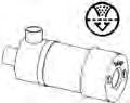
Engine Serial Number
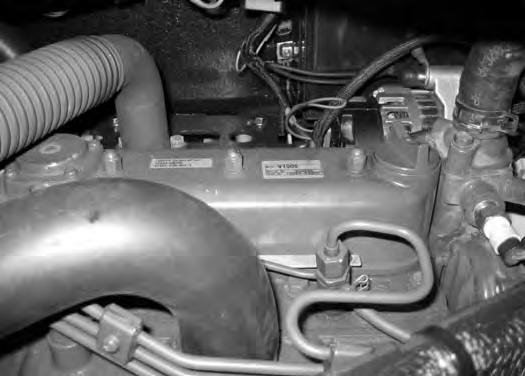
The loader serial number plate (Item 1) [Figure 1] is located inside the cab on the right-hand side.
XXXX XXXXX

The delivery report [Figure 3] contains a list of items that must be explained or shown to the owner or operator by the dealer when the Bobcat loader is delivered.
The delivery report must be reviewed and signed by the owner or operator and the dealer.
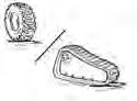
[A] Bucket – Several different buckets and other attachments are available for the Bobcat loader.
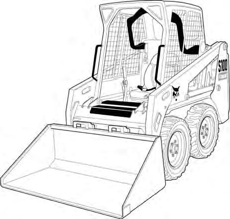
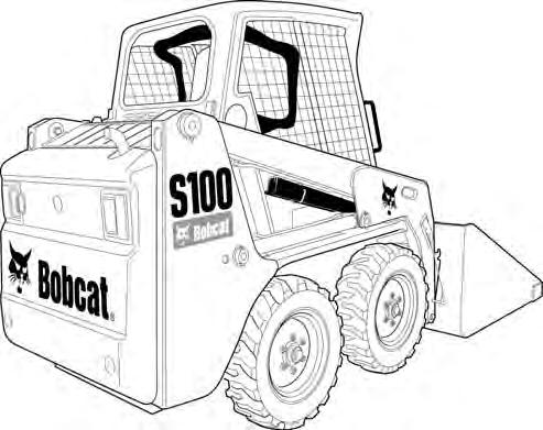
[B] ROPS – Roll-Over Protective Structure per ISO 3471 and FOPS – Falling-Object Protective Structure per ISO 3449, Level I. Level II is available.
3.Tires – Standard tires are shown. Several different tire styles and sizes are available for the Bobcat loader.
LIFTING AND BLOCKING THE LOADER
Procedure
Figure 10-10-1
AVOID INJURY OR DEATH
Instructions are necessary before operating or servicing machine. Read and understand the Operation & Maintenance Manual, Operator’s Handbook and signs (decals) on machine. Follow warnings and instructions in the manuals when making repairs, adjustments or servicing. Check for correct function after adjustments, repairs or service. Untrained operators and failure to follow instructions can cause injury or death.
W-2003-0807
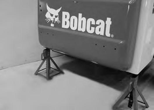
Always park the loader on a level surface.
Put jackstands under the front axles and rear corners of the frame before running the engine for service. Failure to use jackstands can allow the machine to fall or move and cause injury or death.
W-2017-0286
Figure 10-10-2
S6030
Put the floor jack under the rear of the loader [Figure 1010-2]
Lift the rear of the loader and install jackstands [Figure 10-10-2].
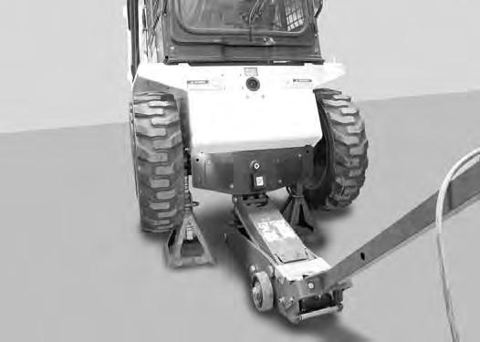
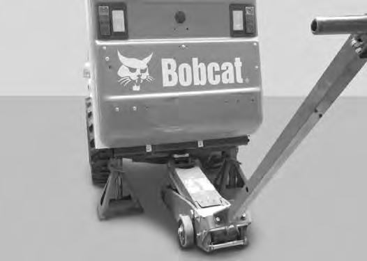
Figure 10-10-3
S6031
Put the floor jack under the front of the loader [Figure 1010-3].
Lift the front of the loader and put jackstands under the axle tubes [Figure 10-10-3]
NOTE:Make sure the jackstands do not touch the tires. Make sure tires clear floor or any obstacles.
Installing
Maintenance and service work can be done with the lift arms lowered. If the lift arms are raised, use the following procedures to engage and disengage an approved lift arm support device.
Never work on a machine with the lift arms up unless the lift arms are secured by an approved lift arm support device. Failure to use an approved lift arm support device can allow the lift arms or attachment to fall and cause injury or death.
Service lift arm support device if damaged or if parts are missing. Using a damaged lift arm support or with missing parts can cause lift arms to drop causing injury or death.
AVOID DEATH
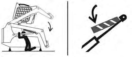
•Disconnecting or loosening any hydraulic tubeline, hose, fitting, component or a part failure can cause lift arms to drop.
•Keep out of this area when lift arms are raised unless supported by an approved lift arm support. Replace if damaged.
D-1009-0409
Remove attachment from the loader.
Before the cab or the lift arms are raised for service, jackstands must be put under the rear corners of the frame. Failure to use jackstands can allow the machine to tip backward causing injury or death.
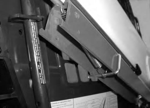
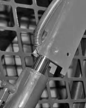
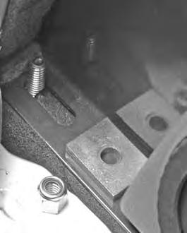
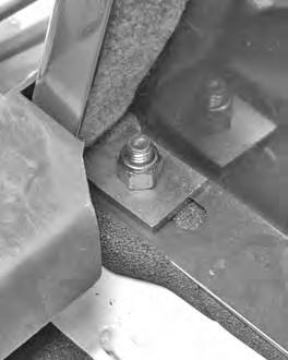
Disconnect the spring (Item 1) from the lift arm support device retaining pin. Support the lift arm support device (Item 2) with your hand and remove the retaining pin (Item 3) [Figure 10-20-2]
Installing (Cont’d)
Figure 10-20-3
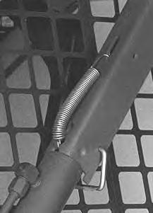
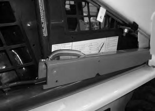
Lower the lift arm support device to the top of the lift cylinder. Hook the free end of the spring (Item 1) [Figure 10-20-3] to the lift arm support device so the spring does not interfere with the support device engagement.
Sit in the operator seat, fasten the seat belt and lower the seat bar. Start the engine.
Figure 10-20-4
Raise the lift arms until the lift arm support device drops onto the lift cylinder rod (Item 1) [Figure 10-20-4]
Lower the lift arms slowly until the support device is held between the lift arm and the lift cylinder. Stop the engine.
Raise the seat bar, disconnect the seat belt and move the pedals until both lock.
Install the retaining pin (Item 2) [Figure 10-20-4] into the rear of the lift arm support device below the cylinder rod.

Remove the retaining pin (Item 1) [Figure 10-20-4] from the lift arm support device.
Figure 10-20-5
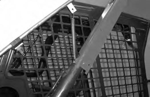
Connect the spring (Item 1) [Figure 10-20-5] from the lift arm support device to the bracket below the lift arms.
Sit in the operator’s seat, fasten the seat belt and lower the seat bar. Start the engine.
Figure 10-20-6
Raise the lift arms a small amount. The spring will lift the support device off the lift cylinder rod. Lower the lift arms. Stop the engine.
Raise the seat bar, unbuckle the seat belt, move the pedals until both lock and exit the cab.
Disconnect the spring from the bracket.
Raise the support device into storage position and insert the retaining pin (Item 1) [Figure 10-20-6] through the lift arm support device and through the bracket. Connect the spring to the retaining pin.
Remove the jackstands.
Suggest:
If the above button click is invalid.
Please download this document first, and then click the above link to download the complete manual.
Thank you so much for reading

The Bobcat loader has an operator cab (ROPS and FOPS) as standard equipment to protect the operator from rollover and falling objects. The seat belt must be worn for rollover protection. Check the cab, mounting, and hardware for damage. Never modify the cab. Replace the cab and hardware if damaged.
ROPS - Roll-Over Protective Structure per ISO 3471 and FOPS - Falling-Object Protective Structure per ISO 3449, Level I. Level II is available.
Level I - Protection from falling bricks, small concrete blocks, and hand tools encountered in operations such as highway maintenance, landscaping, and other construction sites.
Level II - Protection from falling trees, rocks: for machines involved in site clearing, overhead demolition or forestry.
Never modify operator cab by welding, grinding, drilling holes or adding attachments unless instructed to do so by Bobcat Company. Changes to the cab can cause loss of operator protection from rollover and falling objects, and result in injury or death.
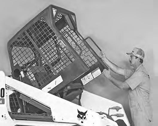
Always stop the engine before raising or lowering the cab.
Stop the loader on a level surface and lower the lift arms. If the lift arms must be up while raising the operator cab, install the lift arm support device. (See LIFT ARM SUPPORT DEVICE on Page 10-20-1.)
Before the cab or the lift arms are raised for service, jackstands must be put under the rear corners of the frame. Failure to use jackstands can allow the machine to tip backward causing injury or death.
P-90328
•Disconnecting or loosening any hydraulic tubeline, hose, fitting, component or a part failure can cause lift arms to drop.
•Keep out of this area when lift arms are raised unless supported by an approved lift arm support. Replace if damaged.
D-1009-0409
Raising (Cont’d)
Remove
NOTE: