
KEVIN CRUMLEY
PORTFOLIO

 Professional
Academic
Fabricated
Professional
Academic
Fabricated
LAW ON BROAD STREET Charleston, SC DOGTROT CABIN Georgetown, SC CAMERON TRAIN DEPOT Cameron, SC birdBOX South Carolina Botanical Garden WEST ASHLEY BRIDGE Charleston, SC SILVER FLAG HEADQUARTERS Tyndall Air Force Base, FL THE REVITALIZATION OF CASTELLETTO Genoa, Italy CINEMA HOUSE Los Angeles, CA INVASION OF CHARLESTON Charleston, SC 4 8 14 FABRICATED PROFESSIONAL ACADEMIC 18 22 28 34 42 48 CONTENTS
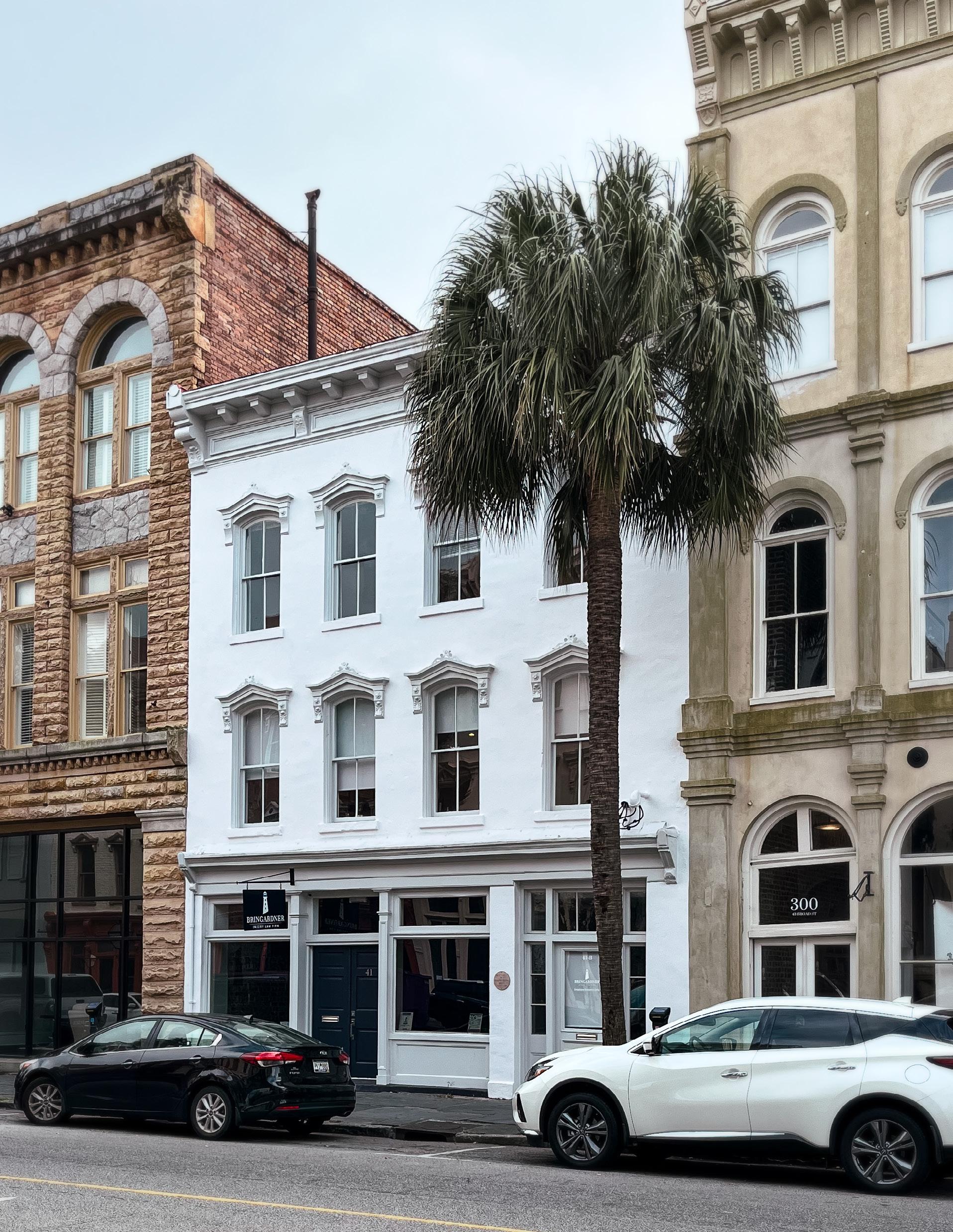
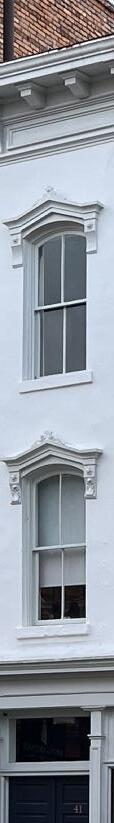
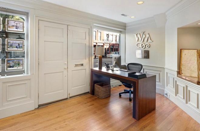
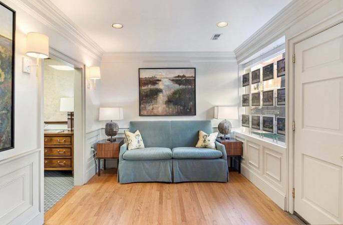
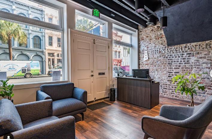
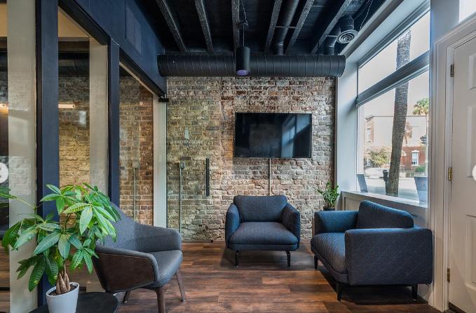
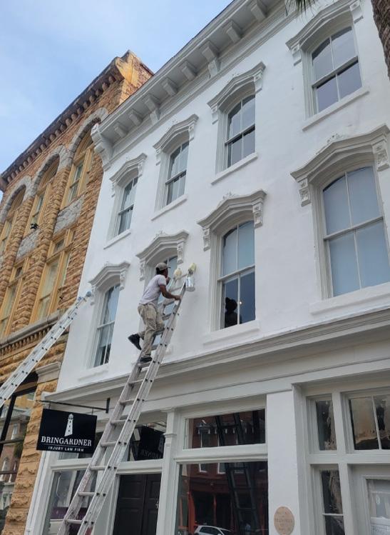
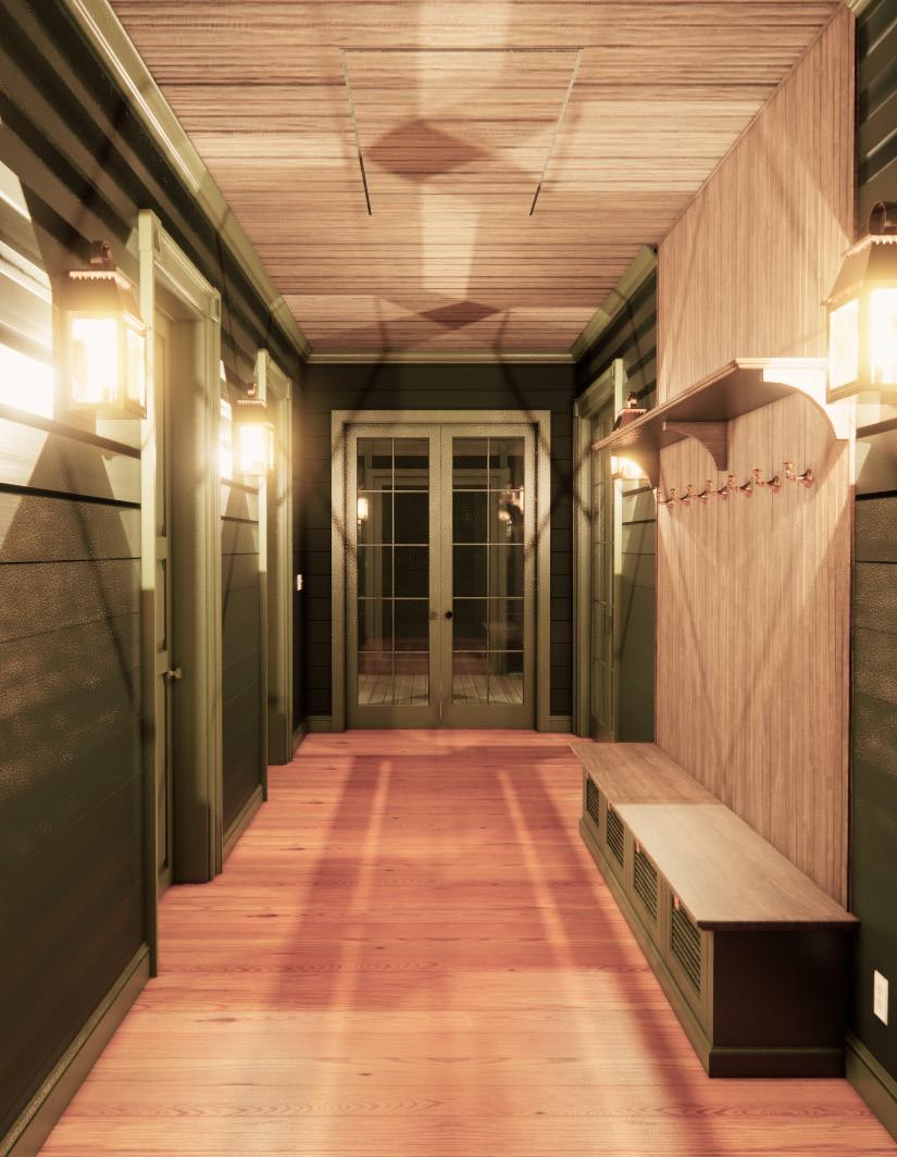
LAW ON BROAD STREET
Charleston, SC
Originally constructed in 1835 by William Waller, 41 Broad Street is located in the Charleston Historic District. As a first-floor renovation to a law office, our client at Broad Street requested a modern office space with exceptional quality of light. After a 3D scan and exploration into the makeup of the existing walls, we presented a scheme that included exposing the original brick and stucco and adding a series of glass partitions for meeting rooms. We also recovered the exterior transom windows facing Broad Street. During the demo, we uncovered a large, make-shift beam in the rear ceiling, supporting a rear addition. This made moving forward a careful and precise business, requiring an adjustment to the original layout to fit all of the required program.
Completed: 2023
Architect: Synchronicity Land + Architecture
GC: Dominick & Co.
Select Photos: Tyler Davidson & Pate Dominick -Charleston BAR-S Public Meeting Link: https://www.youtube.com/ watch?v=Q_vA0YxZvPk
5
First floor plan

PROPOSED FIRST FLOOR
First floor demo plan
EXISTING FIRST FLOOR PLAN
6 102 HALL 109 BATH DEMO EXISTING WALL DEMO TO EXPOSE BRICK DEMO TO BRICK DEMO TO BRICK DEMO TO STUCCO AND BRICK DEMO EXISTING WALL DEMO EXISTING MECH. ROOM DEMO EXISTING BATHROOM DEMO TO BRICK DEMO EXISTING WALL DEMO EXISTING WALL DEMO EXISTING WALL DEMO EXISTING WALL DEMO FOR ADA COMPLIANT RAMP DEMO EXISTING WALL DEMO EXISTING WALL DEMO EXISTING DOOR DEMO TO BRICK DEMO TO EXISTING BRICK FIREPLACE DEMO EXISTING WALL DEMO TO BRICK DEMO TO BRICK DEMO EXISTING WALL DEMO EXISTING DOOR DEMO EXISTING DOOR DEMO TO BRICK DEMO EXISTING DOOR 110 MECH 104 OFFICE 103 OFFICE 105 ROOM 106 ROOM 107 ROOM 101 FOYER 111 ROOM 112 ROOM 108 HALL UP DEMO TO STUCCO AND BRICK DEMO TO STUCCO AND BRICK DEMO TO STUCCO AND BRICK BASE 36" BASE 36" REF. 36" BASE 36" CAB BASE 38" UNDER COUNTER CAB BASE DN 6'' RAMP @ 1:12 SLOPE 105 OFFICE 104 SMALL CONFERENCE ROOM 103 LARGE CONFERENCE ROOM 107 BREAK ROOM 106 BATHROOM 108 MECH. 101 FOYER A A A DEMO TO EXPOSE EXISTING FIREPLACE A A A A A A A A B B B REESTABLISH GLASS TRANSOM OVER EXISTING DOOR & WINDOWS NEW LANDING & RAMP WITH MAX 6'' DROP, G.C. TO VERIFY IN FIELD B B 102 HALL 110 HALL EXISTING DOOR SWING TO BE REVERSED FOR EGRESS PER 2018 IBC, CHAPTER 10, AND 2017 ICC A117.1, SECTION 404.2.3 101 102 103 104 105 106 107 2'-11 1/2" 4'-4 1/2" 10" 5'-0" 1'-1 1/2" 1'-0 1/2" 2'-0" 1'-0" B 109 CLOSET 1'-7 1/4" 3" 2'-10" A 2" 3'-0" 7'-1 1/2" 3'-9 1/4'' 1'-10" 12'-11 1/2" 3'-8 1/2" 3'-0" 13'-7 3/4" UP 9'-11 1/4" 1 A-501 B 2'-8 1/2" 1'-8 1/2" 3'-0" A-701 3 D C B A
SCALE: 1/4"=1'-0" @ 24"x36" OR 1/8"=1'-0" @
1
SCALE: 1/4"=1'-0" @ 24"x36"
1/8"=1'-0"
OR
@ 2
Before
After
After Before
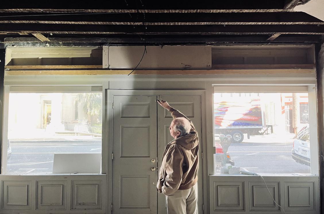
7 Site visit w/ our structural
engineer
Facade repair
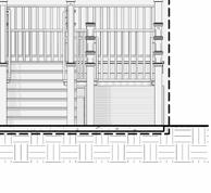
DOGTROT CABIN
Georgetown, SC
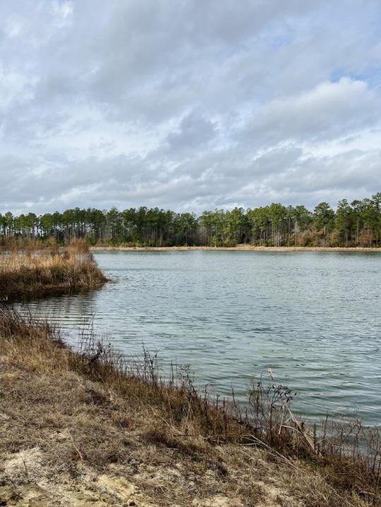
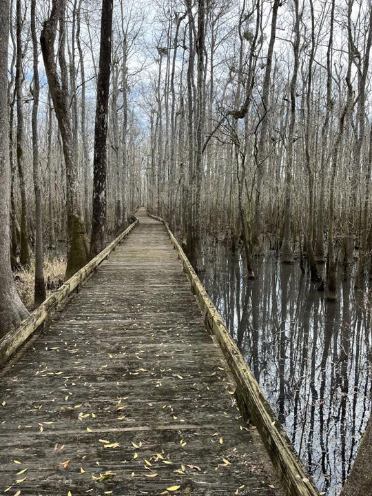
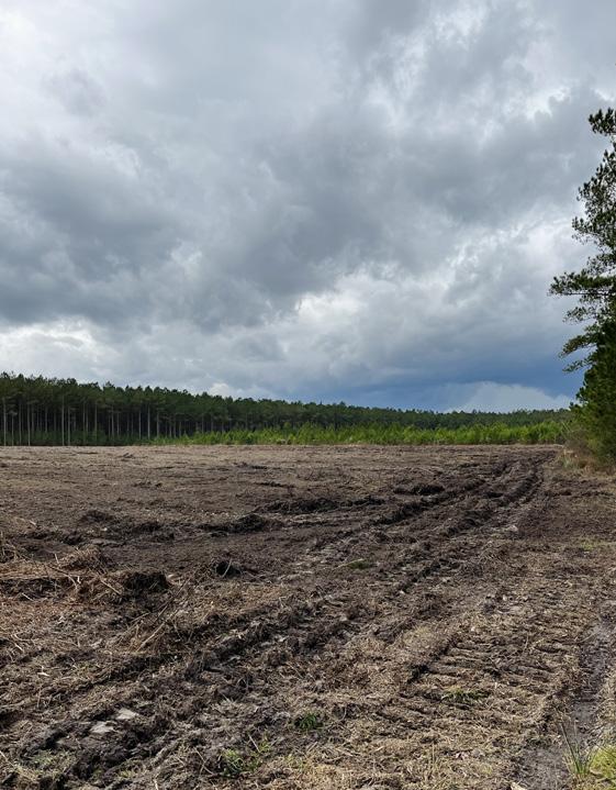
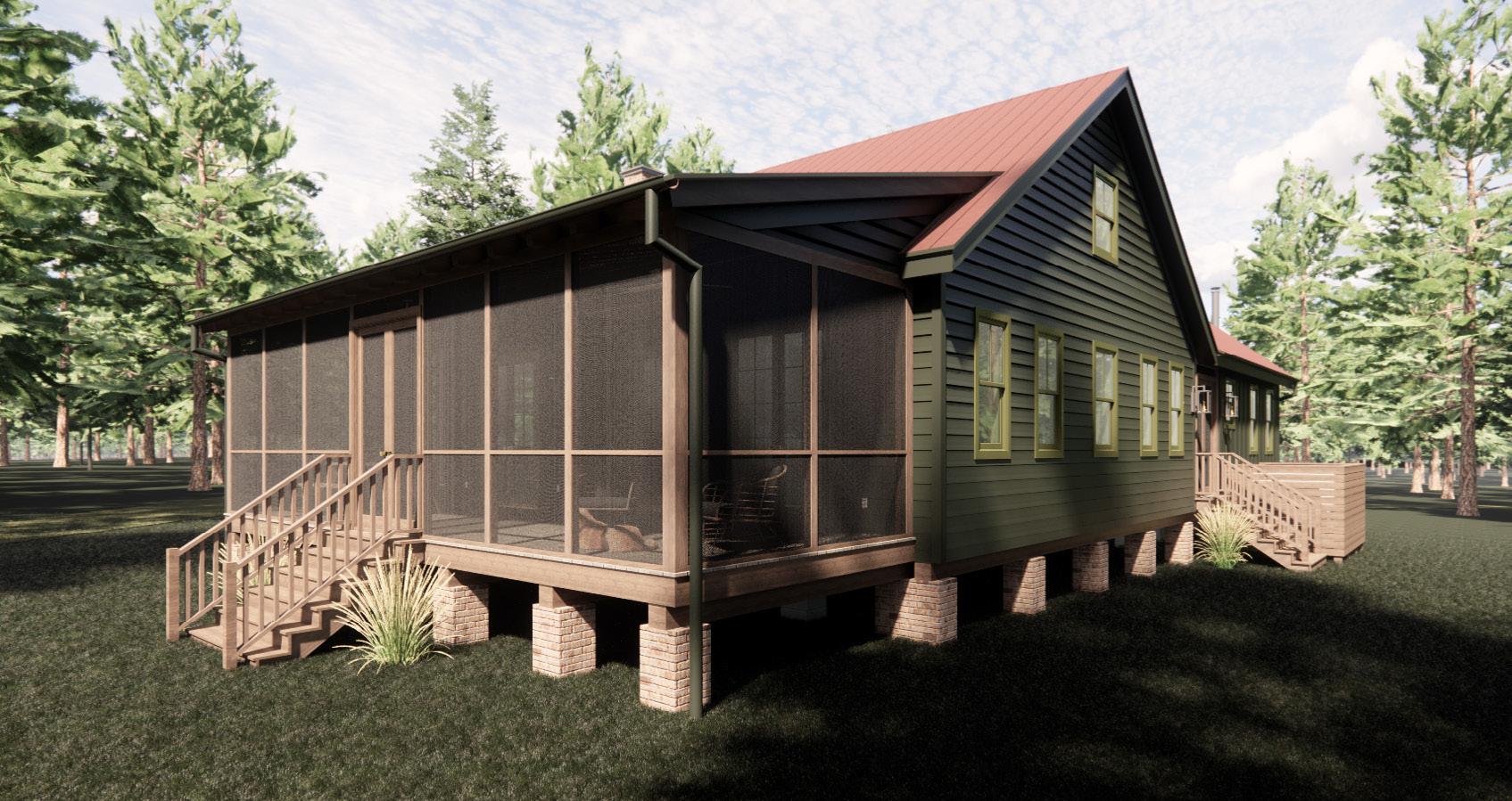
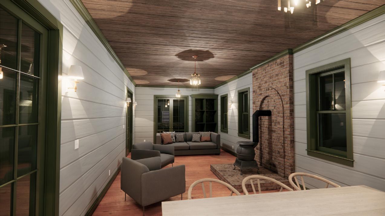
Located on nearly 400 acres adjacent to the Pee Dee River in Georgetown South Carolina, our client purchased the plot with the dream of building a traditional southern cabin in the middle of the woods. The cabin is designed to imitate the “Dogtrot” layout, which would originally have included an open breezeway through the center of the house. With a slightly modern interpretation of the layout, the Cabin is elevated 4 feet off the ground on brick piers and timber girders to provide a buffer from potential flash flooding. Three large doors on the front of the cabin accept the prevailing northwest winds, filtering them throughout the house. The great room is centered around a brick hearth and an antique potbelly stove for the occasional cold winter night. Then of course the central heating would kick on before the experience gets too chilly.
Under Construction
Architect: Meadors, Inc.
GC: Meadors, Inc.
9

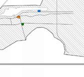
10 PINE STAND AVERAGE SIZE 12" 12"CPP OVERFLOW PIPE TOP =28.59' INV =30.91' INV=28.44' 6"12"L OAK 18"PINE 22"PINE 18"PINE 20"PINE 20"PINE 18"PINE 18"PINE 18"PINE 18"PINE 18"PINE 18"PINE 18"PINE 18"PINE 18"PINE 18"PINE 20"PINE 20"PINE 18"PINE 18"PINE 20"PINE 18"PINE 18"PINE 18"PINE 22"PINE 20"PINE 178 140 142 168 169 180 182 183 184 185 186 188 189 201 202 204 205 213 214 216 217 258 259 260 261 288 289 25 26 27 28 29 30 31 32 33 34 32 34 35 33 22 23 24 25 26 27 28 29 30 31 32 DITCH/SWALE LARGE POND TREE CLEARING EXTENTS SIGNIFICANT TREE TO REMAIN SIGNIFICANT TREE TO REMAIN GRAVEL CABIN ROAD SEPTIC DRAINFIELD SEPTIC REPAIR LINES 75' WELL SETBACK 75' WELL SETBACK 15' BUILDING SETBACK IRRIGATION WELL LOCATION IRRIGATION WELL PUMP LOCATION 1. 2. 3. 4. 5. GRADING AND SITEWORK TO BE MINIMAL IN ALL AREAS NOT DIRECTLY AFFECTED BY THE WORK. FOLLOW BEST PRACTICES AND LOCAL REQUIREMENTS IN ORDER TO MINIMIZE ENVIRONMENTAL DAMAGE. PLUMBING LINES, SANITARY SEWER LINES. STORM DRAINAGE LINES, DOMESTIC WATER LINES, GAS LINES, TELECOMMUNCATIONS CABLING, AND IRRIGATION LINES ARE TO BE INSTALLED ON A DESIGN-BUILD BASIS. FINISH GRADE MUST SLOPE AWAY FROM EXTERIOR FOUNDATION WALL, AT A HEIGHT OF 6 INCHES OVER A 10 FOOT DISTANCE. ANY SURVEY MARKERS WITHIN THE AREA OF CONSTRUCTION SHALL BE PRESERVED. IF A MARKER IS ALTERED BY A CONTRACTOR, IT SHALL BE RESET BY A REGISTERED CIVIL ENGINEER OR LICENSED LAND SURVEYOR AT THE COST OF THAT CONTRACTOR. BEFORE GRADING OPERATIONS, A TEMPORARY PROTECTION FENCE SHALL BE CONSTRUCTED AROUND ANY TREE WITHIN 30 FEET OF THE FOUNDATION, AND A SILT FENCE MUST BE CONSTRUCTED DOWNSLOPE OF ANY AREA WHERE THE SOIL IS DISTURBED. SITEWORK/GRADING NOTES SITEMAPSITEMAP HWY701 GREAT PEE DEE RIVER OLD PEE DEE RD DAWES 1. 2. CRITICAL ROOT ZONE RADIUS IS SHOWN AT 1' FOR EVERY 1'' AT TRUNK DIAMETER AT BREAST HEIGHT. ONLY SIGNIFICANT TREES ARE SHOWN IN SURVEY. GENERAL SITE PLAN NOTES 2811 AZALEA DRIVE CHARLESTON, SC 843.723.8585 PRINTED ON: FILE LOCATION: PROJ. NO. ISSUE DATE: SCALE SHOWN ON DRAWINGS IS ONLY CORRECT IF THIS SHEET IS PRINTED AT 24"X36" Architecture Construction Design Services Cabinetry Millwork Conservation Preservation Planning Estate Management 10/27/2023 12:49:08 PM C:\Users\Brittany Smith\Documents\Thompson DogtrotMain CabinCENTRAL MODEL_BrittanyCohen.rvt SITE PLANCABIN 22-0079 Thompson DogtrotCabin North Fraser St, Yauhanna, SC 29440 10/27/2023 PERMIT SET A012 1/16" = 1'-0" 1 00 - SITE PLAN - CABIN N - CABIN CHI TERED AR E IREG No. 9388 S SO OF UTH RO TECT CA TE STER C ED AR HI NA 100192 Charleston, SC T R S EGI ATEOF CTS SOUTH CAROLI MEADORS, INC. REVISIONS # DATE NOTES
site plan w/ septic and well locations
site photos
Cabin
Select
11 HB HB A301 A303 1 A303 A301 2 A302 402 SF FRONT PORCH 101 190 SF DOG TROT HALL 103 425 SF GREAT ROOM 102 318 SF REAR PORCH 107 141 SF BEDROOM 03 106 141 SF PRIMARY BEDROOM 104 179 SF KITCHEN 109 94 SF BEDROOM 02 105 70 SF BATH 108 WOOD FRAMED CHIMNEY W/ MASONRY VENEER FOR WOOD STOVE OUTDOOR SHOWER & HOSE BIB P.T. WOOD STAIR POTBELLY WOOD STOVE MASONRY HEARTH, 4'' A.F.F. HALLWAY BUILT-IN BENCH BLUESTONE HEARTH FLUSH WITH FLOOR SURFACE BUILT-IN WARDROBES A302 2 SCREENED P.T. HVAC PLATFORM BLUESTONE HEARTH FLUSH WITH FLOOR SURFACE BUILT-IN DRAWER STEPS FOR BUNK BED BUILT-IN SHELF BUILT-IN PANRTY W/ UPPERs BUILT-IN PANRTY W/ UPPERS BUILT-IN BUNK WELL PUMP HVAC TANKLESS WATER HEATER HB DS DS DS DS DS RAINWATER COLLECTION TANK, TYP. HB DS 1. 2. 3. 4. 5. 6. GENERAL PRINTED ON: FILE LOCATION: SCALE SHOWN ON DRAWINGS IS ONLY CORRECT IF THIS SHEET IS PRINTED AT 24"X36" 3/1/2024 11:35:40 AM P:\Projects\22-0079_Thompson Dog Trot\1300 Model\1302 Archived Models\24.02.27 Before Client Updates\Thompson DogtrotMain CabinCENTRAL MODEL_detached.rvt 1/4" = 1'-0" 1 01 - 1ST FLR PLAN N S W
Front perspective
First floor plan
*REFERENCE MANUFACTURER INSTRUCTIONS FOR INSTALLATION OF ALL DURAVENT PRODUCTS
6'' DURATECH CHIMNEY CAP W/ SPARK ARRESTOR
6'' DURATECH ADJUSTABLE CHIMNEY PIPE
36'' LENGTH - 6'' DURATECH CHIMNEY PIPE
60'' LENGTH - 6'' DURATECH CHIMNEY PIPE
60'' LENGTH - 6'' DURATECH CHIMNEY PIPE
6'' DURATECH STORM COLLAR DURATECH WALL SUPPORT STRAPS INSTALLED PER MANUFACTURERS SPECIFICATIONS
1/2'' PLYWOOD SHEATHING
MASONRY TIES
2X6 FRAMING FOR CHIMNEY , REF. STRUCTURAL BRICK VENEER
60'' LENGTH - 6'' DURATECH CHIMNEY PIPE
9'' LENGTH -
6'' DURATECH TEE W/ CAP
6'' DURATECH FINISHING COLLAR ADAPTER BLACK
MORTAR NET
THROUGH WALL FLASHING W/ WEEP HOLES BETWEEN BRICKS EVERY 24'' HORIZONTALLY
BRICK VENEER
BRICK VENEER CORBELLING
INSULATED WALL THIMBLE BLACK W/ EXTENSION
12'' LENGTH - 6'' DURATECH CHIMNEY PIPE BLACK
6'' DVL DOUBLE-WALL BLACK 90 DEGREE ELBOW
24'' LENGTH - 6'' DVL DOUBLE-WALL BLACK PIPE
DURATECH TO EXTENED MIN. 6'' CLEARANCE
POTBELLY STOVE
BRICK HEARTH
CEMENTITOUS BACKER BOARD BELOW
HEARTH STRUCTURE
MIN. R-19 REF. SPRAYFOAM INSULATION
PLYWOOD SHEATHING
BRICK & CONCRETE FOUNDATION PIER, REF. STRUCTURAL
CONTINUOUS FOOTING, REF. STRUCTURAL
12
WEATHER RESISTANT BARRIER
6''
CHIMNEY
GALVANIZED
LINTEL
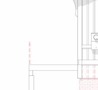
ATTIC BEAM TO SUPPORT LINTEL, REF. STRUCTURAL DVL DVL CEILING FRAMING 3/4'' T&G SHIPLAP 3/4" T&G PLYWOOD ATTIC SUBFLOOR MIN. 2'' CLEARANCE, REF. MANUFACTURER INSTRUCTIONS MIN. 2'' CLEARANCE, REF. MANUFACTURER INSTRUCTIONS STEPPED THROUGH WALL FLASHING W/ WEEP HOLES BETWEEN BRICKS @ EVERY STEP 8'' MIN. MORTAR NET WEATHER RESISTANT BARRIER PRECAST CHIMNEY CAP DT DT DT DT DT DT DT DT 2' - 8" 2' - 8" 5' 6 3/4" 7" METAL CHIMNEY CAP FLASHING 4 3/4" CONCRETE HEARTH STRUCTURE. NFPA 211 - 11.3: 4" NONCOMBUSTABLE CLEARANCE SHALL BE MAINTAINED DIRECTLY BELOW UNDERSIDE OF HEARTH. BRICK SOLDIER COURSE 3/4" PLYWOOD SHEATHING WOOD FLOOR PROVIDE METAL FLASHING SHEET BETWEEN MASONRY AND FRAMING MIN. R-19 SPRAY FOAM INSULATION PT 2X8 RAFTERS, REFER TO STRUCTURAL W/ MIN. R-30 SPRAY FOAM INSULATION 3/4" T&G PLYWOOD SHEATHING 3/4'' T&G SHIPLAP 3/4" T&G PLYWOOD SUBFLOOR 3/4'' T&G HEART PINE FLOOR 3/4" T&G PLYWOOD SHEATHING BRICK & CONCRETE FOUNDATION PIER, REF. STRUCTURAL CONTINUOUS FOOTING, REF. STRUCTURAL PLYWOOD SHEATHING EXPOSED HEAVY TIMBER RAFTERS, REF. STRUCTURAL BUILT-IN PANTRY & CABINETS 2X SLEEPER @ PORCH FRAMING CONCRETE PARGE COAT PRINTED ON: FILE LOCATION: SCALE SHOWN ON DRAWINGS IS ONLY CORRECT IF THIS SHEET IS PRINTED AT 24"X36" 10/27/2023 12:50:22 PM C:\Users\Brittany Smith\Documents\Thompson DogtrotMain CabinCENTRAL MODEL_BrittanyCohen.rvt 3/4" = 1'-0" 1 WALL SECTION @ FIREPLACE 3/4" = 1'-0" 2 WALL SECTION Hearth section w/ potbelly stove
DURATECH
PIPE BLACK 4X4
STEEL
IN

13
Stain
2
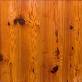
¾’’ Heart Pine Wide Plank Flooring-
No
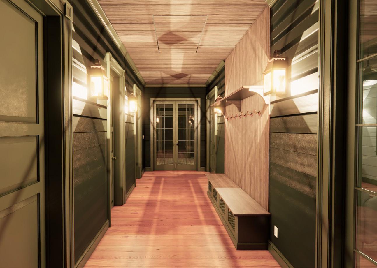
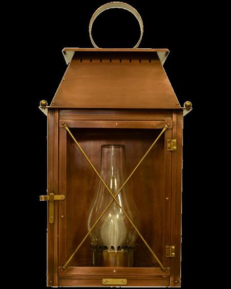
Electric Hallway Light Fixture
Bedroom cabinetry
Dogtrot hallway
Great room hearth
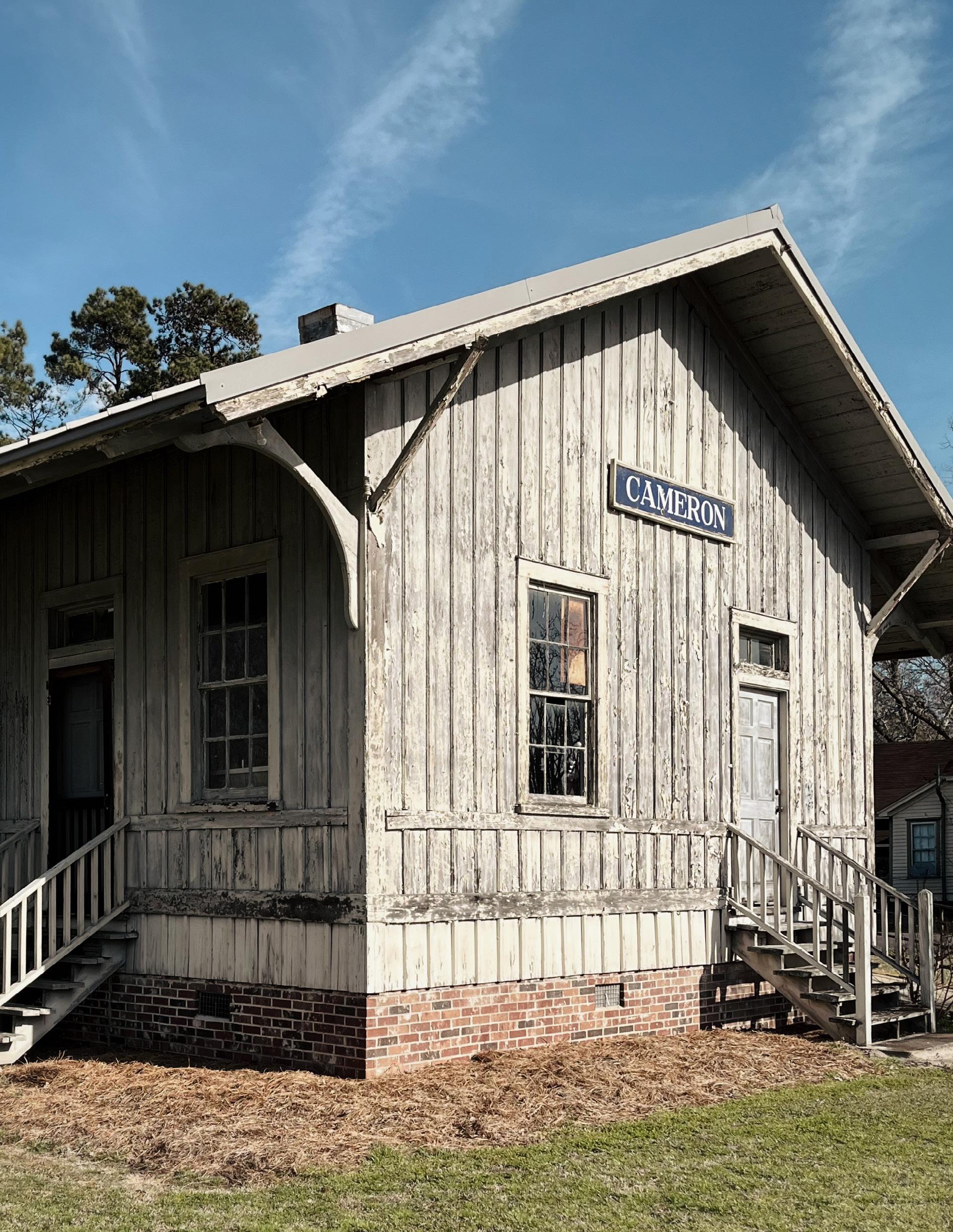
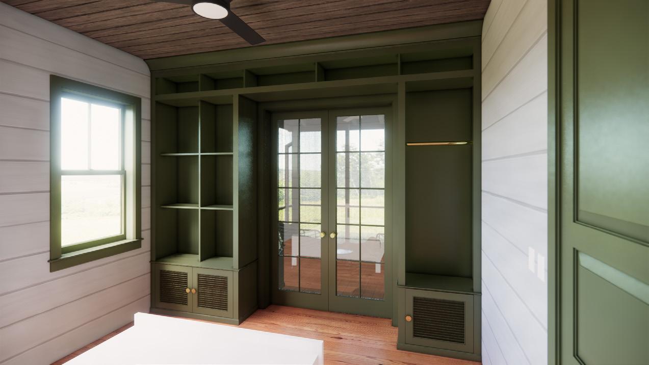
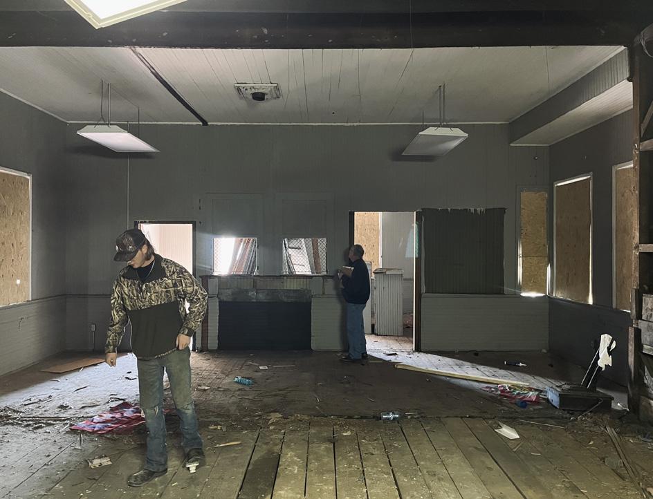
CAMERON TRAIN DEPOT
Cameron, SC
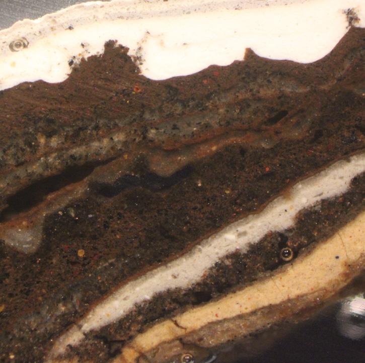
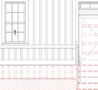
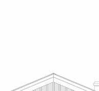
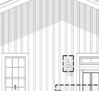
The Town of Cameron, South Carolina, has moved its Train depot three times to avoid being demolished by modern easements. The Town is now planning on turning the building into a community gathering space. With limited state funds, the project is being phased into two stages, phase one is a rehabilitation of the historic exterior while phase two will focus on the update of the interior into an accessible event space for the public. The exterior of the building was constructed using a traditional board and batten method over a 4’’ thick timber frame. Our main design goal is to preserve as much historic fabric as possible, even flipping sections of exterior trim. New windows and doors will be installed into the existing door openings to improve the quality of light on the interior at the rear of the structure. A paint study was performed by our conservation team to discover the original color of the building.
Under Construction
Architect: Meadors, Inc.
GC: Solid Structures
15
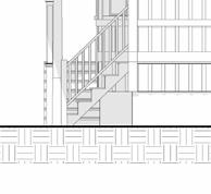
16 REF. ELEC. METER A201 SOUTH ELEVATION 2 A301 A202 EAST ELEVATION A201 NORTH ELEVATION A203 WEST ELEVATION 1 A301 3 A301 1036 SF BANQUET HALL 106 151 SF LOBBY 100 265 SF CORRIDOR 102 184 SF ANTE ROOM 101 160 SF WARMING KITCHEN 108 51 SF STORAGE 107 47 SF FAMILY 105 44 SF FAMILY 104 22 SF JANITOR 103 ø5' 0" ø5' 0" 101 102 103 106 107 108 109 114 115 116 117 118 W3 W2 W1 W4 W5 W6 W7 W8 123 119 120 122 121 NEW EXTERIOR STAIRS AND RAILINGS NEW PLATFORM DECK AND RAILING NEW PLATFORM DECK AND RAILINGS NEW EXTERIOR STAIR AND RAILINGS NEW ADA RAMP AND RAILINGS NEW DOOR SLAB NEW DOOR SLAB RESTORE, REPAIR, AND REPAINT STAIRS AND RAILINGS NEW EXTERIOR STAIR, LANDING, AND RAILINGS WT2 WT1 WT1 WT1 WT1 WT1 WT1 WT1 INFILL WALL FRAMING, MATCH ADJACENT FINISHES REHANG EXISTING RESTORED SLIDING DOUBLE BARN DOORS AND FASTEN TO EXISTING WALL ALONGSIDE DOOR (TYP. 5 LOCATIONS). INFILL WALL FRAMING, MATCH ADJACENT FINISHES RETAIN AND RESTORE EXISTING TICKET WINDOWS A801 1 A803 9 A802 3A A801 4A 3B 3C 3D 4B 4C 4D DRINKING FOUNTAINS A803 1A 1D 1C 1B 110 111 112 113 105 104 47 SF STOOP 111 711 SF CORRIDOR 109 562 SF PLATFORM 110 NEW CASED OPENING ALT #2 ALT #1 ATTIC HATCH ABOVE HVAC OUTDOOR UNIT LOCATION, REF. SPECIFICATIONS FOR OUTDOOR UNIT DETAILS 3' 3" 3' 6" A202 EXISTING EAST ELEVATION A201 EXISTING NORTH ELEVATION A201 EXISTING SOUTH ELEVATION A203 EXISTING WEST ELEVATION UNINSTALL SLIDING BARN DOORS AND SECURE SAFELY FOR RESTORATION AND REINSTALLATION LATER IN PROJECT (TYP OF 5 LOCATIONS). REMOVE PLUMBING FIXTURES AND PLUMBING LINES COMPLETE REMOVE NONHISTORIC INTERIOR WALLS COMPLETE REMOVE ALL CEILING AND FLOOR FINISHES COMPLETE TO PREP AREA FOR RESTORATION OF HISTORIC FABRIC REMOVE DOOR AND FRAME COMPLETE AND PREPARE FOR WALL INFILL REMOVE DOOR SLAB ONLY AND PREPARE JAMB FOR NEW DOOR SLAB REMOVE DOOR SLAB ONLY AND PREPARE JAMB FOR NEW DOOR SLAB AND NEW HANDING REMOVE STEPS AND RAILING COMPLETE REMOVE CONCRETE RAMP AND RAILINGS COMPLETE REMOVE DOOR AND FRAME AND PORTION OF WALL. REFER TO PROPOSED PLAN REMOVE HISTORIC INTERIOR WALL AND SALVAGE FRAMING AND FINISH MATERIAL FOR POSSIBLE PATCHING AND USE IN THE RESTORATION PORTION OF THE WORK. REMOVE EXISTING BUILT-IN CASEWORK REMOVE ALL CEILING AND FLOOR FINISHES COMPLETE TO PREP AREA FOR RESTORATION OF HISTORIC FABRIC REMOVE AND RELOCATE EXISTING ELECTRICAL PANEL WT1 WT2 EXISTING WALL NEW WALL WALL LEGEND PRINTED ON: FILE LOCATION: 6/8/2023 11:31:40 AM P:\Projects\21-0158 Cameron Train Depot\1300 Model\1301 C urrent Model\Train Depot_Central Model.rvt SQUARE Room Number Room Name 01 - 1ST FLR 100 LOBBY 101 ANTE ROOM 102 CORRIDOR 103 JANITOR 104 FAMILY 105 FAMILY 106 BANQUET HALL 107 STORAGE 108 WARMING KITCHEN 109 CORRIDOR 110 PLATFORM 111 STOOP Grand total 1/4" = 1'-0" 2 01 1ST FLR PLAN 1/4" = 1'-0" 1 01 1ST FLR DEMO PLAN 1" = 1'-0" WALL TYPE REF. A106 FOR SCOPE OF WORK ALTERNATES First floor demo plan First floor plan


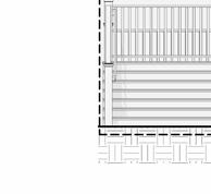
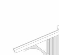

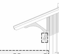
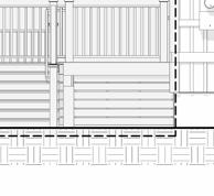
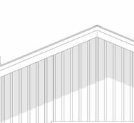
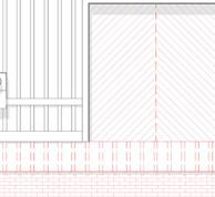


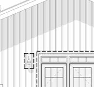
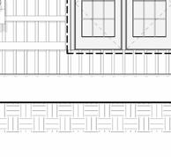

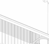
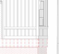


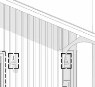
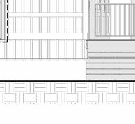


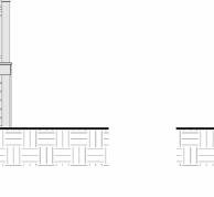
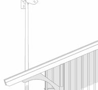
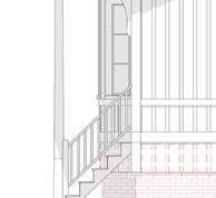

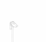
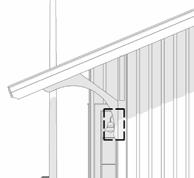
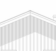

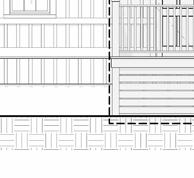
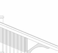
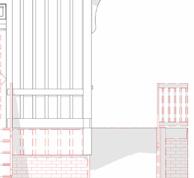


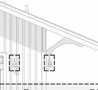
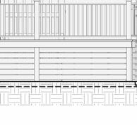


17 01 - 1ST FLR 12' - 0" 00 - GRADE PLAN 8' - 0" 1 A301 4 A701 NEW BOARD AND BATTEN SIDING BELOW TRIM BAND TO MATCH AND ALIGN WITH EXISTING NEW EXPANDED PLATFORM, DECKING, STAIR, AND RAMP SYSTEM CONSTRUCT NEW 12'' CMU FOUNDATION WALL. FINISH WITH THREE COAT STUCCO FINISH INSTALL NEW FENESTRATION SYSTEM IN EXISTING CASED OPENING. REINSTALL RESTORED AND REFURBISHED DOUBLE BARN DOORS TO INTERIOR. NEW GAPPED P.T. 2x6 INFILL SCREEN B/W PIERS 1 A702 ALT #1 01 1ST FLR 12' - 0" 00 - GRADE PLAN 8' - 0" 1 A301 4 A701 3 A701 2 A702 NEW BOARD AND BATTEN SIDING BELOW TRIM BAND TO MATCH AND ALIGN WITH EXISTING NEW EXPANDED PLATFORM, DECKING, STAIR, AND RAMP SYSTEM CONSTRUCT NEW 12'' CMU FOUNDATION WALL. FINISH WITH THREE COAT STUCCO FINISH NEW DOOR SLAB NEW GAPPED P.T. 2x6 INFILL SCREEN B/W PIERS ALT #1 01 - 1ST FLR 12' - 0" 00 - GRADE PLAN 8' - 0" SLIDING BARN DOORS TO BE REMOVED, SAVED, REFINISHED & REPAIRED WHERE REQUIRED, AND REINSTALLED REMOVE NON-HISTORIC SINGLE WYTHE BRICK SKIRT WALL COMPLETE REMOVE NON-HISTORIC BOARD AND BATTEN SIDING BELOW BOTTOM TRIM BAND COMPLETE 01 - 1ST FLR 12' - 0" 00 - GRADE PLAN 8' - 0" REMOVE EXISTING DOOR SLAB AND PREPARE FOR NEW WOOD DOOR SLAB REMOVE FRONT STAIRS AND NON-HISTORIC RAMP TO ACCOMMODATE EXPANDED PLATFORM AND ENTRY RAMP/STAIRS. REMOVE NON-HISTORIC SINGLE WYTHE BRICK SKIRT WALL COMPLETE REMOVE NON-HISTORIC BOARD AND BATTEN SIDING BELOW BOTTOM TRIM BAND COMPLETE NEW. ALL WORK PENETRATIONS REQUIRED MECHANICAL, PLUBMING. ANY WORK STANDING SEAM METAL COMPLIANCE WITH STANDARDS. REPAIR ELEMENTS THAT ARE IN LEAKING. COORDINATE WITH THE PAINT FROM ALL ELEMENTS. THE HISTORIC STRUCTURE. FEDERAL, STATE, AND ORDINANCES, LAWS, AND WORKING WITH MATERIALS AND LEAD HISTORIC WOOD ELEMENTS THOSE ELEMENTS DETERIORATED TO SAVE. WHERE REQUIRED. AND BATTEN SIDING BOTTOM TRIM BAND. NEW SIDING BELOW TRIM AND ALIGN WITH EXISTING BOARD AND TO BE REPLACED FOR SURFACES AND THEN FINISH COATS OF EXISTING GLAZING ALL WINDOW SASHES GLAZING. ALLOW FOR PROPER TIME WITH OIL-BASED TOPPING WITH TWO FINISH WINDOW SASHES TO REPLACING HARDWARE EXTERIOR PEDESTRIAN OPERABLE FUNCTIONING ONLY THOSE ELEMENTS REPAIR WITH IN-KIND NEW WEATHERPSTRIPPING, SWEEPS, AND ADA THREHOLDS. DOUBLE SLIDING HARDWARE. THESE REINSTALELD INTERIOR FENESTRATION SYSTEM. DOORS TO REMAIN STATE OF SCRAPE LOOSE PAINT SIGNAL POLE. RESTORE FINISH COATS. AND RAILINGS TO RESTORED AND ONLY DAMAGED ELEMENTS. SCRAPE PRIME, AND APPLY TWO PAINT TO RAILINGS, STRINGERS, AND ALL PLATFORM TO REMAIN. BOARDS THAT ARE REPAIR. REATTACH RESUPPORT BOARDS. REFINSIH ALL DECKING AND EXISTING FLOORBOARDS FOR BID. PLATFORM EXENSIONS TO MATCH THE WITH PRIMER AND TWO ADA RAMP. EXTERIOR STAIRS AND NON-HISTORIC SINGLE WYTHE COMPLETE. 12'' CMU FOUNDATION 3/8'' STUCCO BASE STUCCO FINISH COAT. MATERIALS TESTING WAS OF 2023. REFERENCE ASBESTOS AND LEAD REPORT FOR ADDITIONAL ASSUME LEAD PAINT IS PAINTED SURFACES. SCOPE: S N C E 1 9 8 4 M E A D R S 2811 AZALEA DRIVE CHARLESTON, 843.723.8585 PROJ. NO. ISSUE DATE: A201 BUILDING ELEVATIONS 21-0158 CAMERON TRAIN DEPOT CAMERON, SC 06/09/2023 BID SET 1/4" = 1'-0" 3 NORTH ELEVATION 1/4" = 1'-0" 4 SOUTH ELEVATION 1/4" = 1'-0" 1 EXISTING NORTH ELEVATION 1/4" = 1'-0" 2 EXISTING SOUTH ELEVATION CHI TERED AR E IREG No. 9388 S SO OF UTH RO TECT CA TE STER C ED AR HI NA 100192 Charleston, SC T R S EGI ATEOF CTS SOUTH CAROLI MEADORS, INC. REVISIONS # DATE NOTES
Interior demo progress
Elevations
elevations
Cross section of an exisitng paint chip under the microscope
Existing


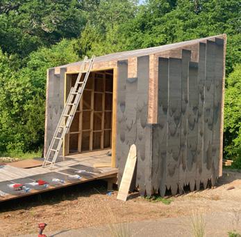
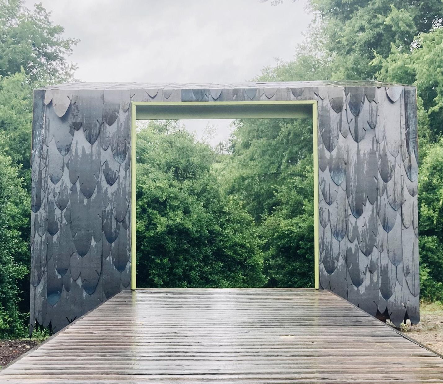
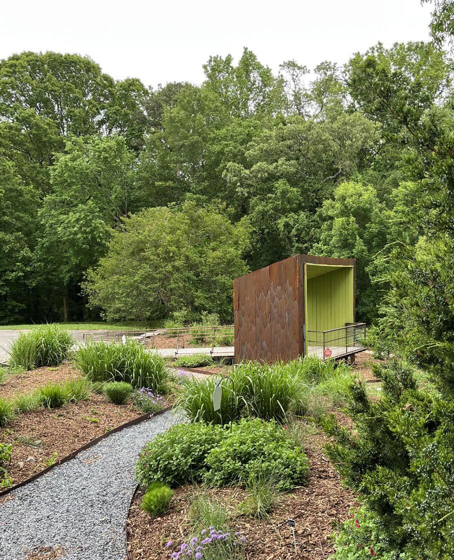
birdBOX
South Carolina Botanical Garden
The South Carolina Botanical Gardens and the Clemson University School of Architecture partnered to design and build a structure for bird watching in the Botanical Gardens’ most visited birding location. With a focus particularly on Warblers, the structure was located in an area of the gardens where it could angle toward the areas of focus, two Hackberry trees. The structure itself acts as an aperture for this area as the sides and top angle up and away to the garden. The shape of the cladding, layered metal shingles, was designed as an abstraction of a bird feather to resemble the warblers themselves. These “feathers” were carefully designed to be overlapped to protect the structure from the elements and hide the screw holes from sight. The garden retaining wall was constructed from layers of the existing asphalt parking lot that were removed to make way and create an entrance for the new structure. The project serves as a beacon of peace for the community.
Completed: 2021
In Collaboration With: Prof. Harding & Clemson University School of Architecture Community Build Students, with special thanks to my partner in fabrication, Aaron Autry
Select Photos: Dan Harding
- Featured on South Carolina’s Public Educational Broadcasting Network | Link: https://www.scetv.org/watch/making-it-grow
19
20
Feathers prior to rust
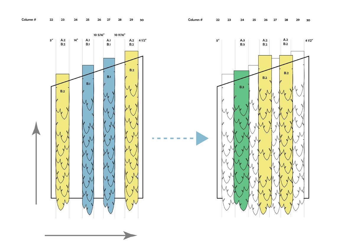
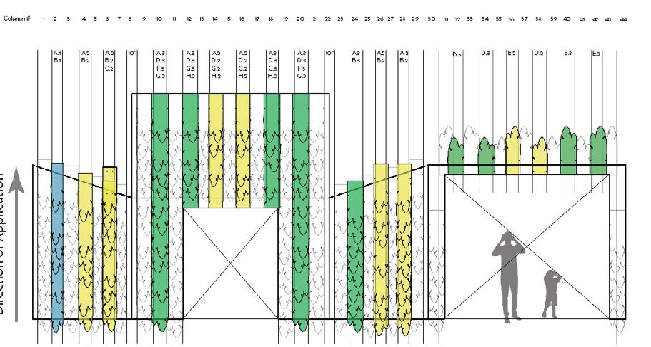
NORTH ELEVATION
THE ACT OF AGING
-Starting on column 22 measure 5” from corner of structure and mark stucture with a chalk line.
-Apply feathers specified in column 23 (overhanging bottom feather between 2”-4”) onto stucture. (See diagrams left) Making sure to align notches at midpoint of feather with the top of the previously attached
-Starting on column 22 measure 5” from corner of structure and mark stucture with a chalk line.
-Apply feathers specified in column 23 (overhanging bottom feather between 2”-4”) onto stucture. (See diagrams left) Making sure to align notches at midpoint of feather with the top of the previously attached feather.
-Measure over specified distance from edges of previously attached feathers and mark again with another chalk line.
-Repeat previous steps with columns 25 & 27 as well.
-For second layer, attach specified feathers over gaps left by previously laid base layer feathers. (Columns 24, 26 & 28) Making sure to overlap the feathers to the right and left.
aligning notches with top of first feather; this allows for more randomness of spacing; feathers can be placed closer together or further apart in this layer as long as no gaps in cladding are apparent.
-Second layer doesn’t require
-Unlabeled feathers are either A.1, A.2 or A.3 depending on color.
-Second layer doesn’t require
The metal feathers were originally specified to be corten steel. However, after a quote came back more than triple the budget, the decision was made to use mild steel without a zinc coating to achieve the desired aesthetic. While this puts a limit on the life of the cladding, it is designed to be removed and replaced easily.
aligning first feather; randomness be placed apart in in cladding
-Unlabeled A.2 or A.3
Feathers A.3: 7 B.1:
21
Base Layer
Direction of Application
Second Layer
ELEVATION
Second Layer Key
Side Base Layer
Side Cover Layer
Feather Layout
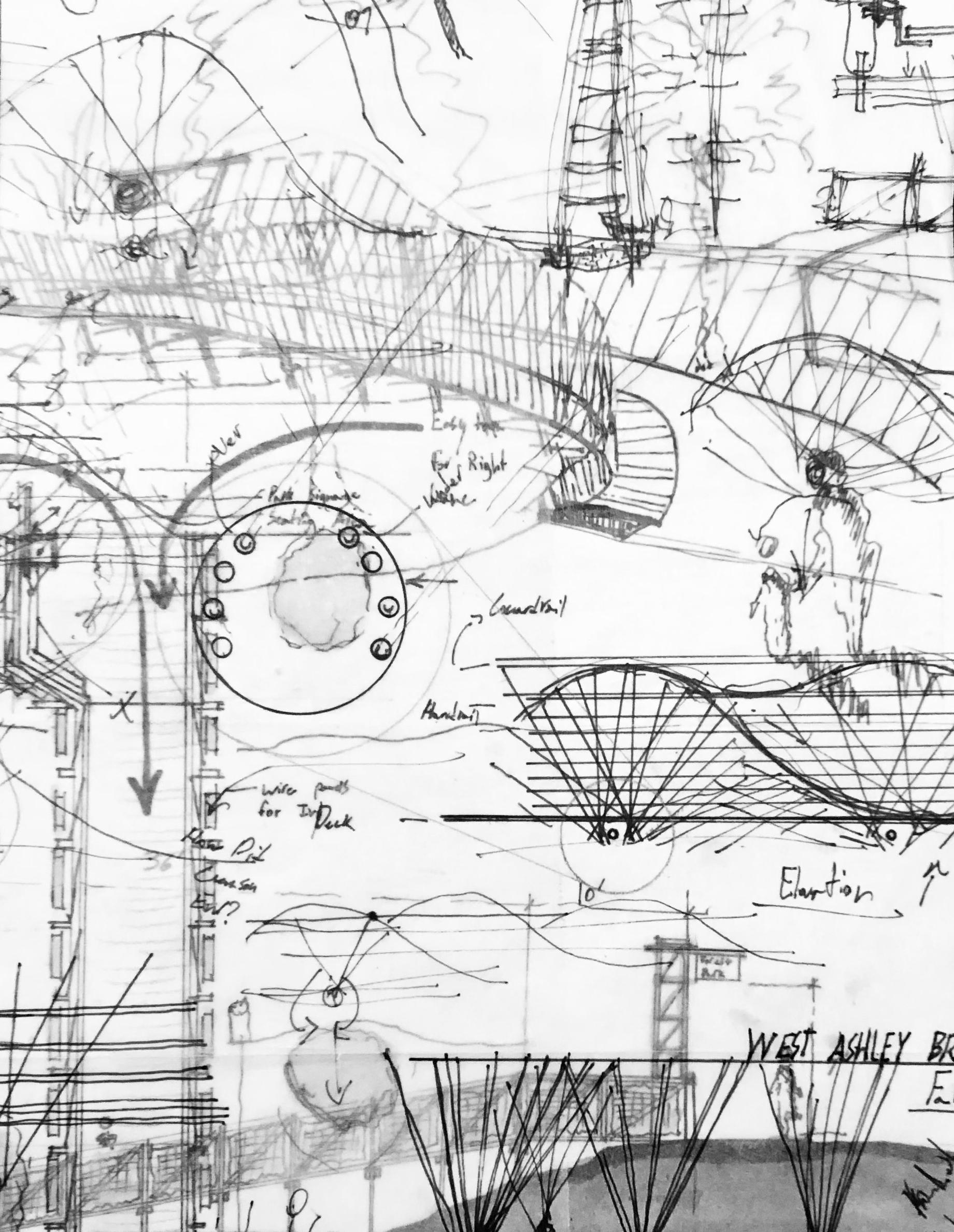
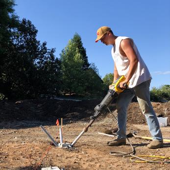
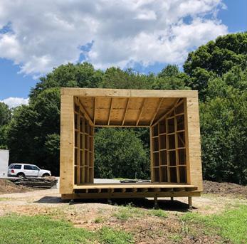
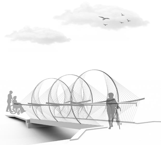
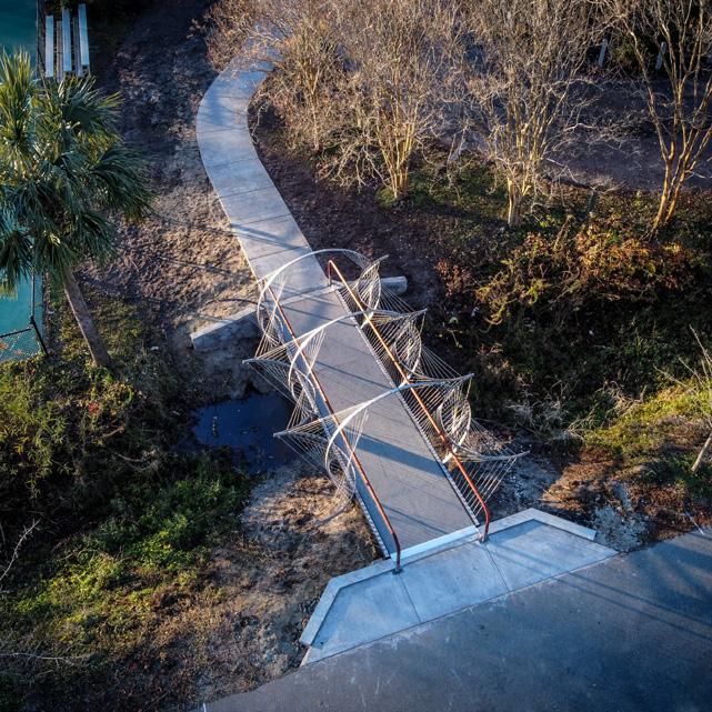
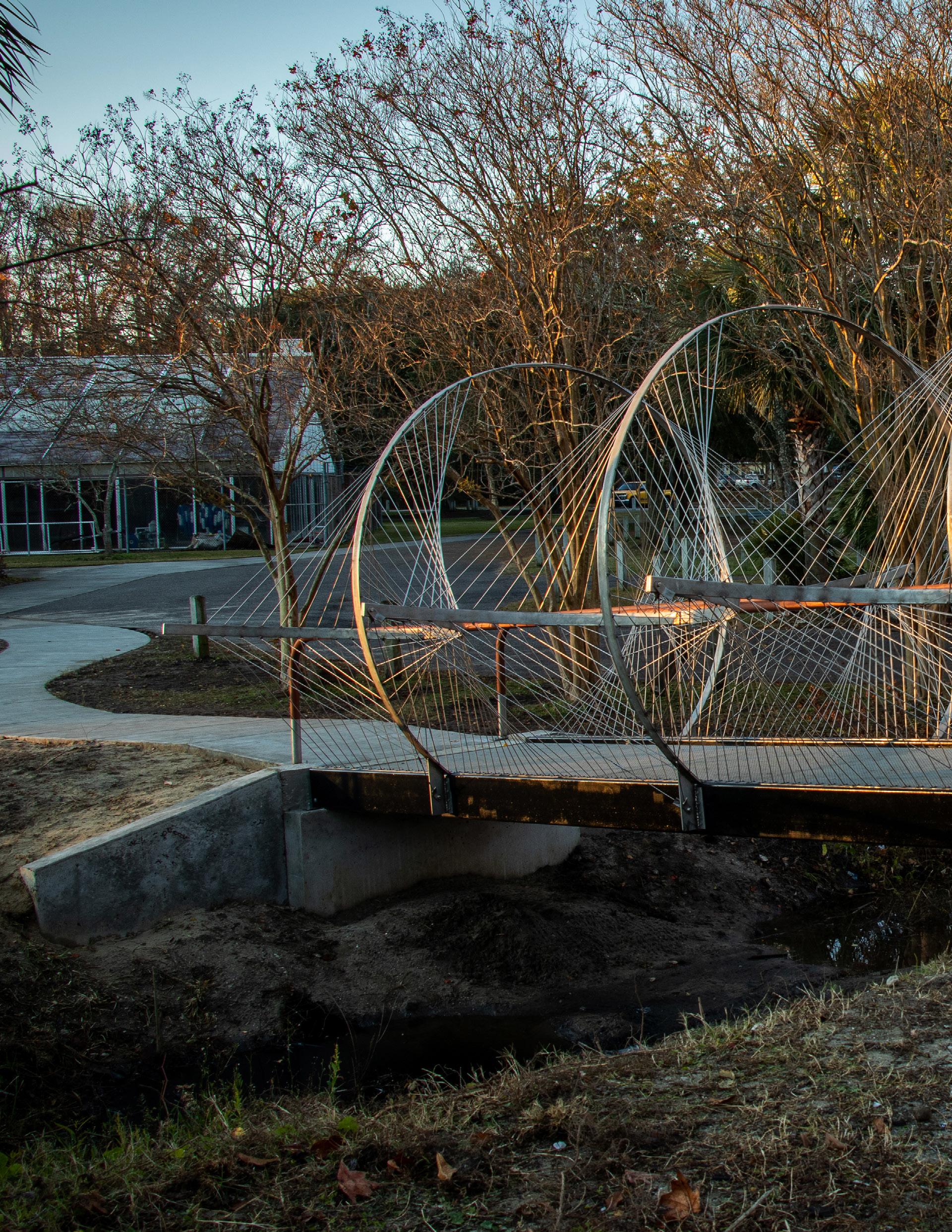
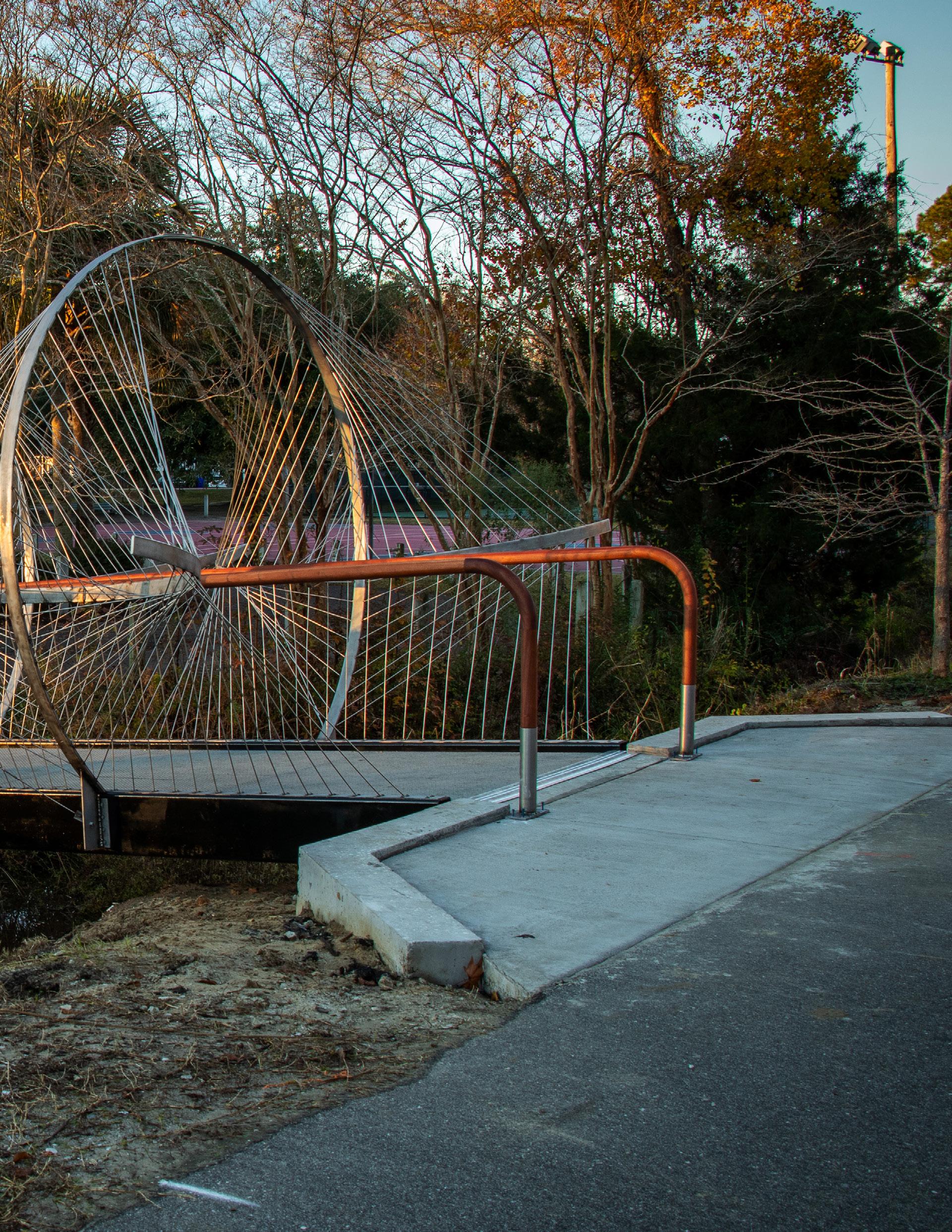
WEST ASHLEY BRIDGE
Charleston, SC
West Ashley is an old community in Charleston with a rich history. As it grows and expands, more focus is being placed on its infrastructure including the West Ashley Bikeway. The Bikeway is a two-and-a-half-mile path that connects many historic neighborhoods and parks. This pedestrian bridge was built in replacement of an older one that had fallen into disrepair. Charleston County Parks department requested that the Clemson design build studio replace it with a “Sculptural” design. After lots of design process, our studio decided to build a bridge with the idea of tensegrity as the driving factor. Developed by Buckminster Fuller, tensegrity is the idea that everything is held together by members in tension. Here we used 3/16’’ stainless steel rod to hold the larger steel rings in place. These rods acted as our guardrails with each rod spaced four inches apart to comply with ADA Code. These six sculptural pieces were held up by two large steel tube beams, measuring 24’ in length.
Prof. Pastre
Complted: 2020
In Collaberation With: CAC.C Studio Community Build
Select Photos: Brian Heape
23
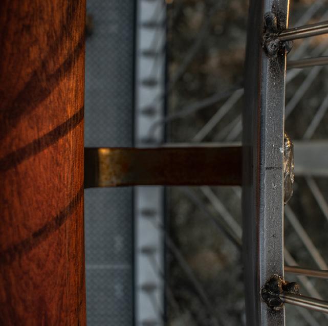
Gusset Detail

24 30 202 06:30:30 02 Gusset Section Detail 13 1/16" 4" 1/4" 4" 2" 2" 2" 1" 8" 43° 1" 1/2" 2" 9 3/4" Weld Weld FRP DECK cut bottom edge corner +Grind 1/8” self taping screw
Bikeway Connection
Handrail Detail


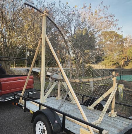
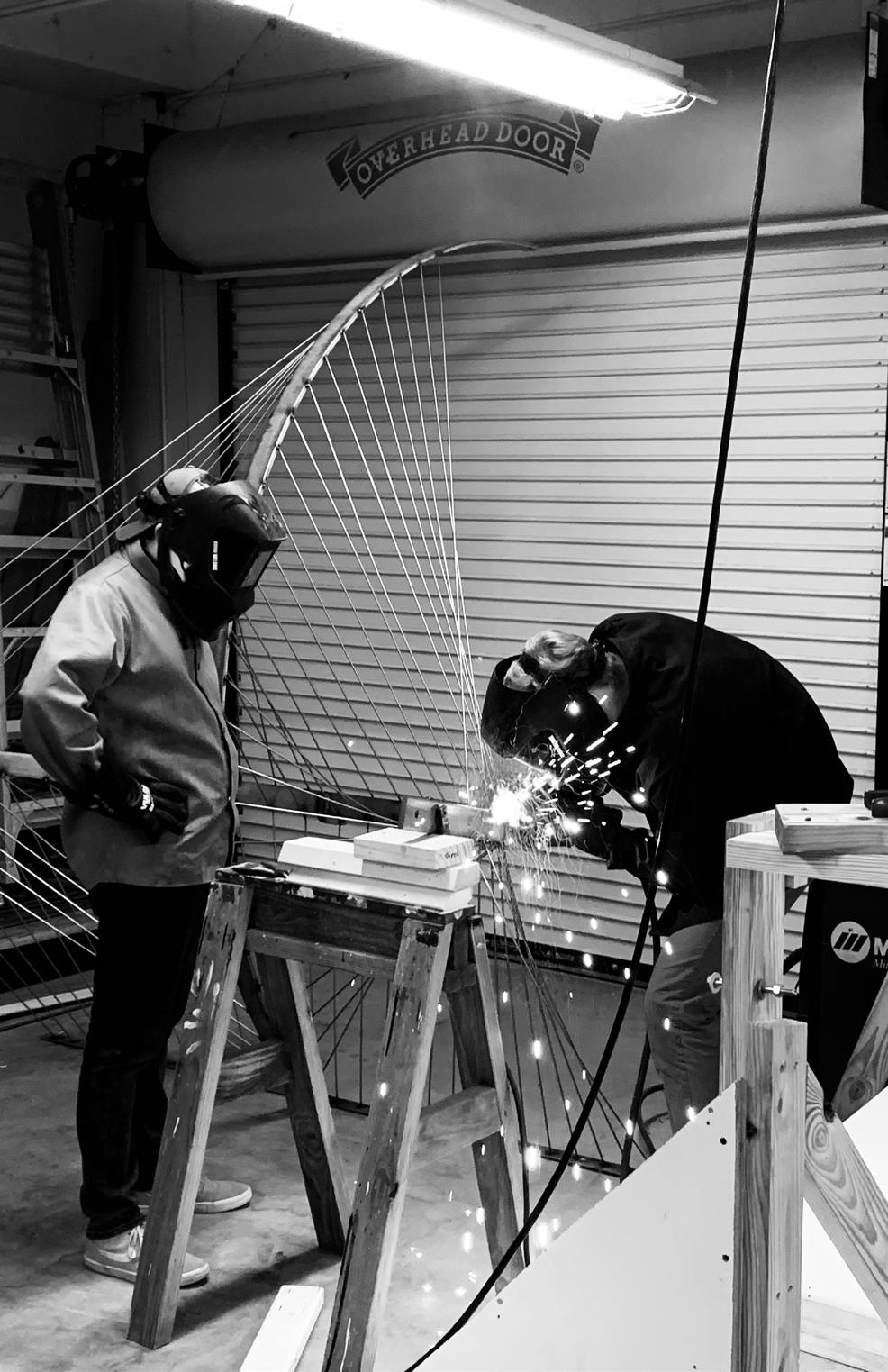
1008 WELDED CONNECTIONS
Each stainless piece of rod was welded onto the larger rings. A wooden jig was created to hold the two rings in space while we welded each rod in place. 84 rods were needed for each piece. This process was repeated 6 times totaling 1008 welded connections.
25
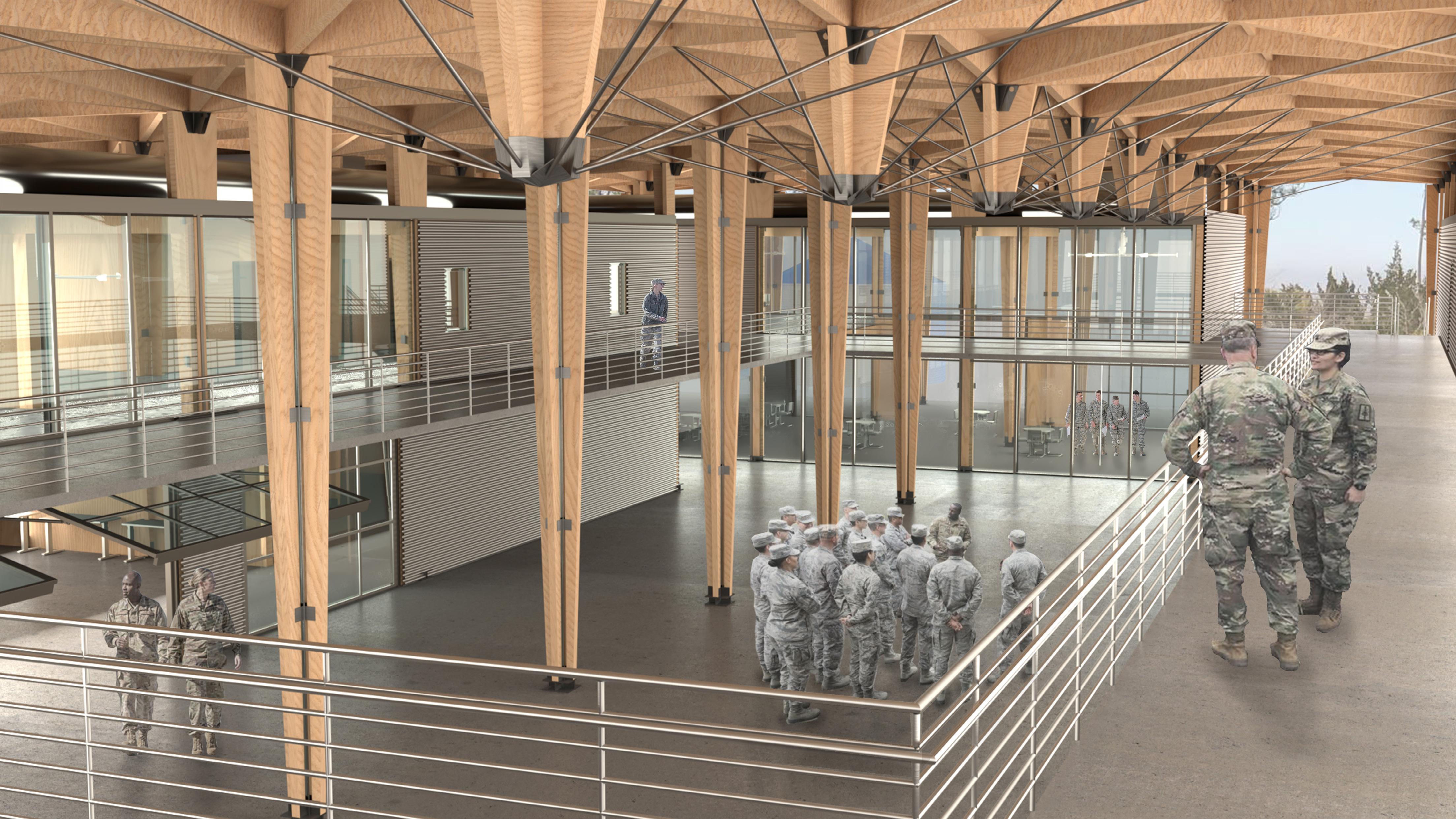
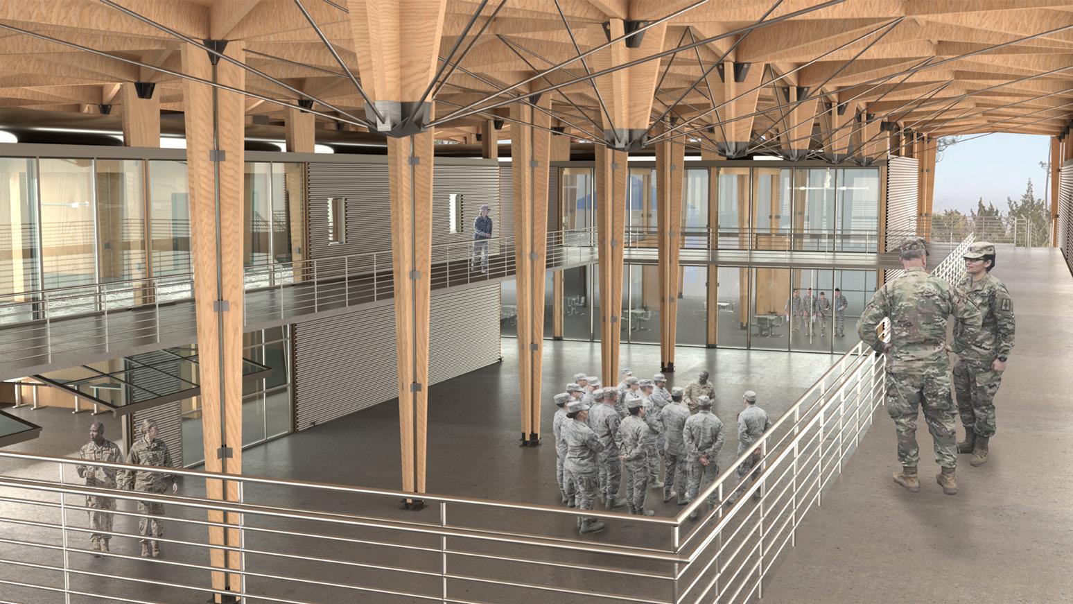
SILVER FLAG HEADQUARTERS
Tyndall Air Force Base, FL
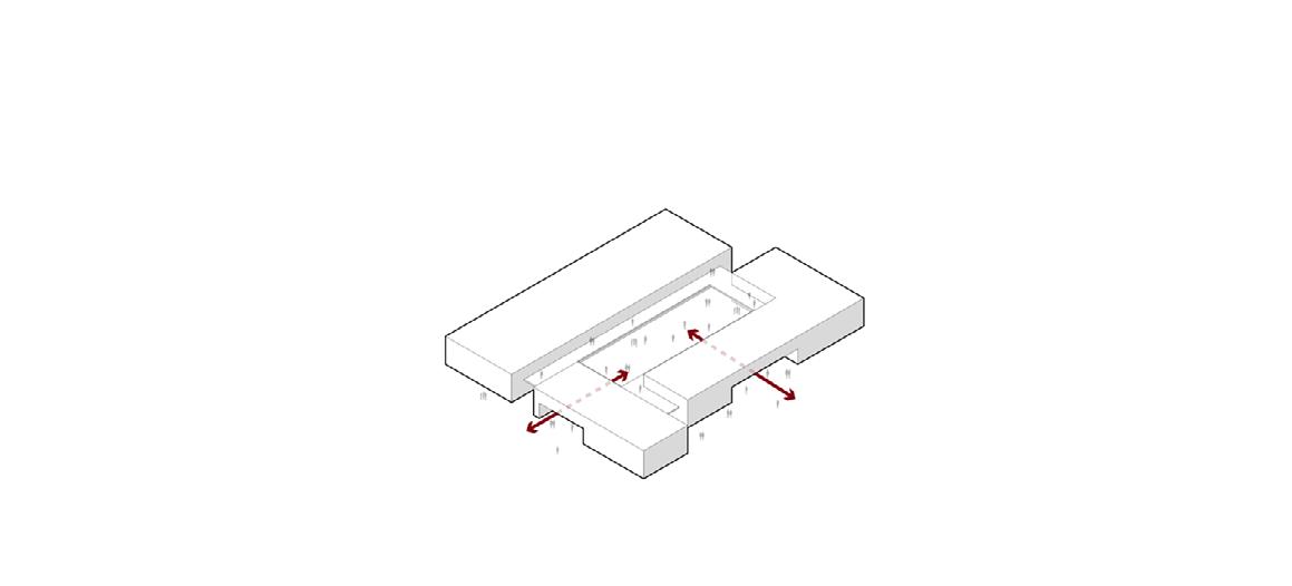
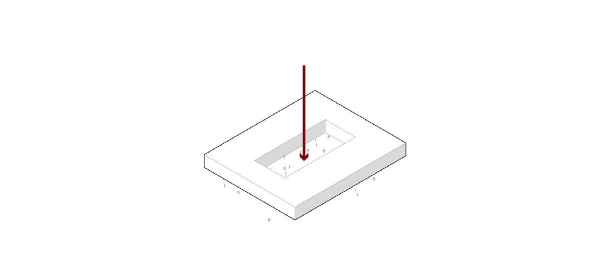
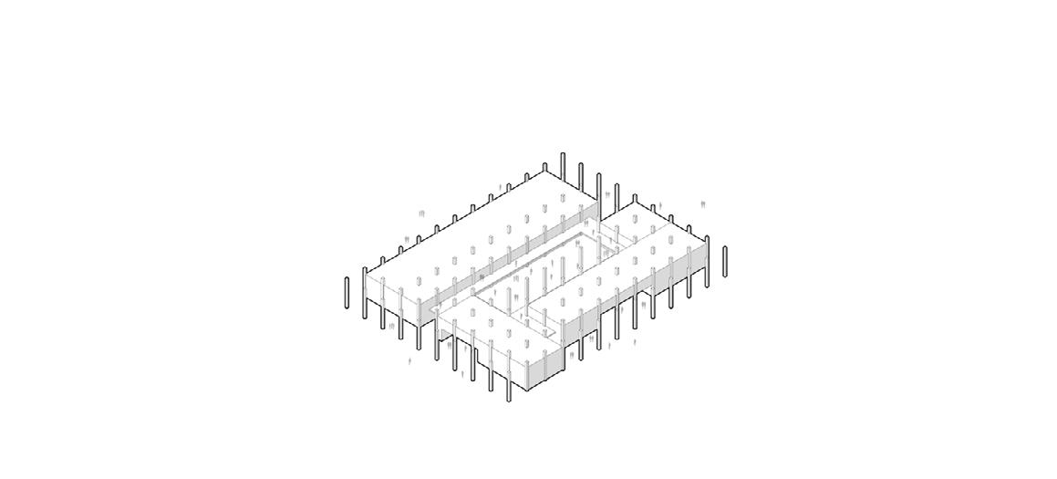
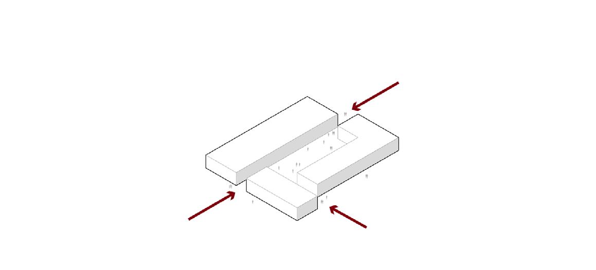
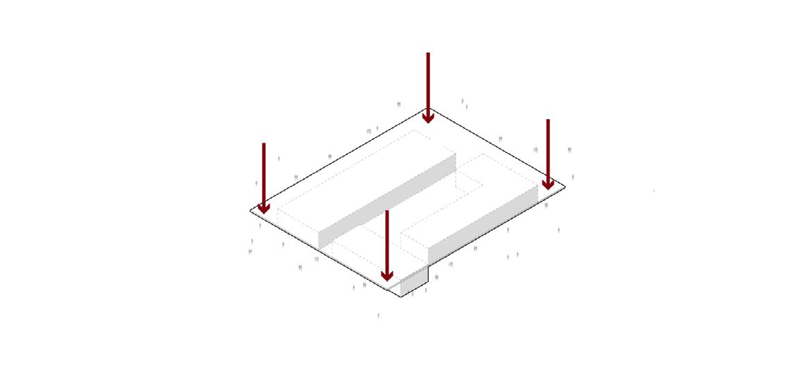
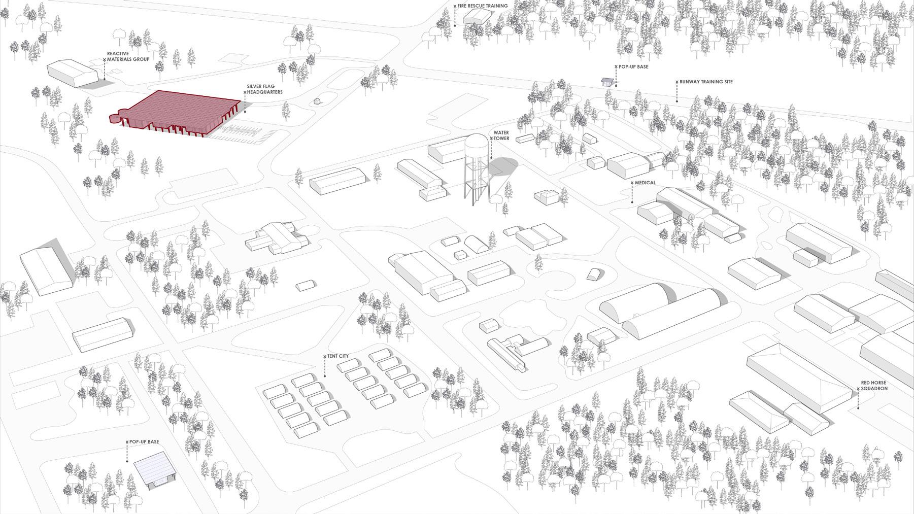
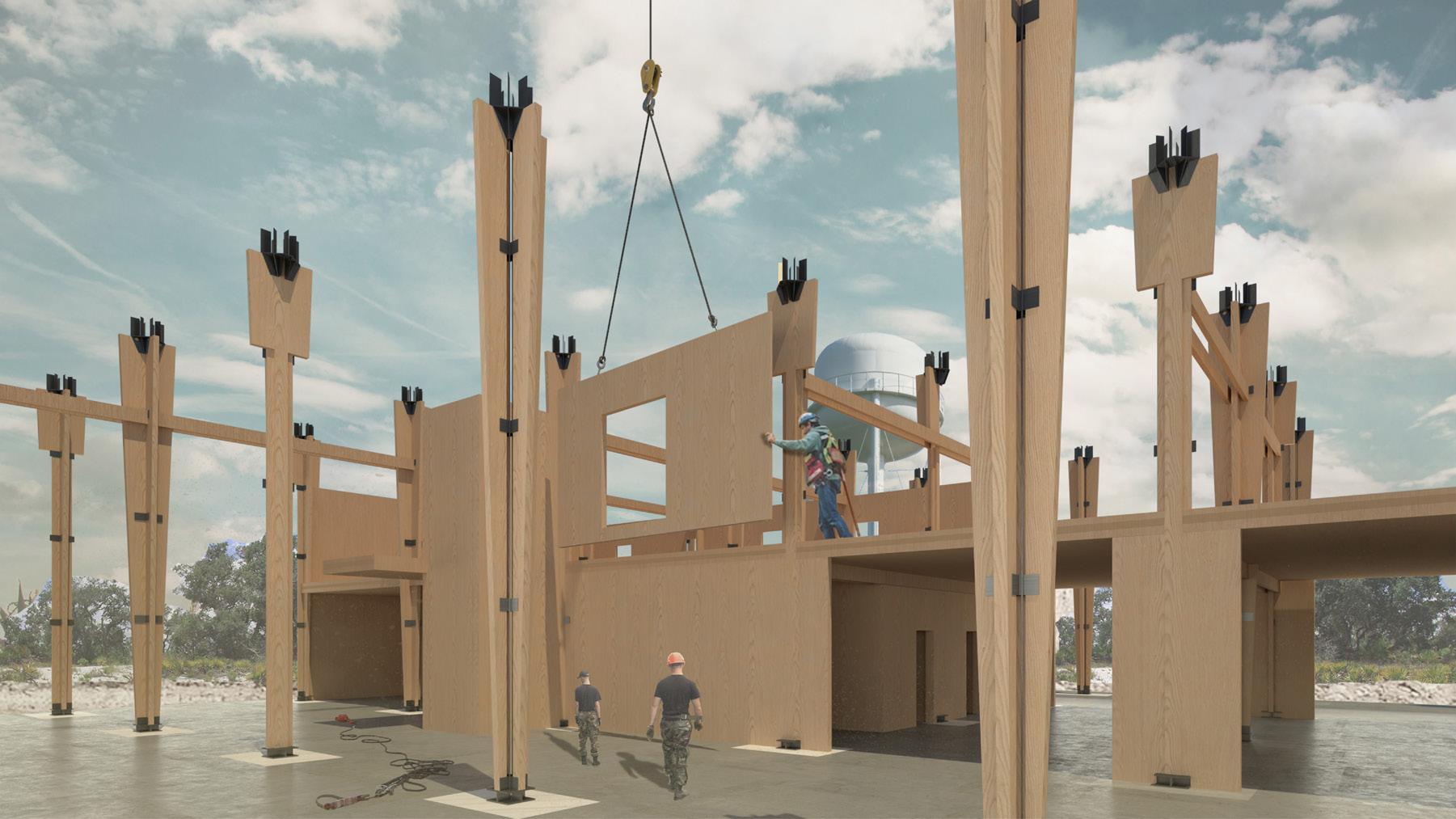
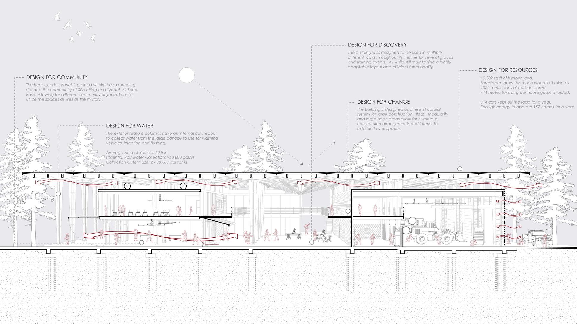
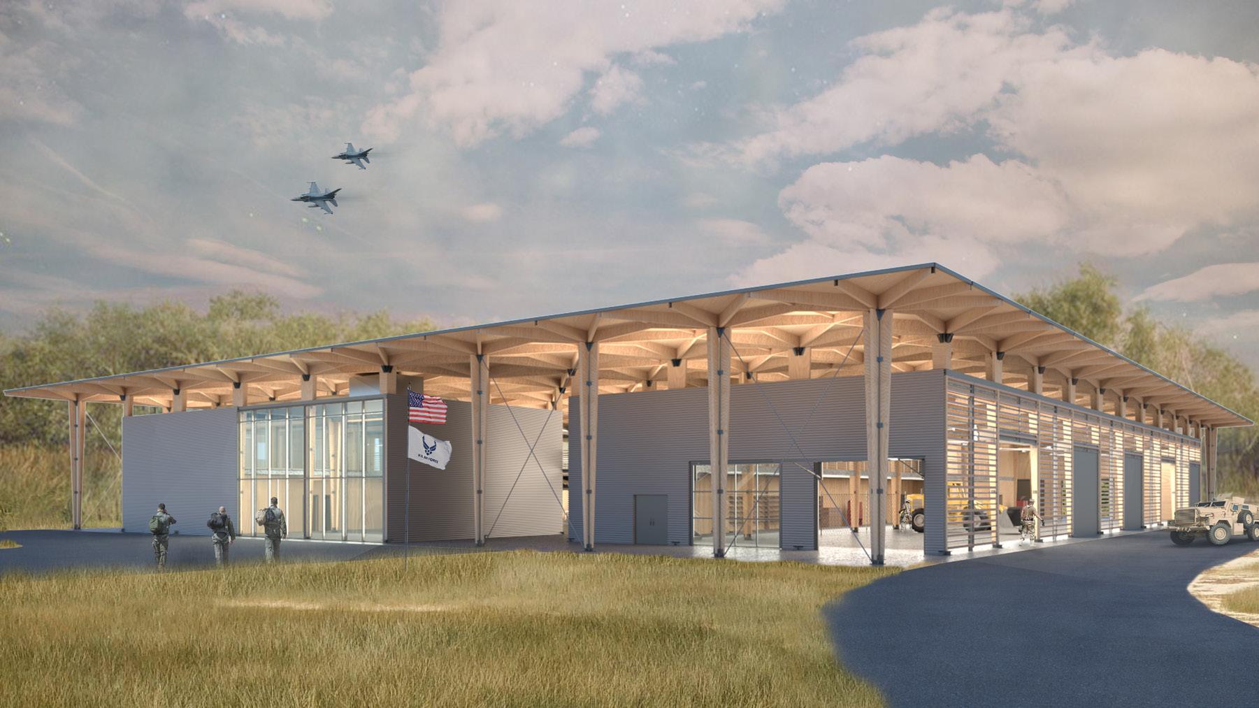
The Silver Flag training program provides United States Air Force Civil Engineers with a chance to prepare for bare base development, sustainment operations and airfield damage repair. With only three locations in the world and just one in North America, the Silver Flag program at Tyndal is both interesting and unique. Located in a remote spot on the base, we saw fit to try to design a “campus” that creates a headquarters for the program and a connection to the surrounding community. Additionally, we designed mobile Pop-Up Bases that can be easily spread across the base to fit the needs of the program in a fast and efficient way. Collaging multiple programmatic functions and environmental solutions into a single structure paved the way for the design of a new CLT framing system.
Profs. Albright, Ersoy, & Harding
Complted: Spring 2021
In Collaberation With: Aaron Autry, Hunter Harwell, & Rachel Baca
- Harlan E. McClure Award Finalist
29
30
grid
Silver Flag training base central space program split access
cover
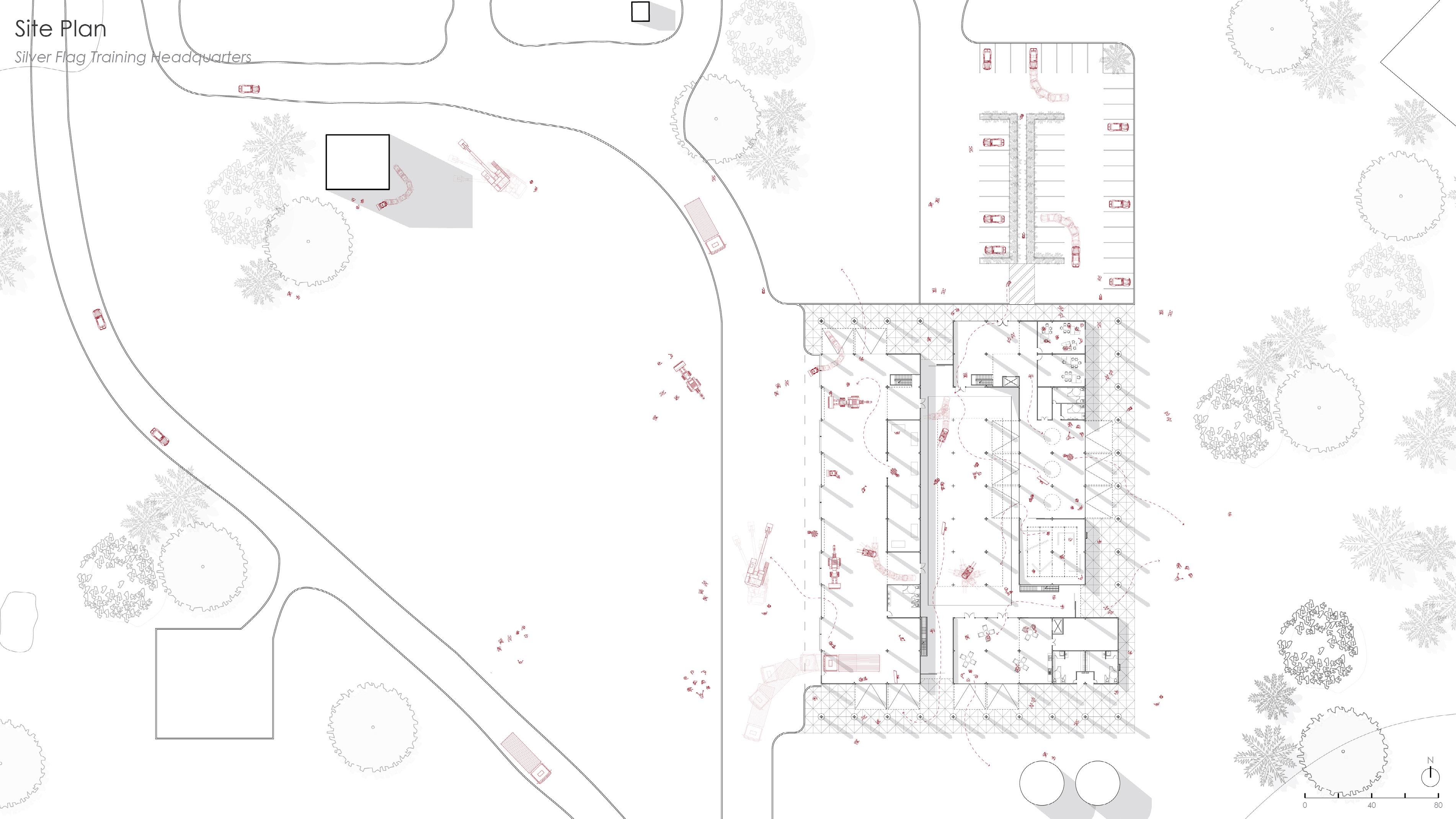

31 First Floor Plan
Vehicle Maintenance
Tool Storage
Bathrooms
Staging Area
Small Assembly Area
Locker Rooms
Tech Lab
Large Classroom
Small Classrooms 10 Entrance Lobby 11 Mech Rooms 1 2 3 4 5 7 6 6 8 11 3 11 3 9 9 10 First floor plan
1
2
3
4
5
6
7
8
9
32
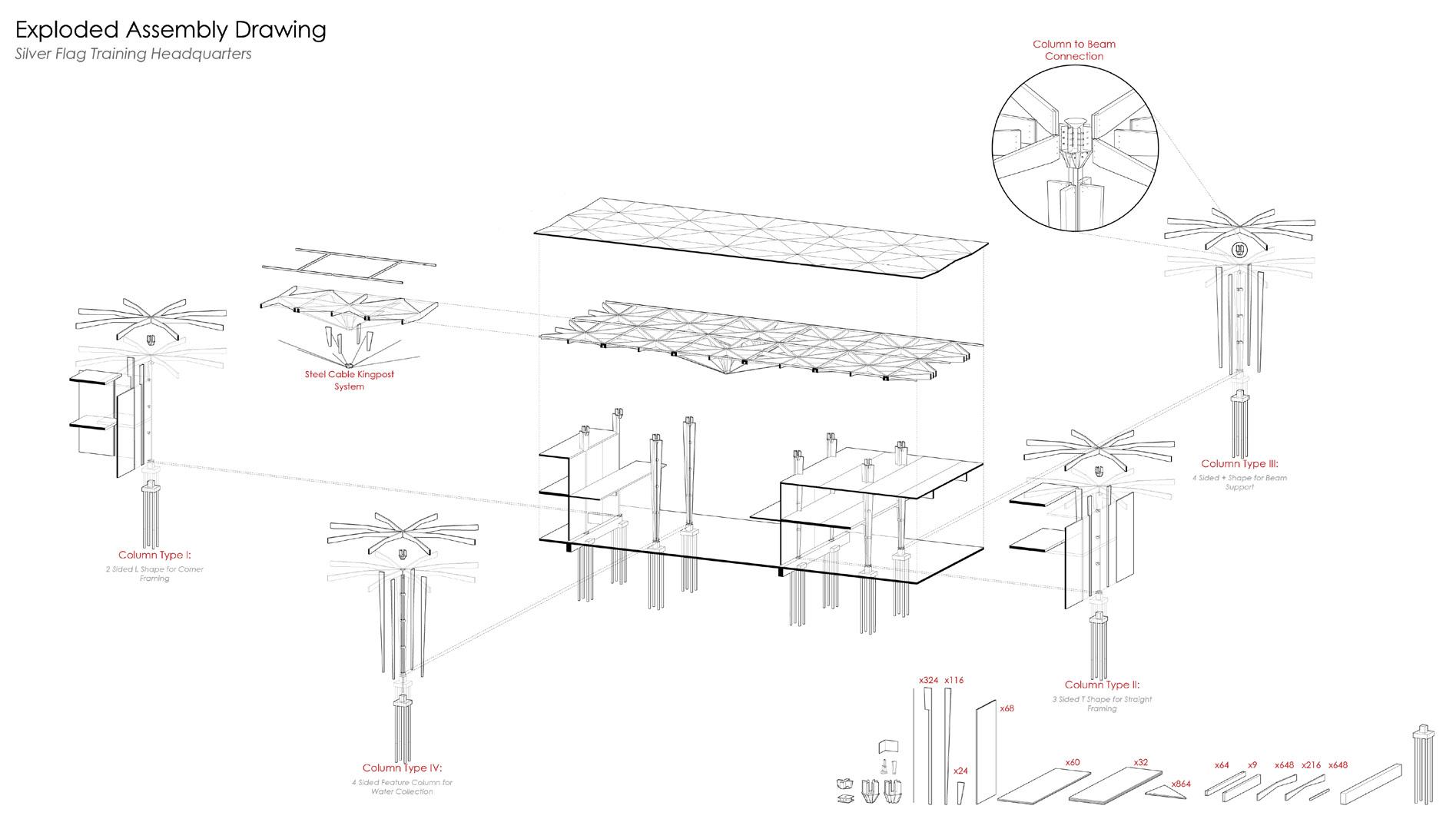
CLT assembly diagram
CLT assembly
33
Front Perspective
Section
THE REVITALIZATION OF CASTELLETTO
Genoa, Italy
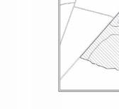
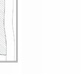
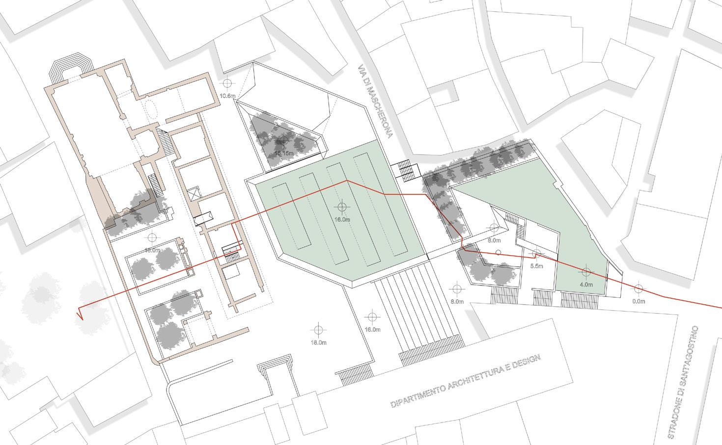
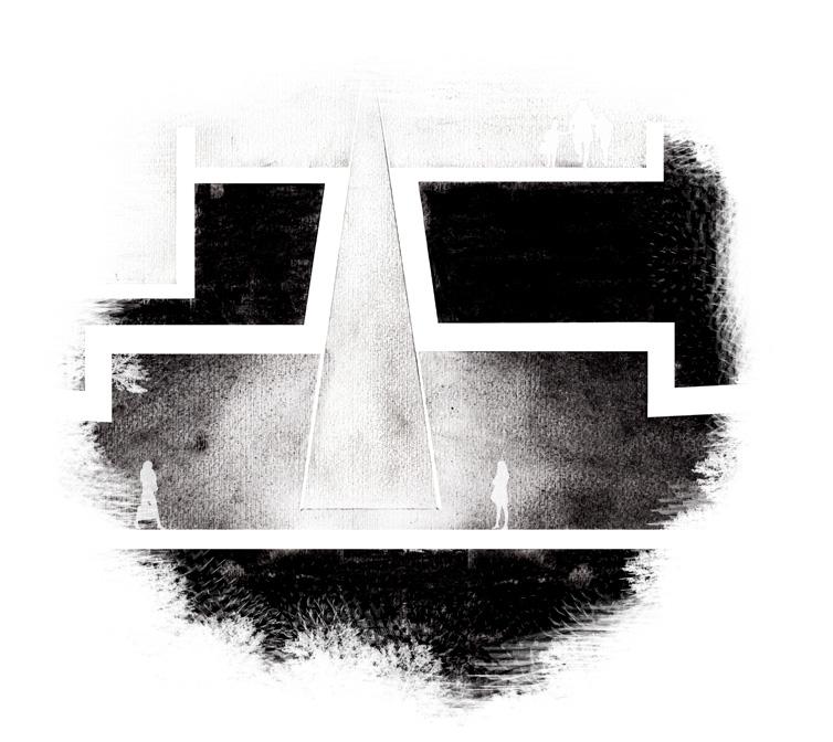
Genoa, Italy’s historic Castelletto Hill was reshaped by allied bombings during WWII. La Chiesa di Santa Maria in Passione was an Italian monastery perched upon the hill and was never fully restored. Our design ambitions became heavily shaped around the existing ruins that dwelled on the site. In effort to preserve as many ruins as possible, we excavated a tunnel underneath the site that eventually leads the visitor to enter the existing ruins from underneath, similar to Aurelio Galfetti’s Castelgrande restoration. There are a series of interventions along this underground path that cause the visitor to pause and reflect on the history of the site, each one playing with light in a different way. Keeping the local preference of “No Business”, the site contains no shops or restaurants, and even includes an underground gallery with a green roof that is dedicated to the art of preserving Frescos.
Profs. Houayek & Rocco
Complted: Spring 2018
In Collaberation With: Doug Shay
35
38
Level G (18m)
1 Existing Ruins
2 Underground Elevator
3 Underground Exit
4 Underground Stair
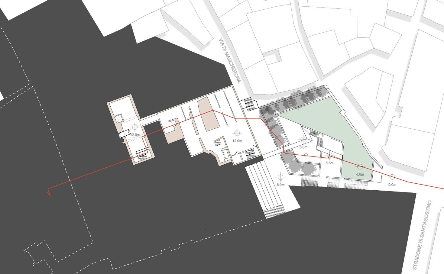
Level -1 (12m)
1 Existing Underground Ruins
2 Roman Cistern
1 2 3 4 1 3 2
3 Museum Exhibit
39
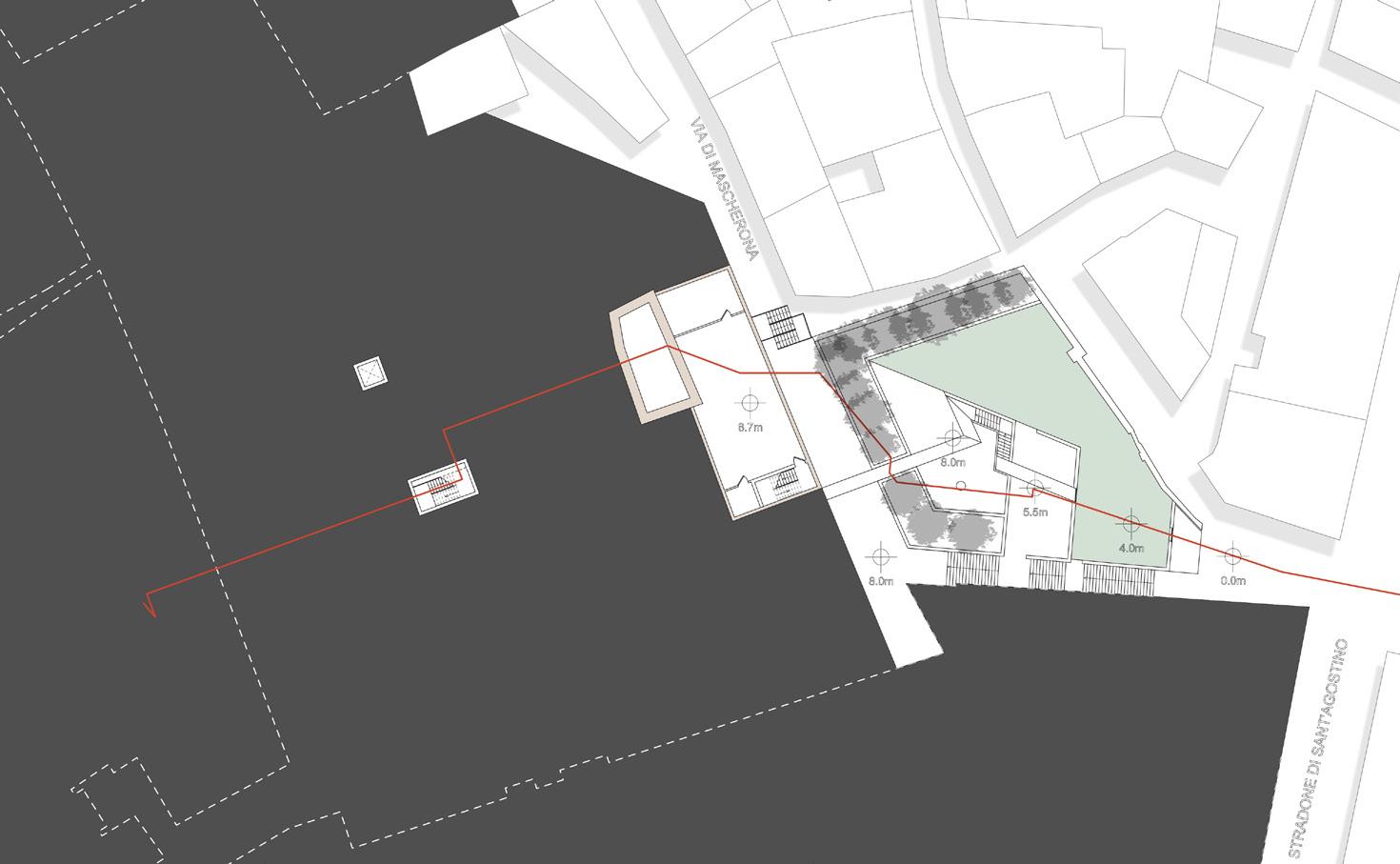
Level -2 (8m)
1 Roman Cistern
2 Curator Office
3 Museum Storage
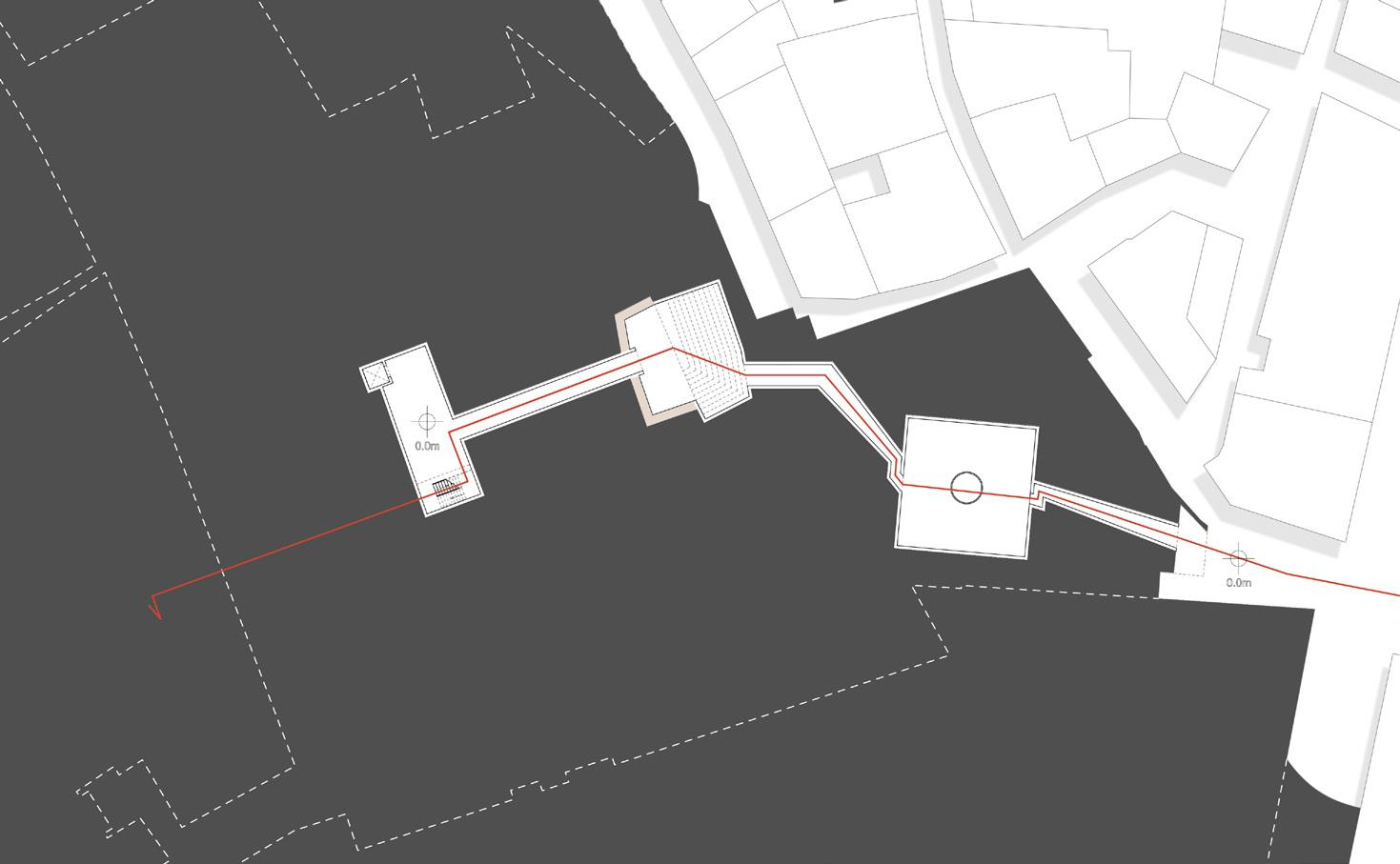
Level -3 (0m)
1 Vertical Circulation
2 Roman Cistern Room
1 3 2 1 2 3
3 Cone Room
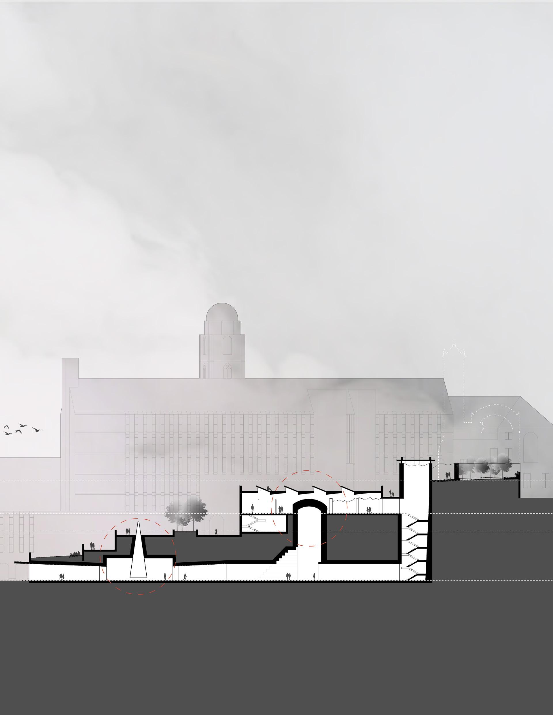
UNDERNEATH
Tunneling underneath the site completely, a long volume leads you deep into the side of the mountainous city of Genoa until you ascend into the historic ruins above. A middle gallery space is dedicated to preserving the art of Frescos.
18.00m 12.00m 8.00m 0.00m
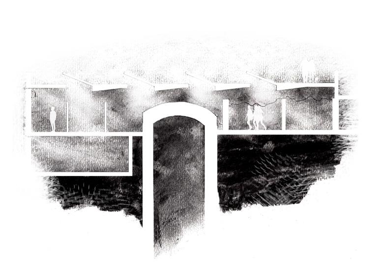
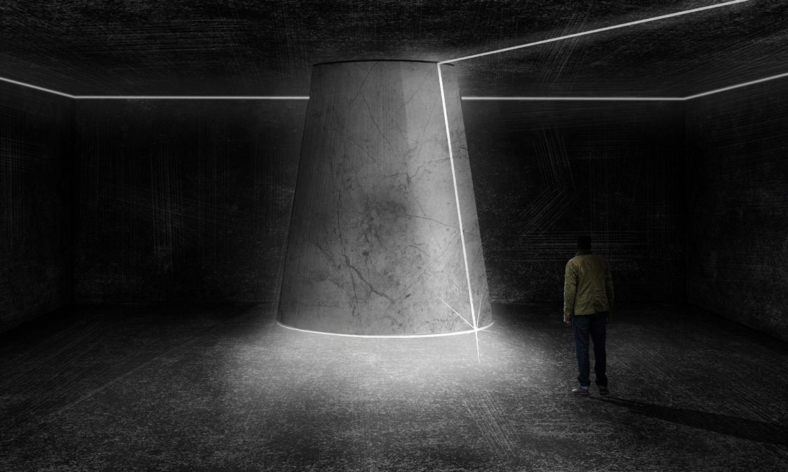

The first stop in the underground volume, an alabaster cone filters light from the surface into the dark underneath.
The second stop in the underground volume, an existing Roman cistern has been converted into and interior light exhibit showcasing the ruins.
41
Cone light detail
Cistern light detail
Cone perspective
Cistern perspective
CINEMA HOUSE
Los Angeles, CA
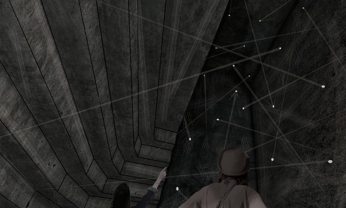
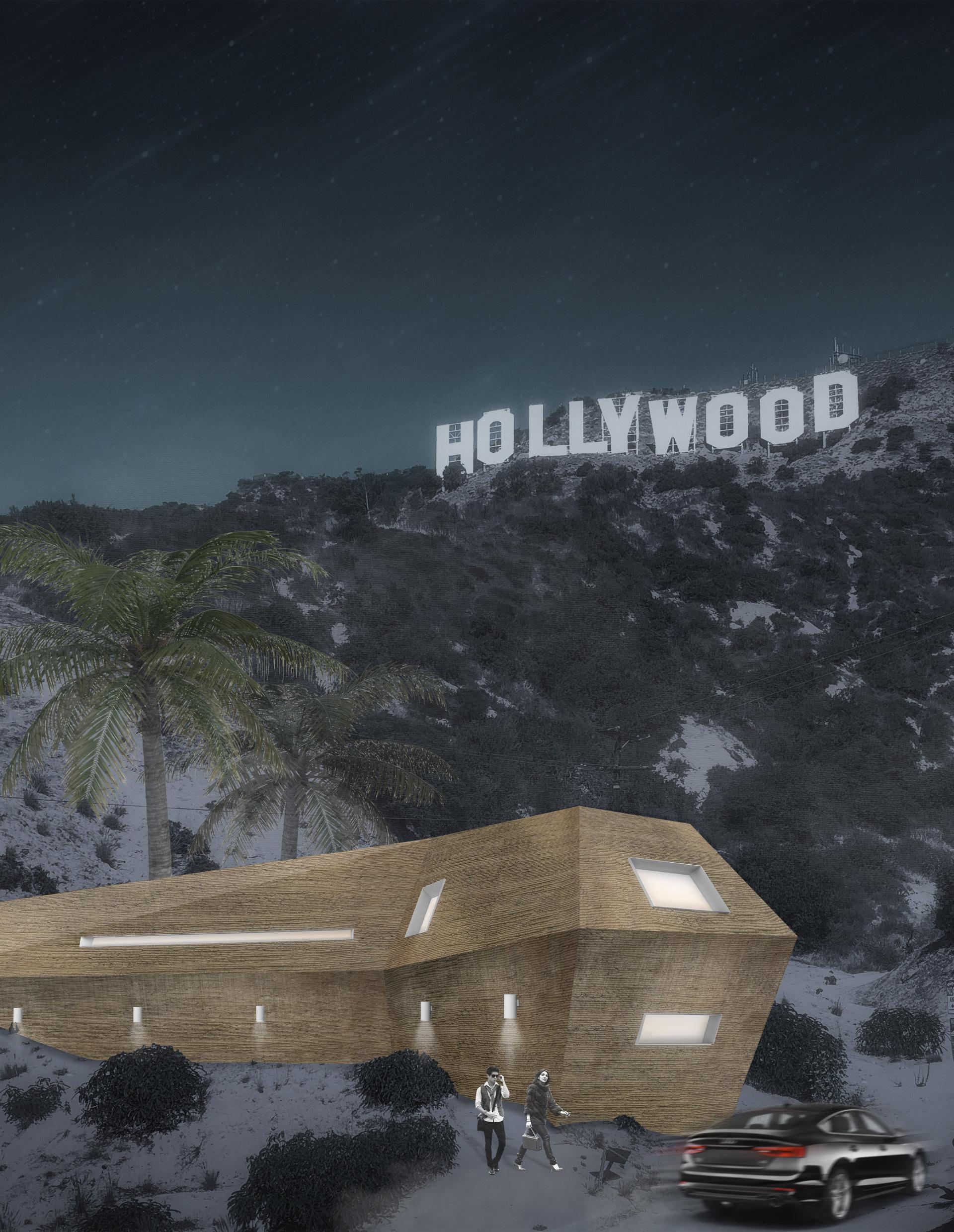
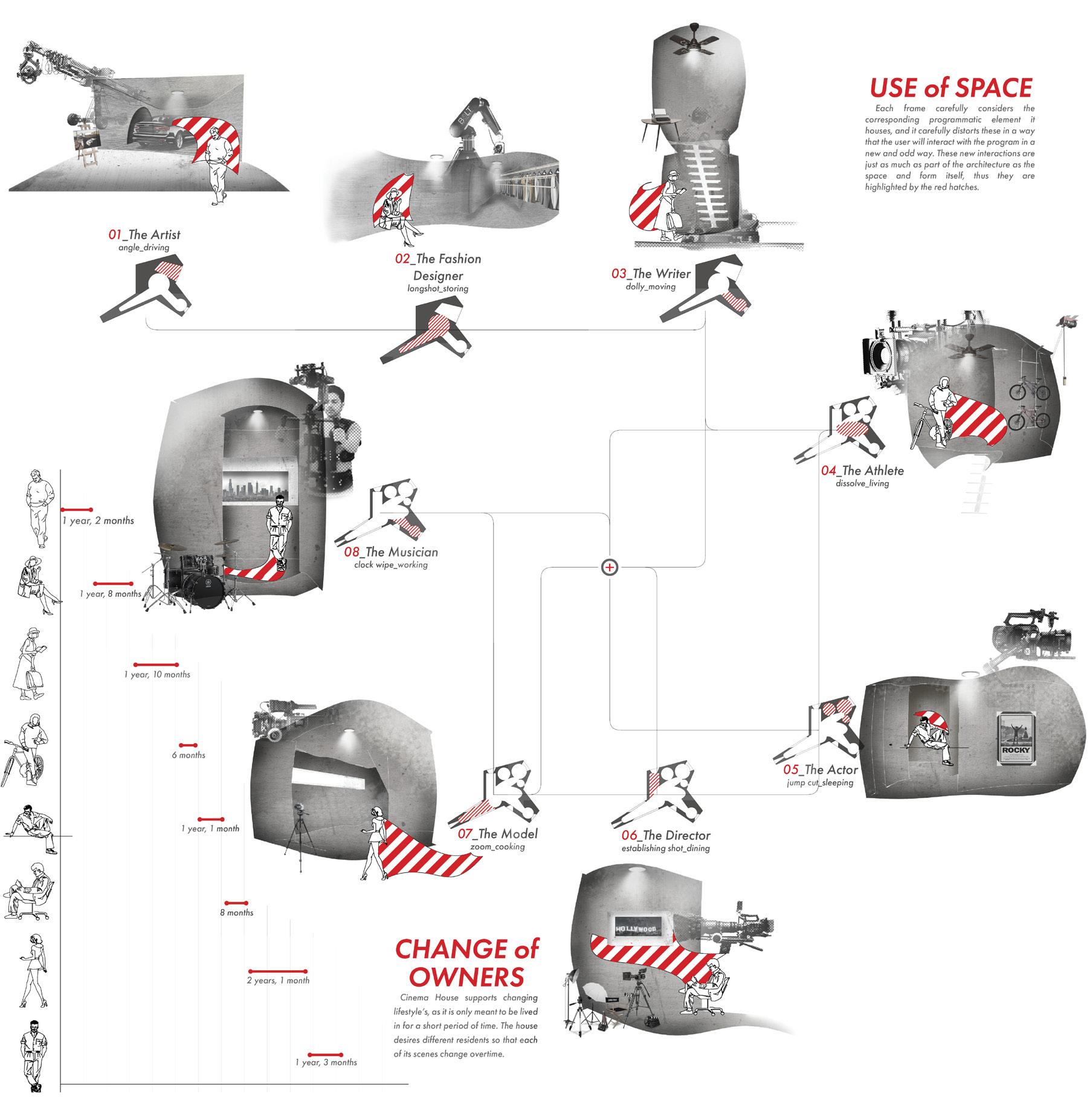
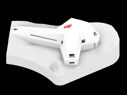
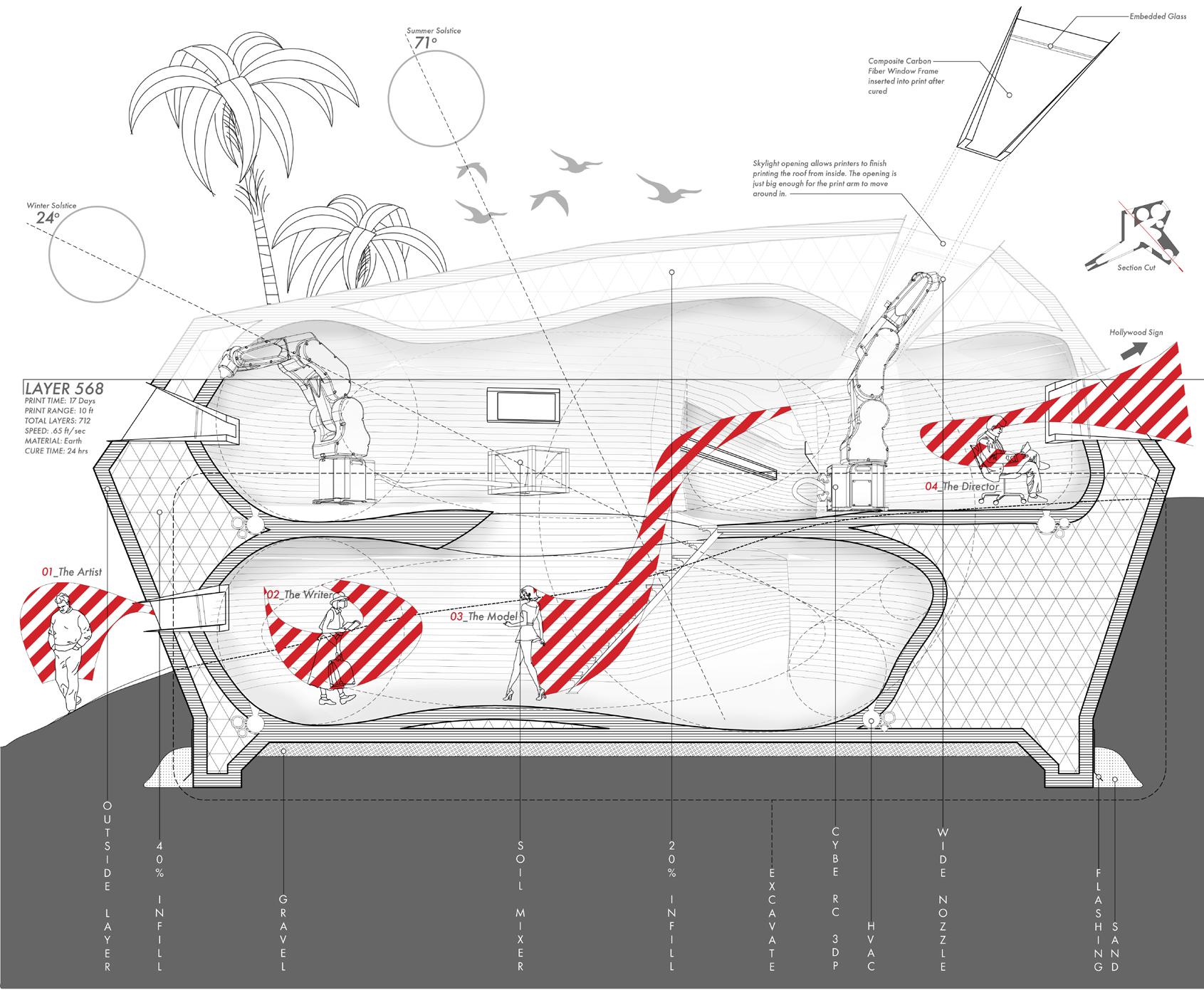
Cinematography has shaped the culture and economy of Los Angeles for over one hundred years and it will continue to do so. Utilizing the idea of Promenade Architecture, cinema house produces a cinematic experience as the user moves through the house in a series of sequential “frames”. These frames are designed using terms from film techniques. Each space or “frame” allows for an interaction with a different programmatic element. Each frame carefully considers the corresponding programmatic element it houses, and it carefully distorts these in a way that the user will interact with the program in a new and odd way. These new interactions are just as much as part of the architecture as the space and form itself. The house is also designed to be 3D printed from earth.
Prof. Hecker
Complted: Spring 2020
- 2020 HERE & NOW Housing Competiton Entry
43
44
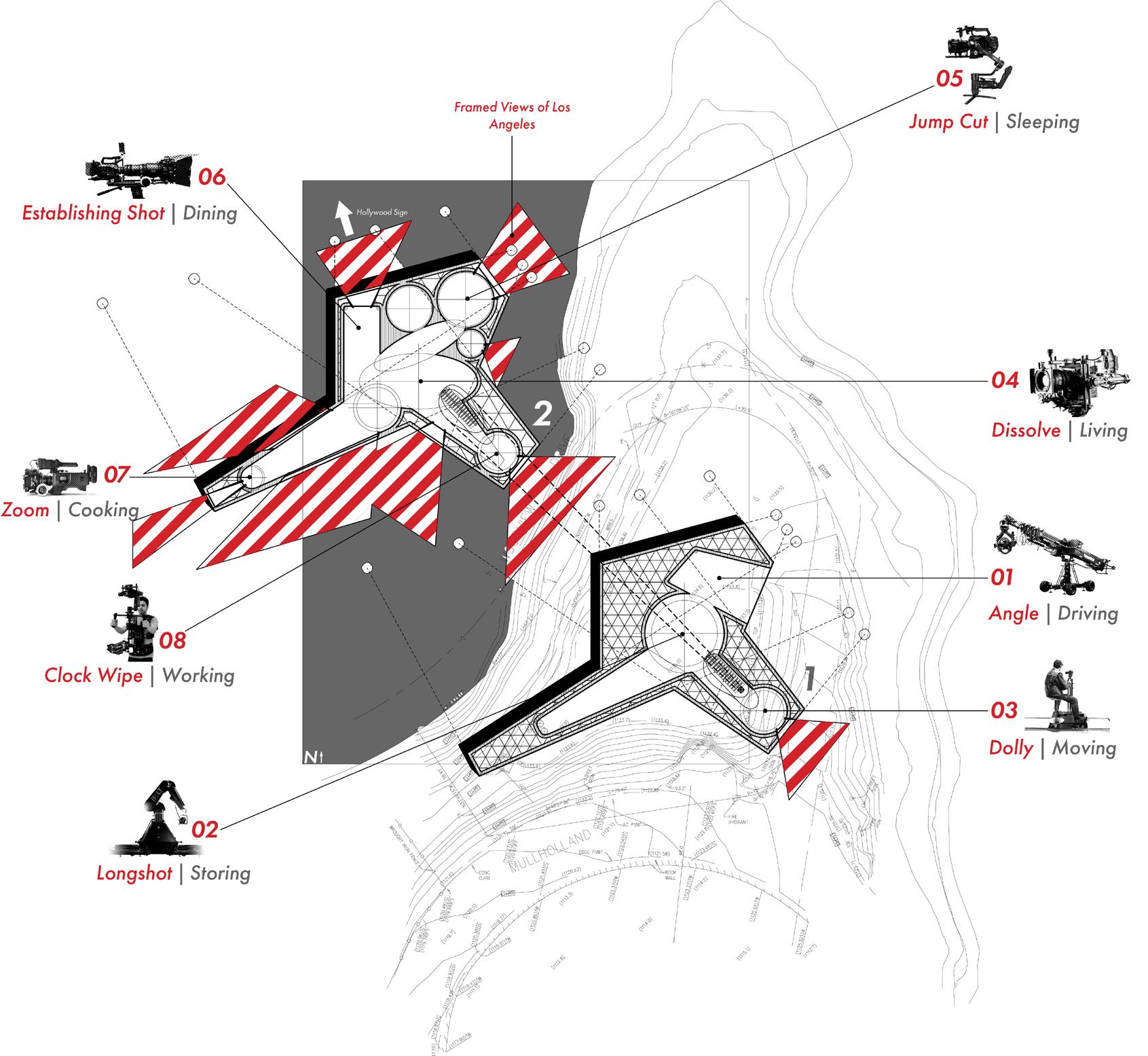
CINEMATIC SEQUENCE
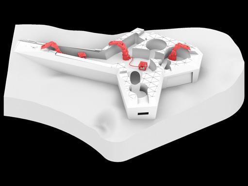
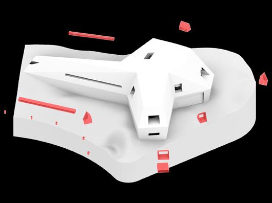
Cinema House supports changing lifestyle’s, as it is only meant to be lived in for a short period of time. The house desires different residents so that each of its scenes change overtime. These new interactions are highlighted by the red hatches and they show the residents response to each space.
45

46
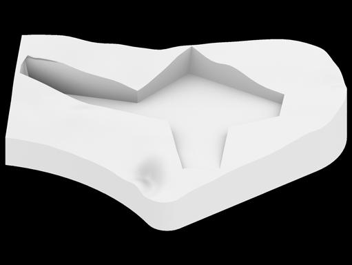
EXCAVATE
PRINT CAP INSERT
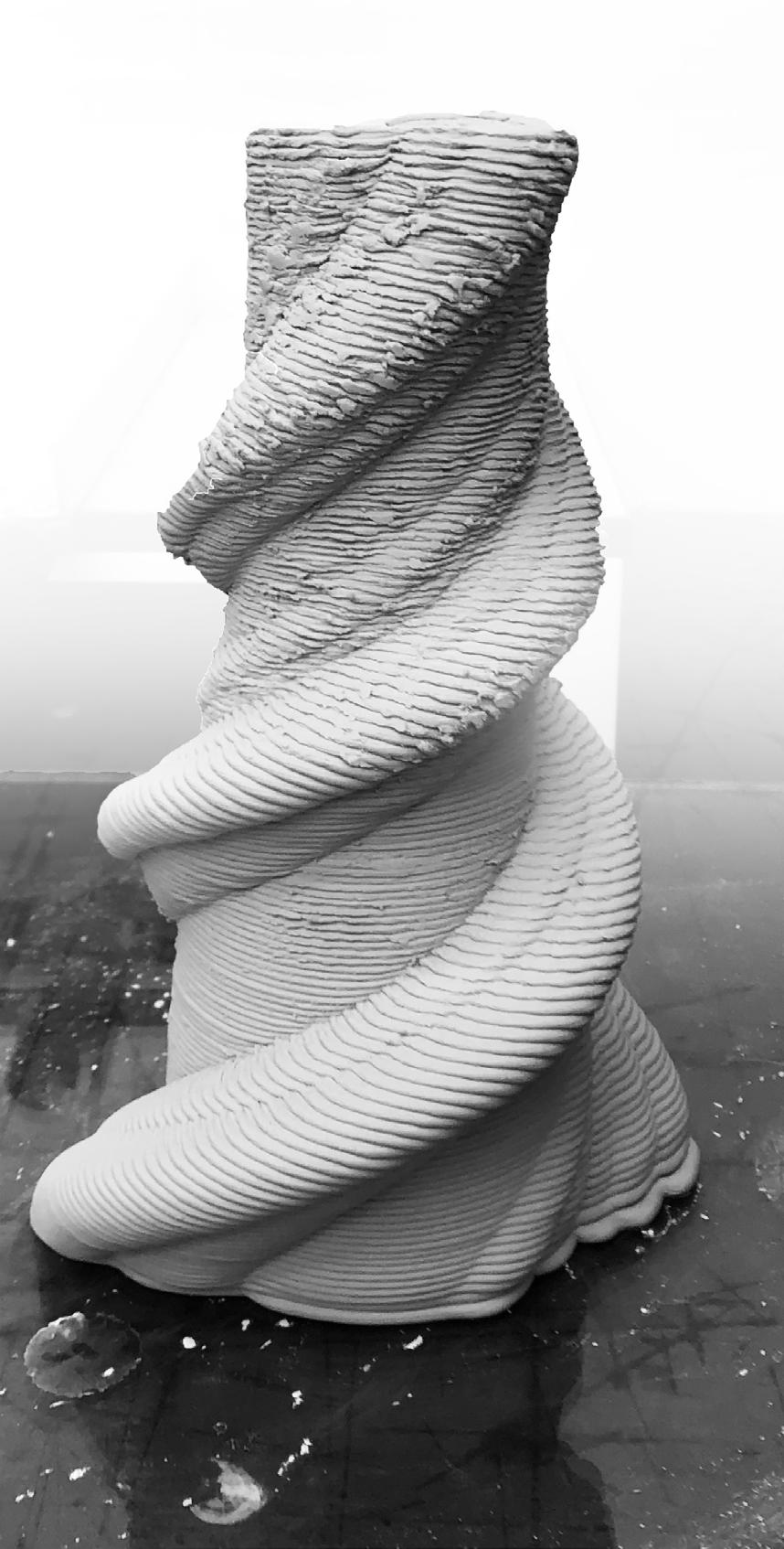
Clay 3D Print
TWO TYPES OF EARTH
The house is also designed to be 3D printed on site using the existing clay dug up from the excavation for the foundation. The printed clay is much harder and after mixing with water and other additives, it becomes stronger and more compact than it was. Voids for mechanical systems and plumbing are imbedded into the print itself.
47

48
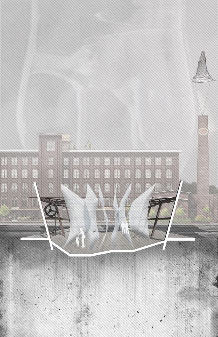
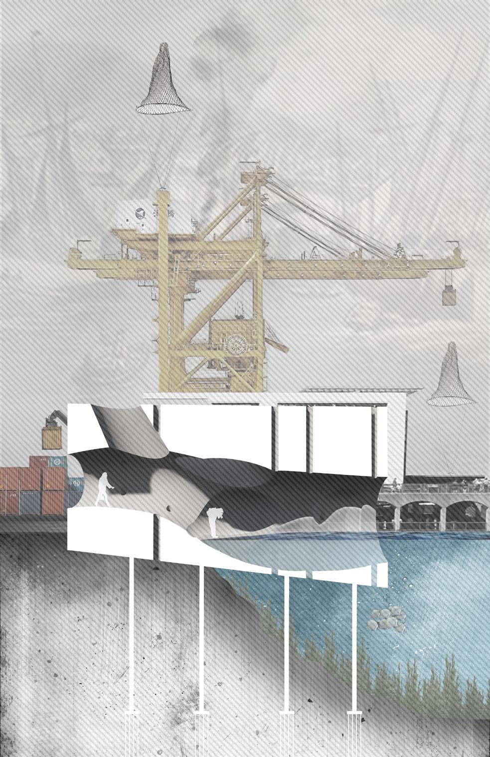
INVASION OF CHARLESTON
Charleston, SC
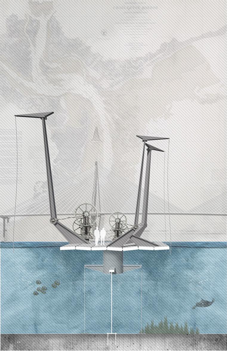

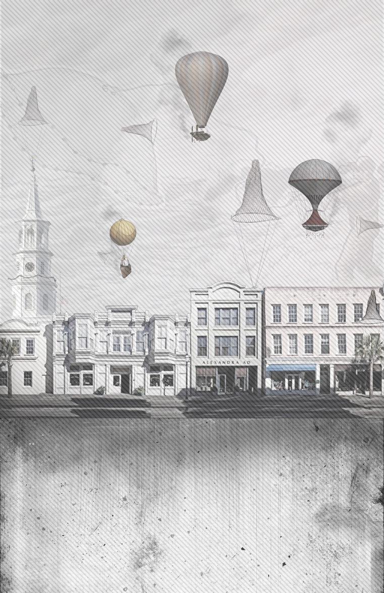
Design with respect to a narrative opens many new and surreal possibilities to architecture. Using similar collage techniques to those of James Corner, critical aspects of the city of Charleston, South Carolina were analyzed. Then, a narrative examining these aspects and addressing them through architecture further defines the project. The narrative is a tangent continuation of Paul Scheerbart’s science fiction novel Lesabéndio. An allegory is offered to the city of Charleston in the midst of their struggle with accepting the dark history that occurred there, a rising sea level that threatens its way of life and an architectural stagnancy that limits its relevancy in a new time.
Prof. Ersoy
Complted: Fall 2018
- 2019 Fairy Tales Competition Entry
- Exhibited at the City Gallery in Charleston,SC
49
VESSEL
32°47’26.6”N 79°55’30.8”W
“The second of the three exhibits was an exaggeration of the sea level rising to encompass the city. The architecture was designed to embody a sponge that would accept the rising water when tides were high or when the city experienced a storm surge. When the tides were low the sponge would release the water allowing the exhibit to be walked on. Parts of the floor were made from glass, while the rest of the exhibit was fabricated from cast concrete, a material that is unyielding to water. The Pallasians wanted the form to be a familiar shape to the humans on the exterior and an unfamiliar fluid space on the interior, stating that an exhibit rooted in both land and water must be both fluid and stagnate.”
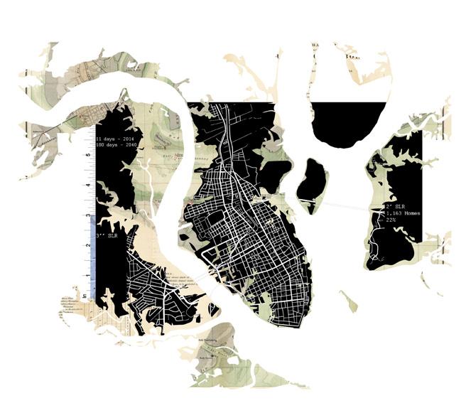
52
Flood Zone Collage
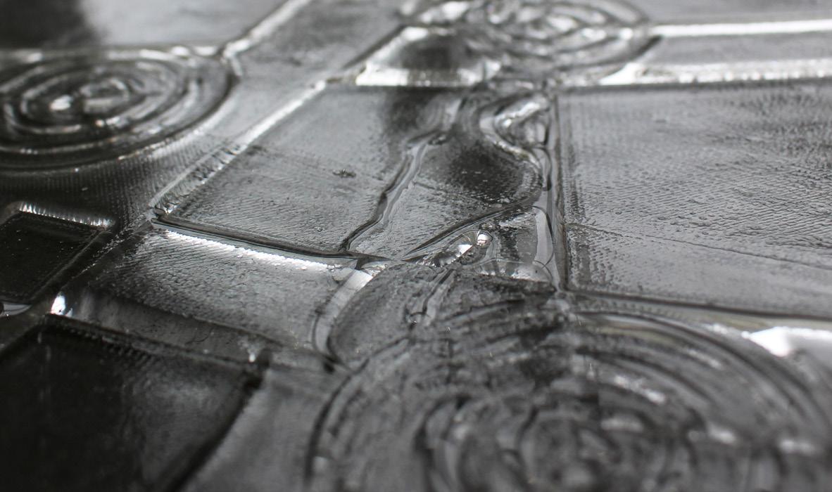
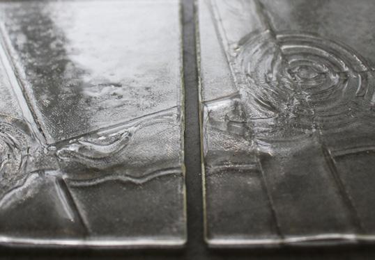

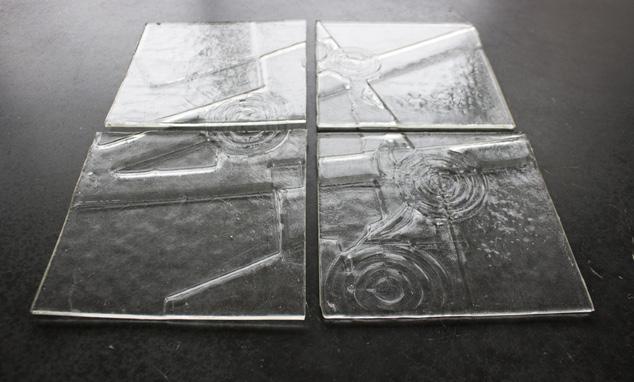
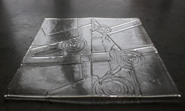
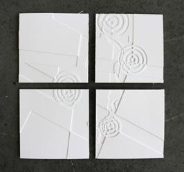
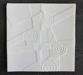
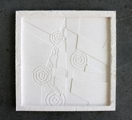
Analyzing the setting of the narrative, Gadsden’s Wharf, the site is abstracted on glass. The points of interest are made apparent by using a ripple effect. The relation with the coast line is also displayed as the wharf is surrounded by adjacent ports. The glass itself was created by firing glass tiles at fourteen hundred degrees on plaster molds. To create the molds, the site was 3D printed on tiles then cast into glycerin soap. The soap is then used to cast the plaster mold used in the kiln. The result is a glass tile that resembles liquid, contrasting the material itself.
55
LIQUID GLASS
Kiln Fired Glass Fabrication
Glass Tiles
Process Molds
Thank You