SOFT LANDING | STAGE 4
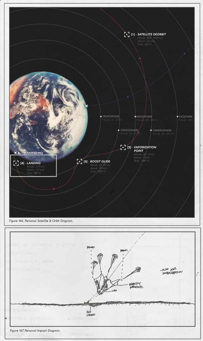
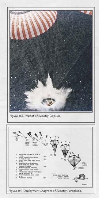
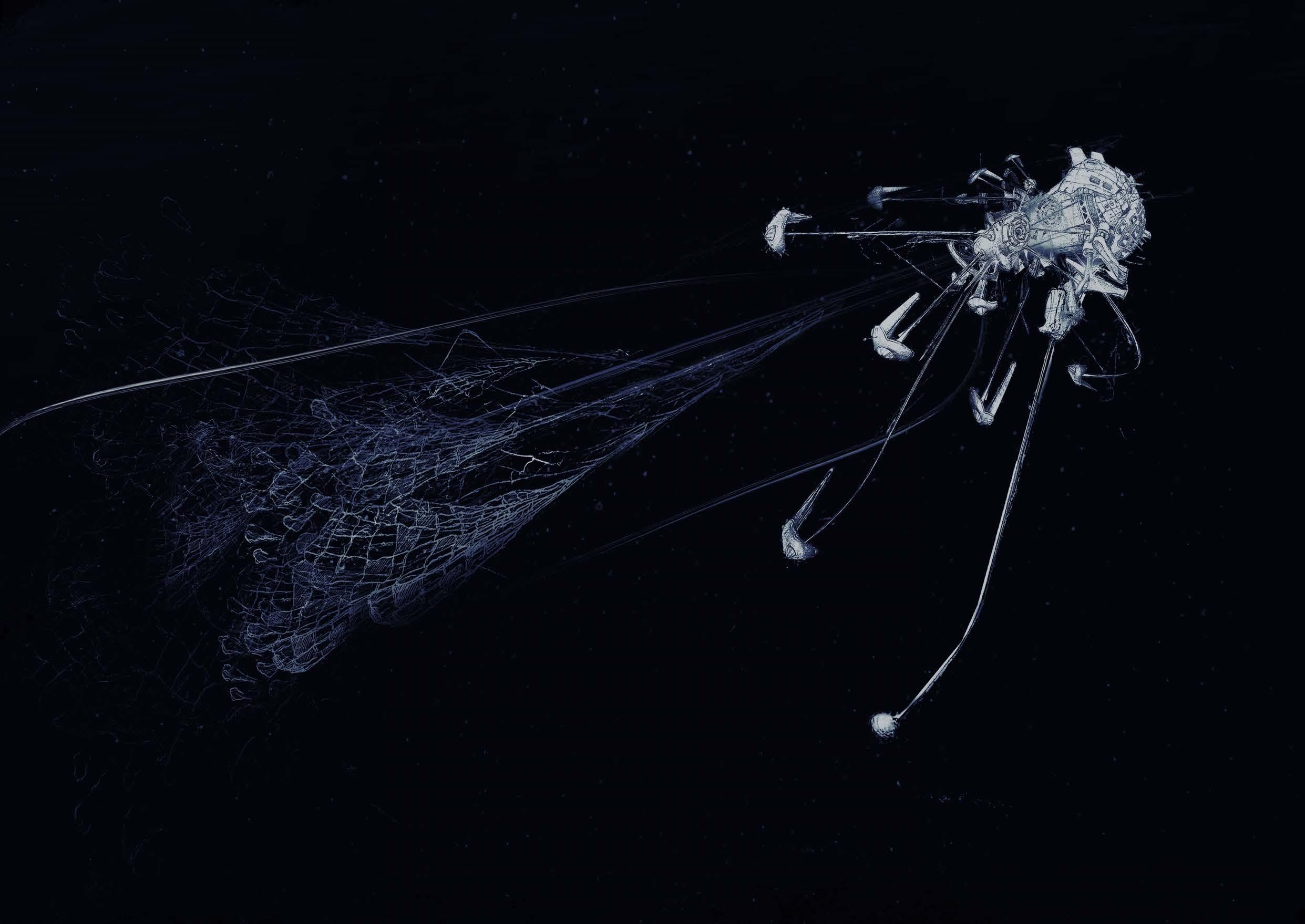
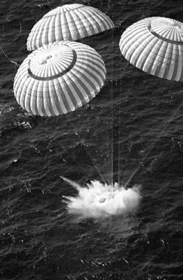
 The RemoveDERBIS satellites carry out step 1-3 prior to reentering the Earth’s atmosphere. As the final stage of soft landing, step 4 includes the deployment of parachutes as well as a series of on-water preparations.
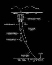
Bulletproof Vest
Dimensions: 8 x 5 cm


Weight: 2.3 g
LANDING | WATER SURFACE TENSION

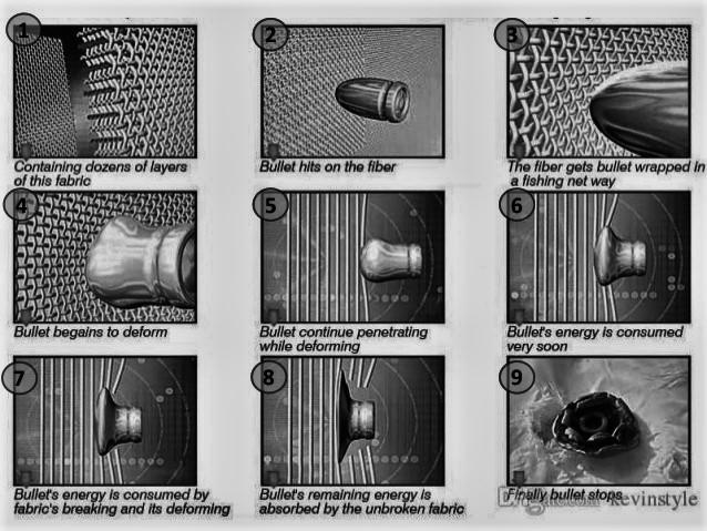
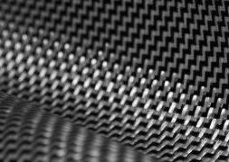
The goal is to best preserve the mass and shape of the satellites. As seen previously, bulletproof vests can deform bullets, which indicates that the graphene sheets should not be the first to contact the satellites. From the Mythbusters, we also learn that water can be as hard and as damaging as concrete when hit with a high velocity.

 Experiment 2 [Mythbusters]
Experiment 3 [Mythbusters]
Experiment 1 [Mythbusters]
Experiment 2 [Mythbusters]
Experiment 3 [Mythbusters]
Experiment 1 [Mythbusters]
SHEET PREPARATION | WATER SURFACE TENSION
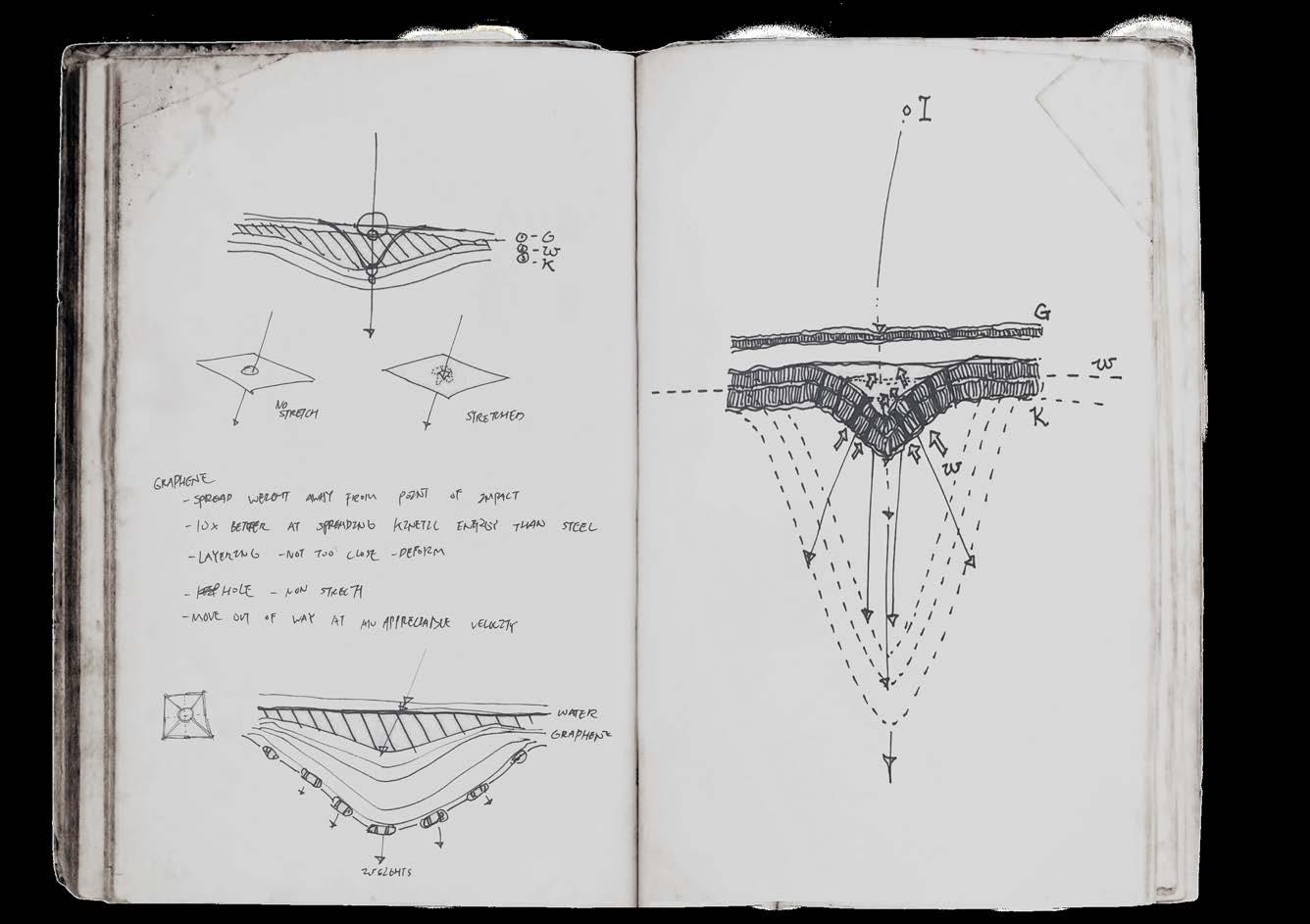
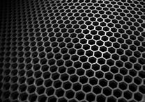
 Therefore, the sheets must be pulled down just before the landing, as the pulling of the sheet will aerate the water with a temporary pocket of air bubbles for the debris to land on with little to no water surface tension.
SHEET PREPARATION | SEA ANCHOR
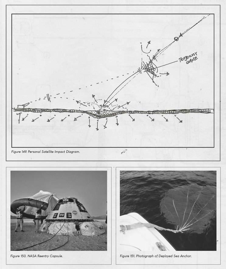
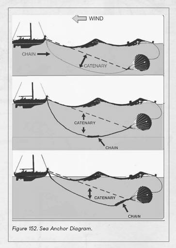 In the case that the debris does contact the sheet even after slowing down from the water, the sea anchors will prevent the constellation from capsizing.
IMPACT SEQUENCE | SEQUENCE 1
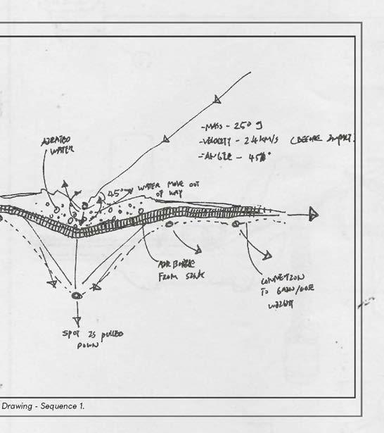
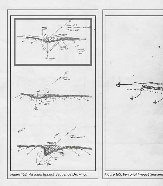
 The three impact sequences summarize the forces and elements in play.
IMPACT SEQUENCE | SEQUENCE 2
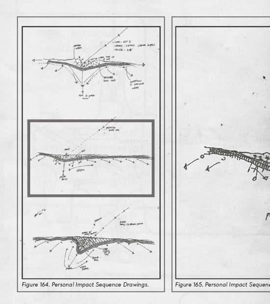

Including the satellite, the sea anchors -
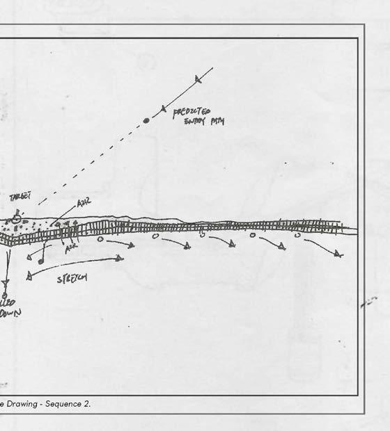
and
IMPACT SEQUENCE | SEQUENCE 3
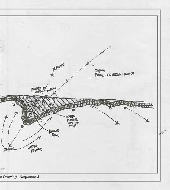
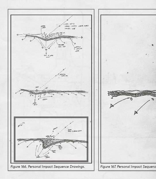 how the water can be used to trap the fragments from potential ricochet.


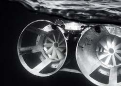
STORAGE & DISPLAY | OCEAN SURFACE INHABITATION
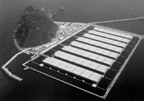
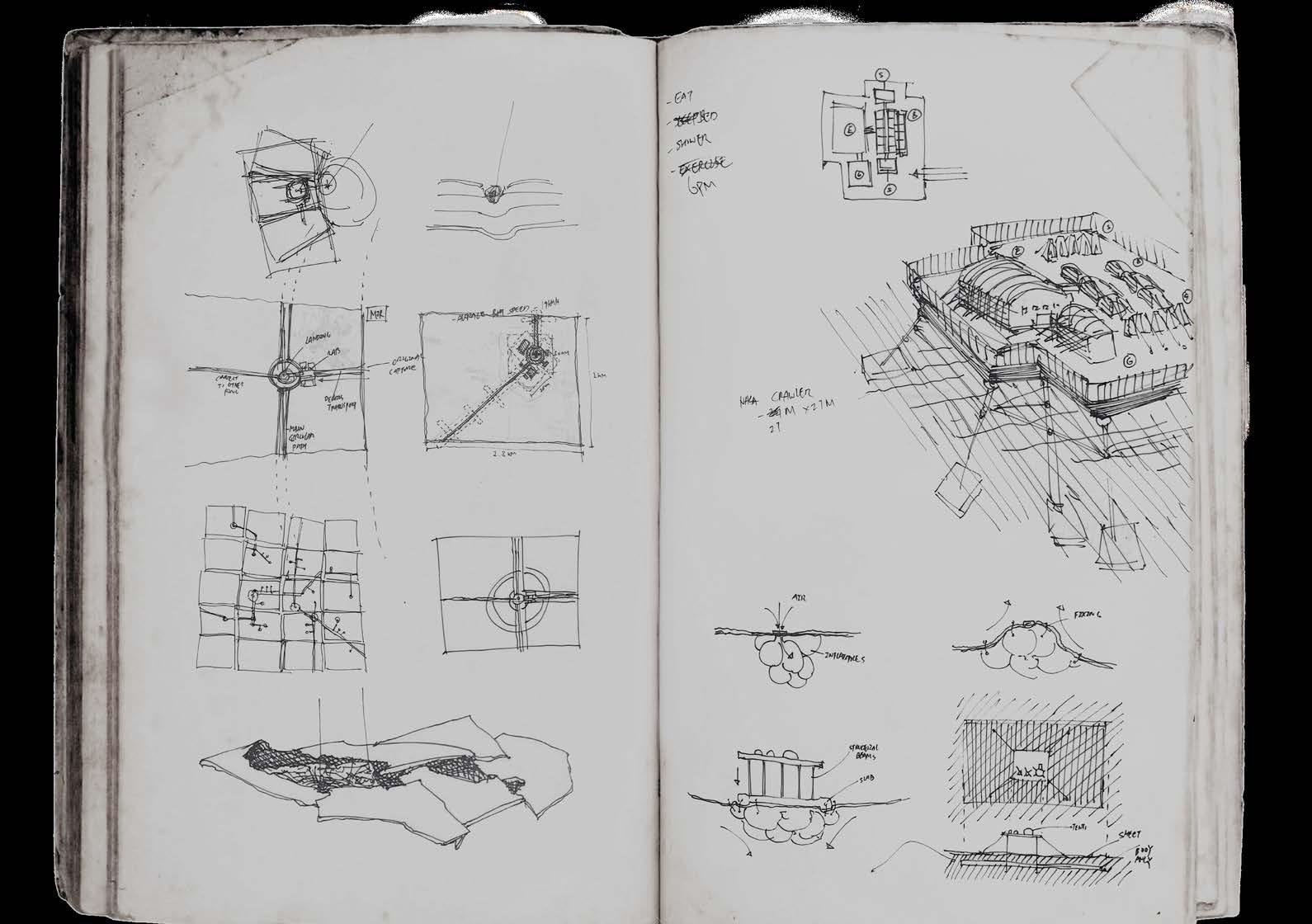
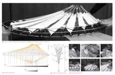
 Informed by Japanese floating energy farms, the pathways and platforms which support inhabitation is then articulated between the sheets using pontoons and columns.
Energy Farm - Japan [Armellino]
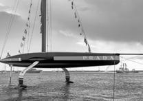
Foil Arms - Admiral’s Cup [Team Italy]
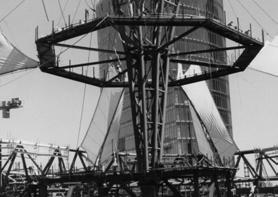
Ocean Construction [NASA]
Informed by Japanese floating energy farms, the pathways and platforms which support inhabitation is then articulated between the sheets using pontoons and columns.
Energy Farm - Japan [Armellino]
Foil Arms - Admiral’s Cup [Team Italy]
Ocean Construction [NASA]
NEMO SPACE ARCHIVE | GROWTH
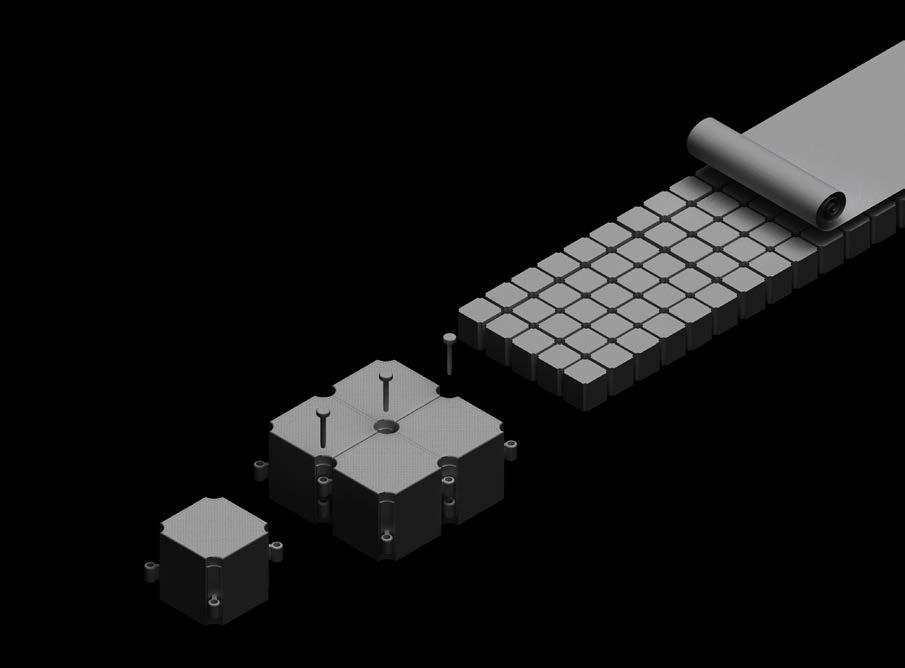
Thanks to the customizable nature of pontoons, the
will be able to grow while adapting to the necessities
different
IMPACT | RIPPLE EFFECT


 Underneath the bulletproof skin, the inhabitable pontoon structures are safe from direct hits but are still subjugated to harsh conditions given the current and ripples that can be generated by nearby captures.
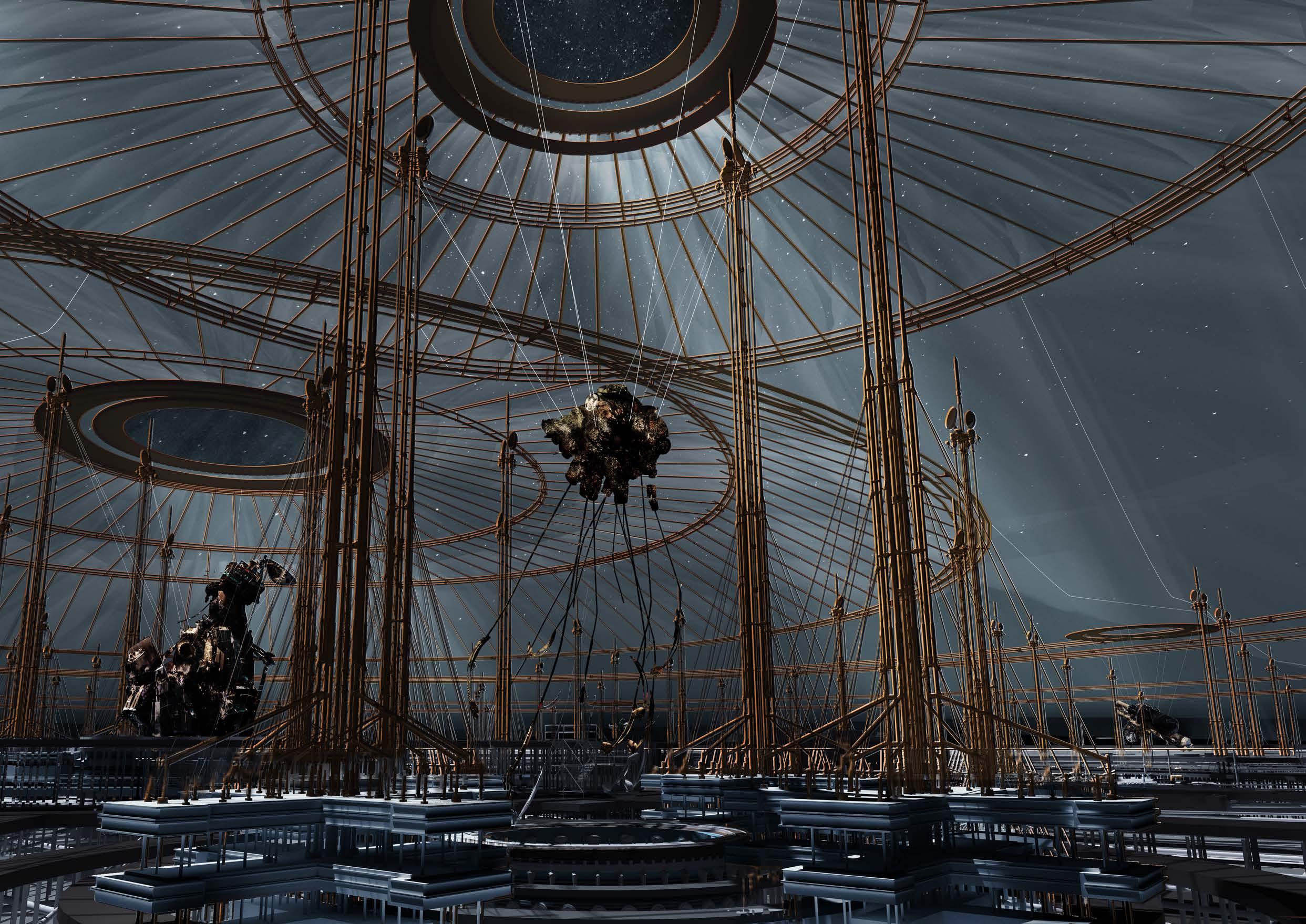
INHABITATION | STRUCTURAL RINGS


In order to keep things in place, a number of circular trusses informed by the Sonic Centre will surround the fragment to provide stability.
 Energy Farm - Japan [Armellino]
Foil Arms - Admiral’s Cup [Team Italy]
Ocean Construction [NASA]
Energy Farm - Japan [Armellino]
Foil Arms - Admiral’s Cup [Team Italy]
Ocean Construction [NASA]
RENEWABLE ENERGY | HYDROTHERMAL VENT


 A large number of tensioning cables will then hold the truss rings in place, as well as to carry any underwater components of the building.
RENEWABLE ENERGY | HYDROTHERMAL VENT

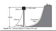


As studied in the tech report, the facilitation of the satellites will take place above hydrothermal vents. With the help of the offshore thermal energy conversion systems, the building will be able to extract energy from the ocean.
RENEWABLE ENERGY | HYDROTHERMAL VENT


The diagram demonstrates the placement of the OTECs in relation to the vents. The OTECs generate energy through the difference in water temperature between the ocean surface and the thermal vents.
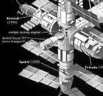
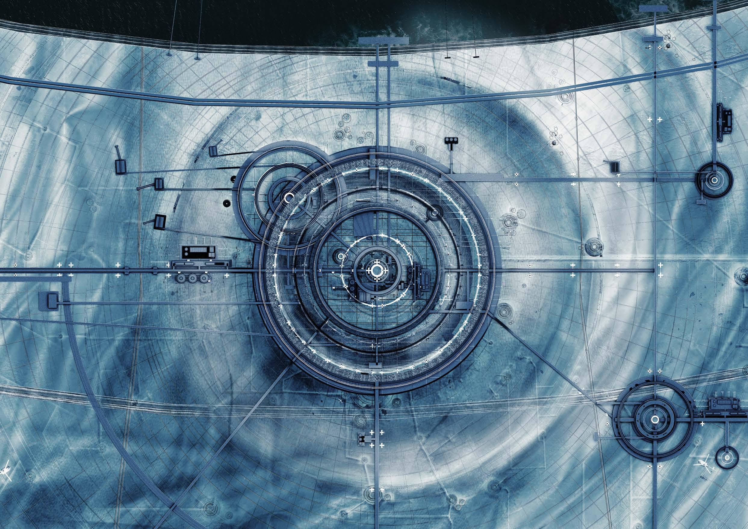
SHEET A-82 | MIR STATION

In correspondence to the section, the plan highlights the key spaces of the Mir Outpost which is set to complete in the year 2024. The key spaces include the main debris facility at the center of the rings, the energy facilities to its left as well as the other smaller fragments around and their designated loading docks.
MIR STATION | TRANSPORT & STORAGE FACILITIES


VO70-291353-033-008283
Date. 21-03-2001
Ground point. 42.12° North. 12.52° East.
Orbital speed. 4.760 km/s. 17137 km/h.
Altitude. 36,000 km
Time. 05:23:14 UTC.
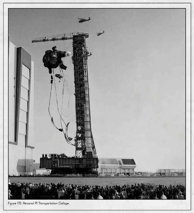
On February 2nd of the year 2024, during the 34th solar cycle at approximately 5:23 universal time, the mission to capture the international space station is commenced with the deployment of 6 removeDEBRIS satellites.
VO70-291353-033-008283
Date. 21-03-2001
Ground point. 42.12° North. 12.52° East.
Orbital speed. 4.760 km/s. 17137 km/h.

Altitude. 36,000 km
Time. 05:23:14 UTC.
At an altitude of 368 kms with a orbital speed of 4.7km/s, the ISS was officially secured after 3 hours of micro-adjustments.VO70-291353-033-008283
Date. 21-03-2001
Ground point. 42.12° North. 12.52° East.
Orbital speed. 4.760 km/s. 17137 km/h.
Altitude. 36,000 km
Time. 05:23:14 UTC.
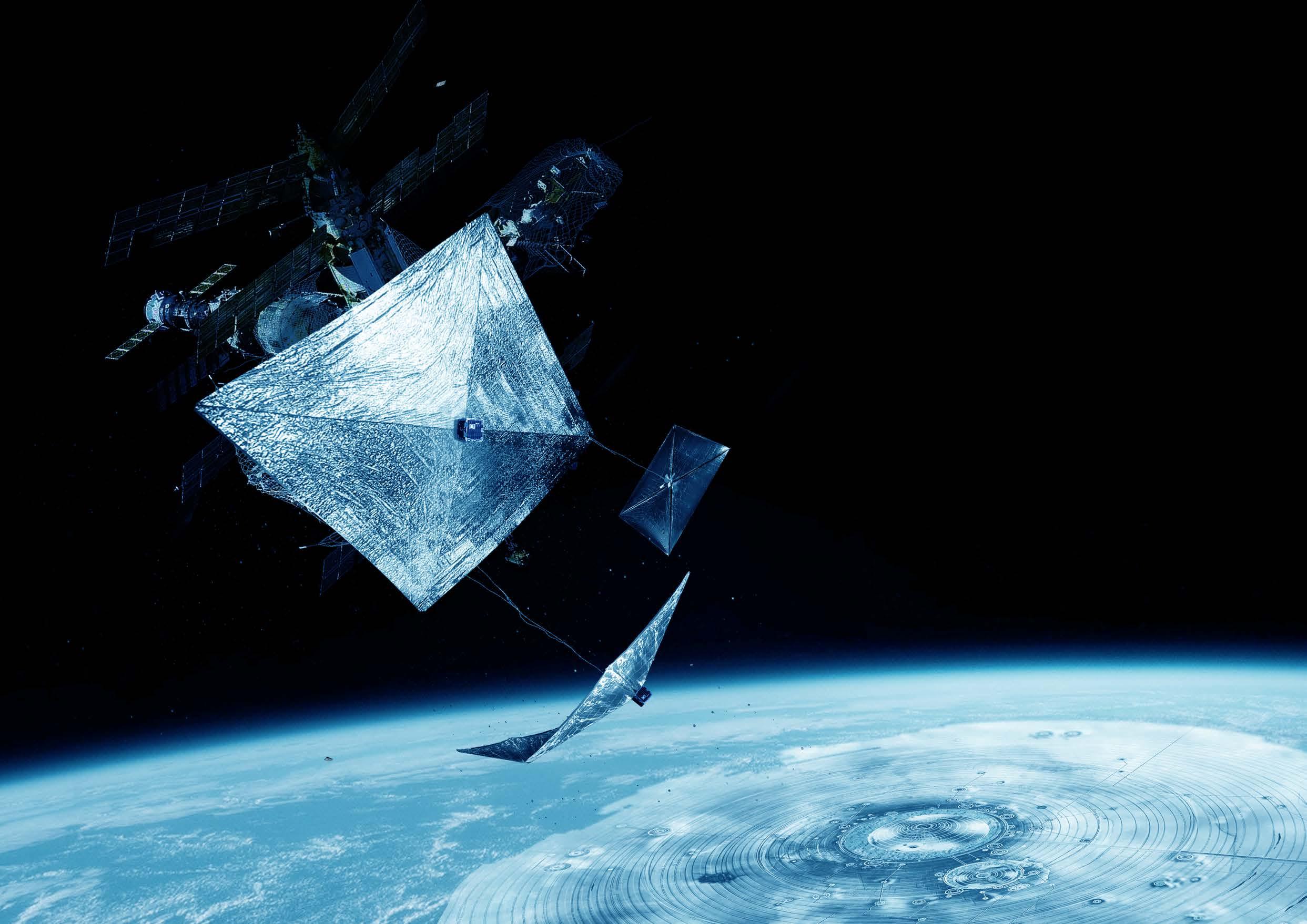
In accordance with the stages of soft landing as previously mentioned, the removeDEBRIS satellites deployed their solar sails approximately 45minutes after the deorbit. The solar wind of this particular solar cycle has been calculated to be able to sail the ISS in the direction of the Nemo Constellation.
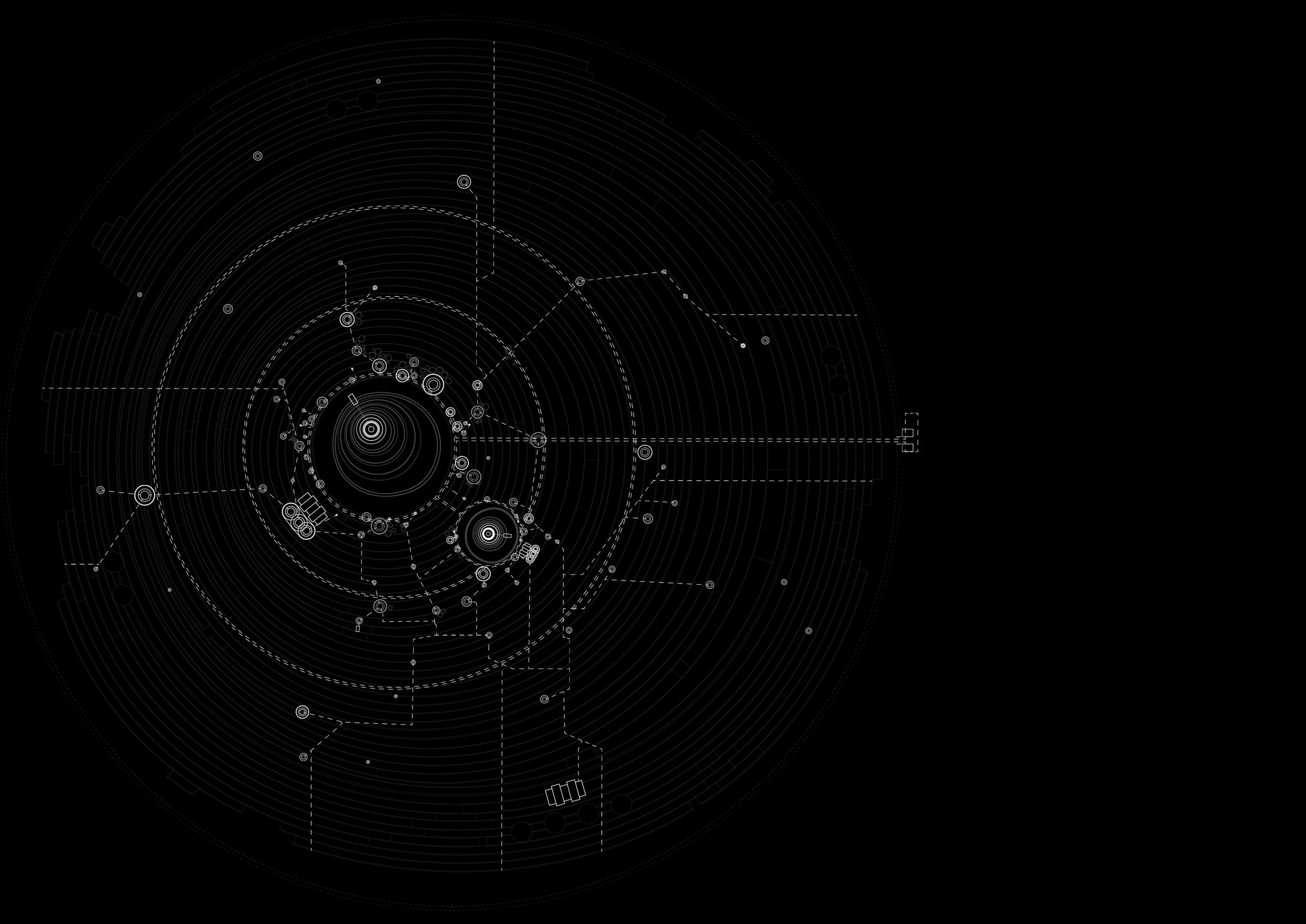
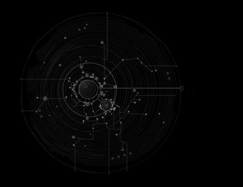
NEMO ARCHIVE | MASTERPLAN
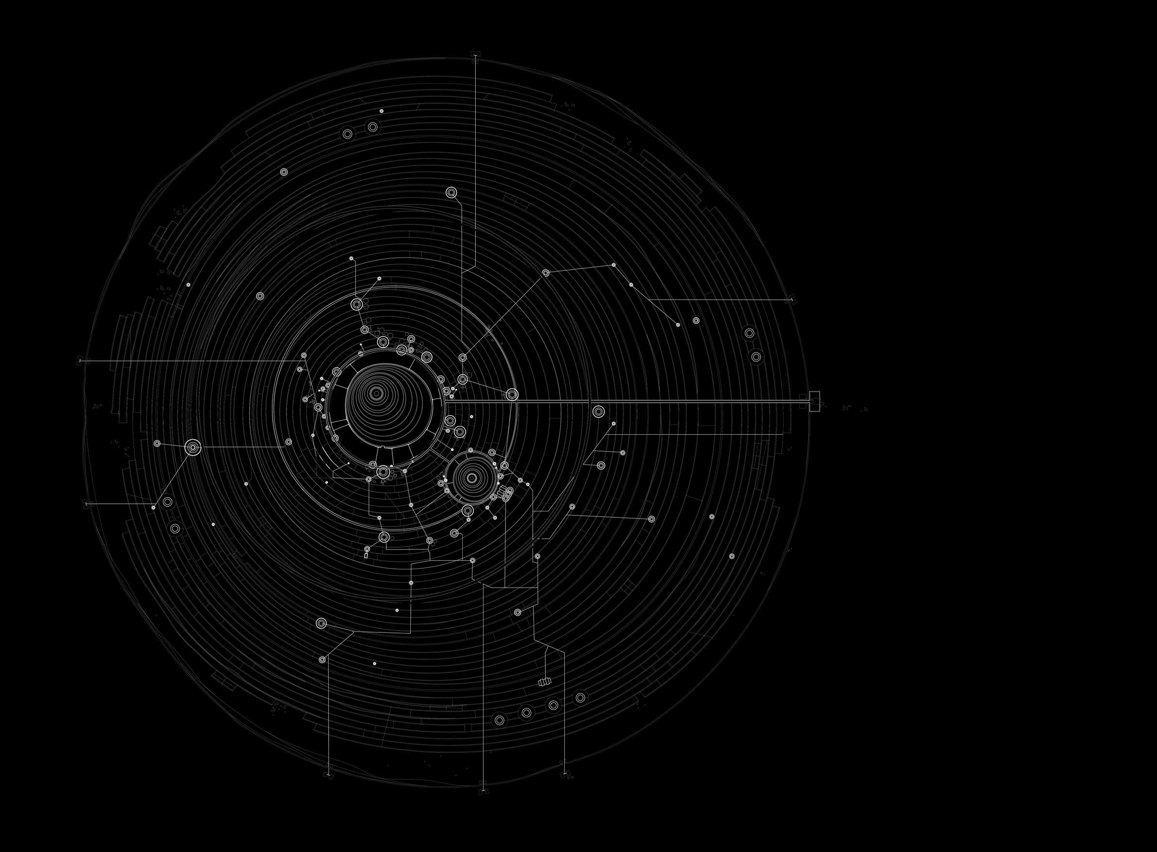
The

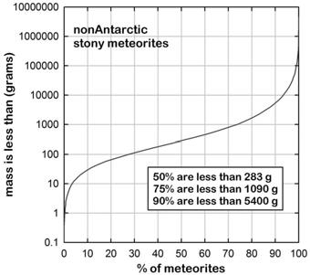
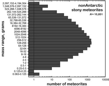
The reason for its size is simple. An average 500 meteorites reach the surface of the Earth each year, but less than 10 are recovered. This is because most fall into the ocean and statistically, having a 1million km2 surface area will guarantee the capture of at least one meteorite annually, given the total surface area of the Earth.
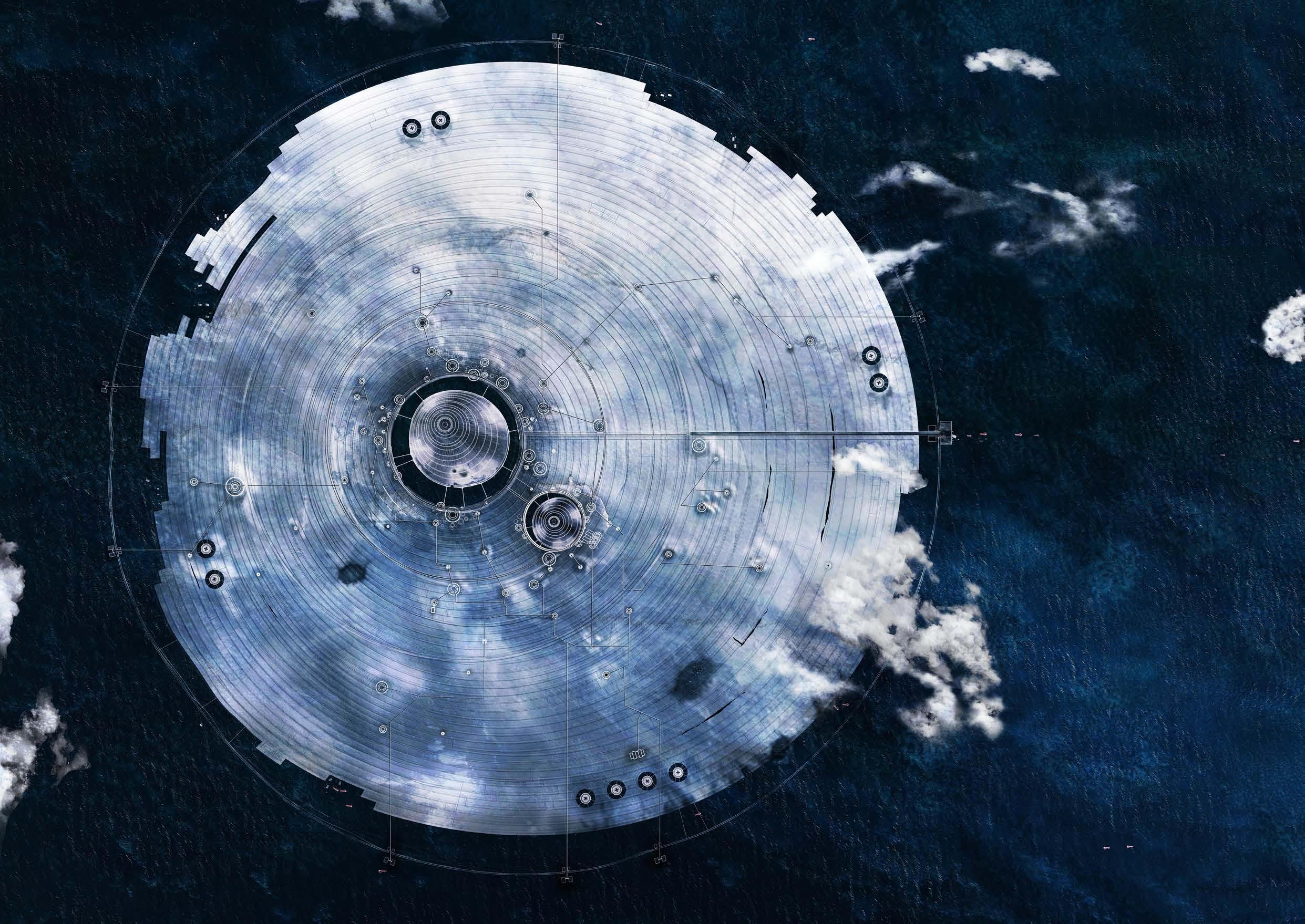
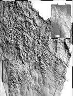
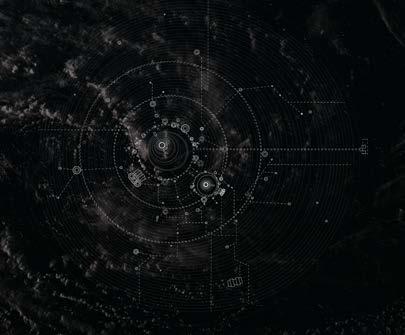
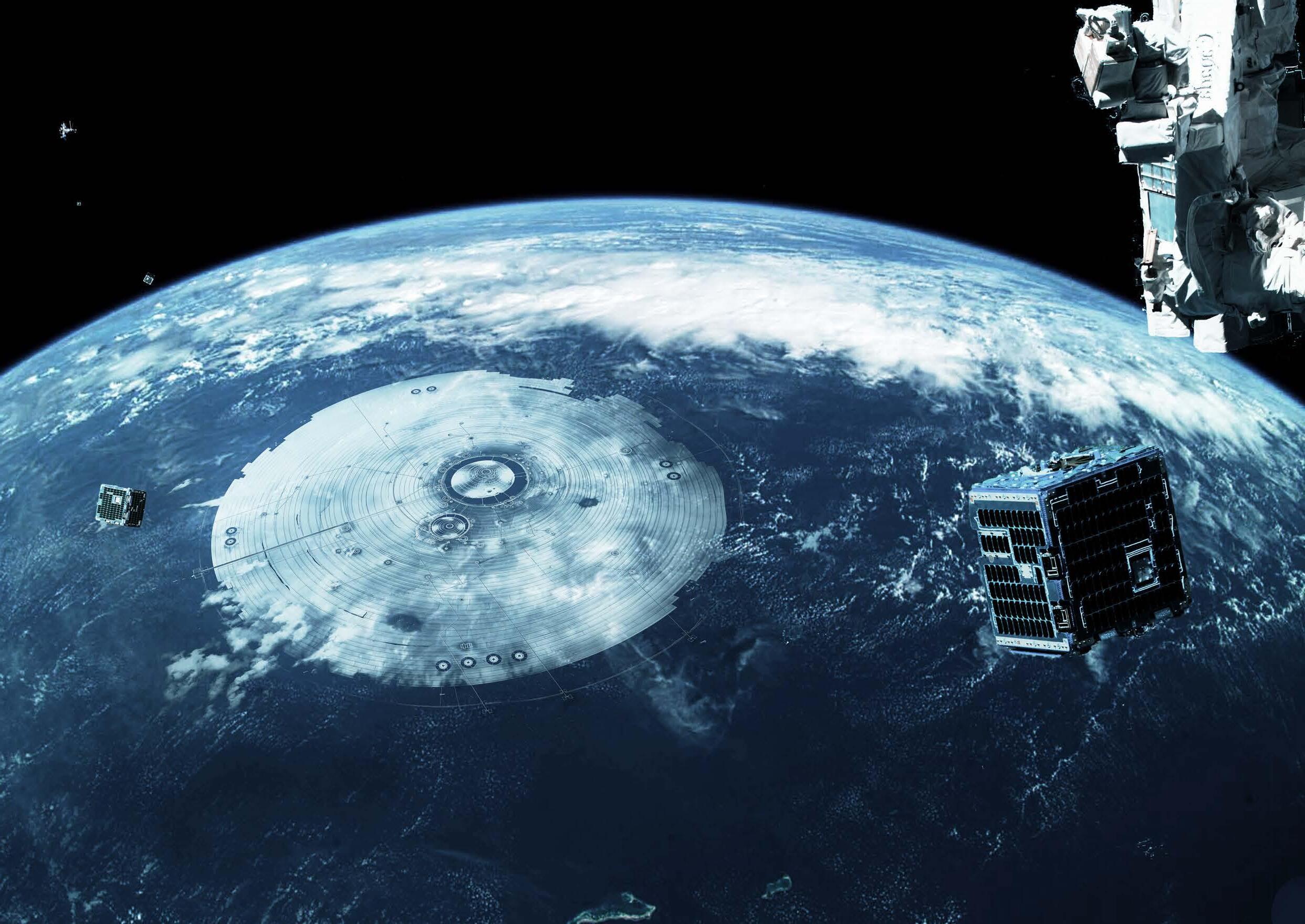
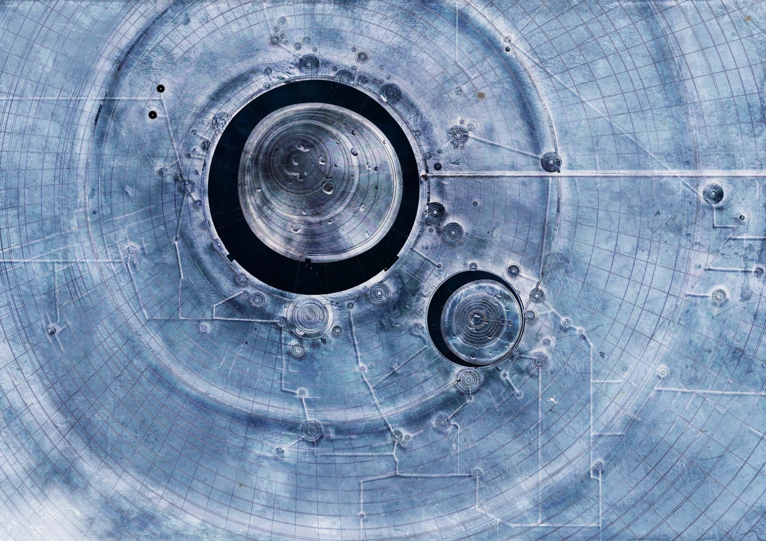
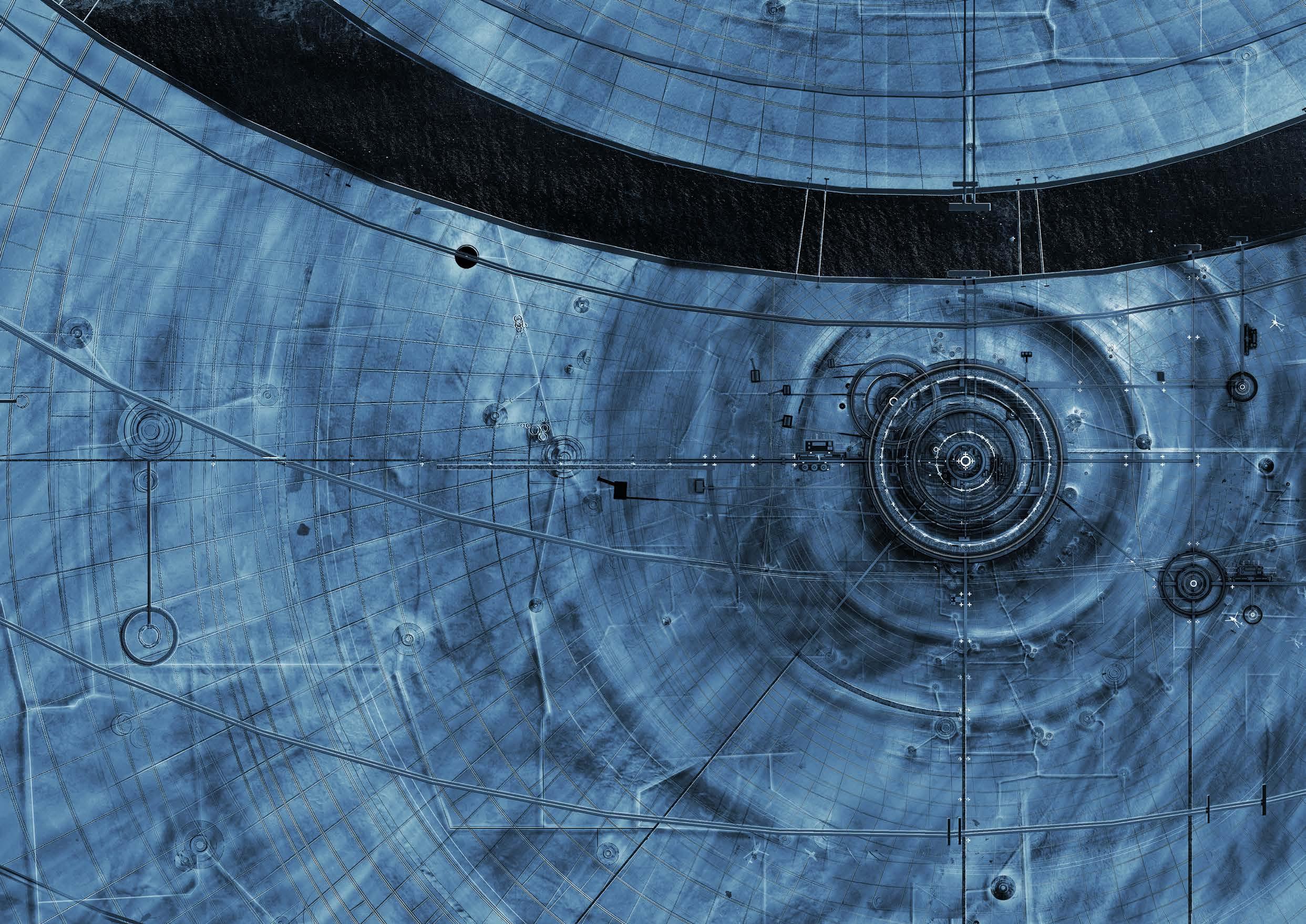
NEMO ARCHIVE | DETAIL

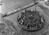
As seen in the aerial shot provided by NASA. Mir Outpost is located to the South of the Main DebrisCapture Net and West to the secondary DebrisCapture Net. These large circular stand-alone graphene vests are designated impact points for controlled reentries.
VO70-291353-033-008283
Date. 21-03-2001
Ground point. 42.12° North. 12.52° East.
Orbital speed. 4.760 km/s. 17137 km/h.

Altitude. 36,000 km
Time. 05:23:14 UTC.
The DebrisCapture Nets are patted with extra layers, making controlled reentries even safer for surrounding structures. Just after midnight, the ISS struck at an angle of 34 degrees with a velocity of 1.2km/s, well within the protective range of net.
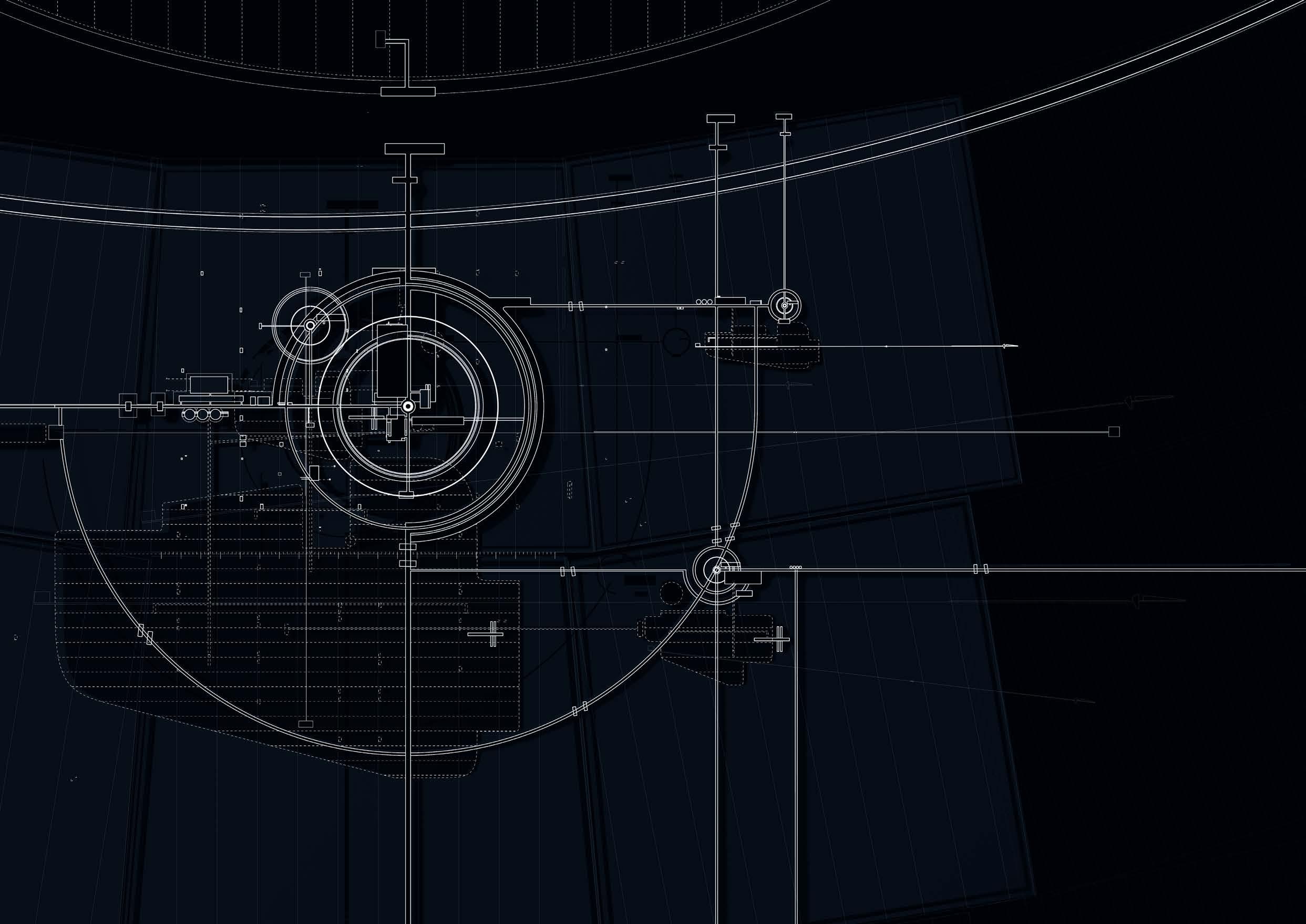
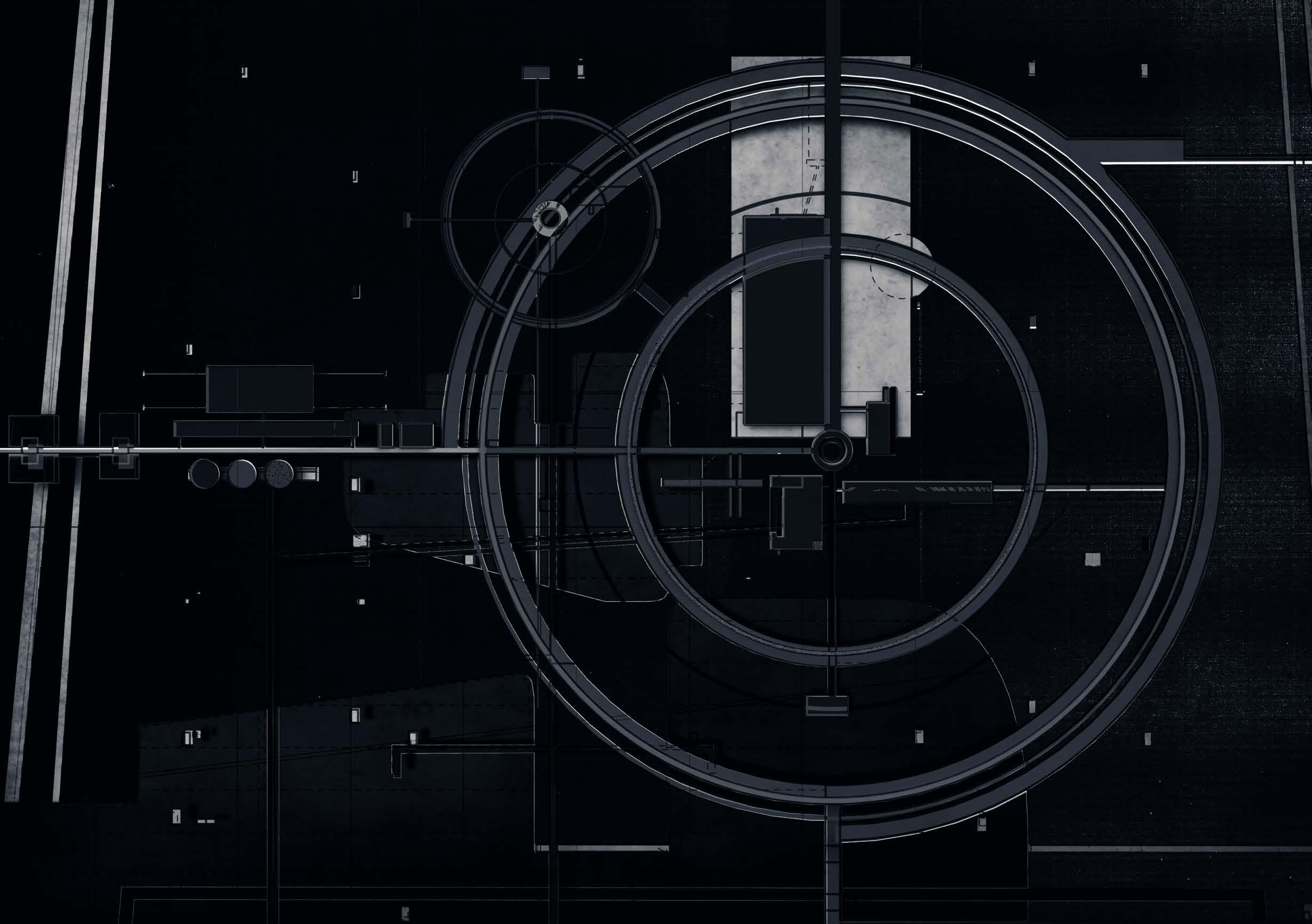
SHEET A-82 | MIR OUTPOST
Zooming into sheet A-82 which has a dimension of 1 by 1 km. Its key components include the rings of pontoon paths surrounding the center, as well as the hangars which house transportation units.
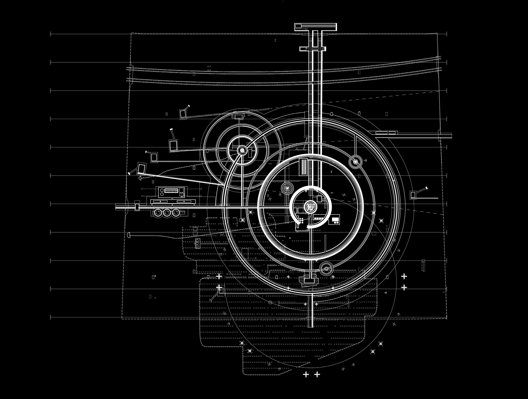
SHEET A-82 | MIR OUTPOST
Based on the blueprints and aerial photos shown previously, researchers have pieced together some more detailed zoom ins of Mir Outpost.

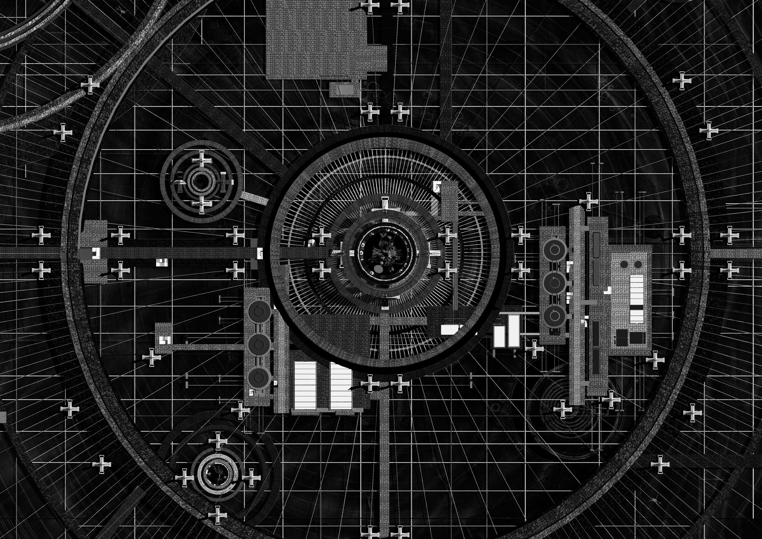
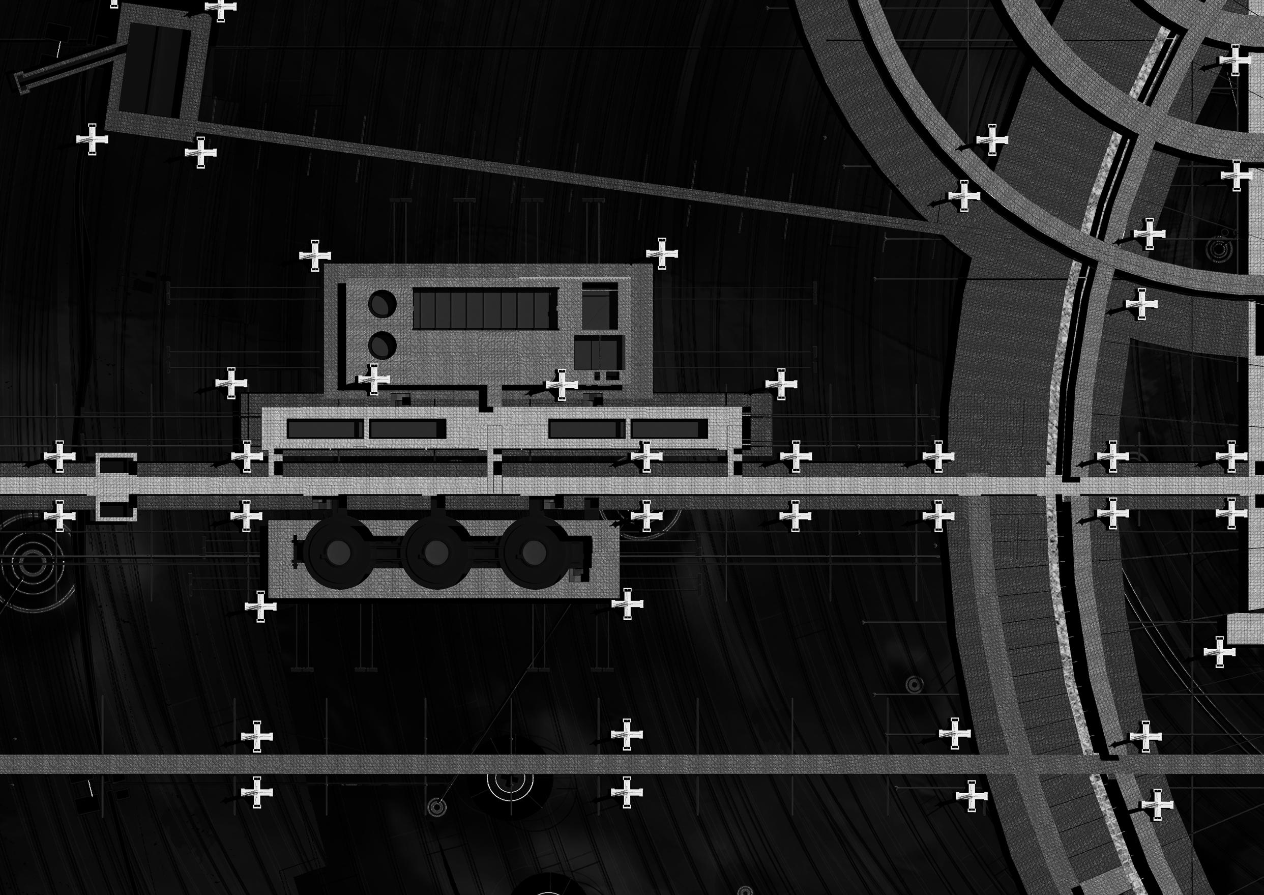
MIR OUTPOST | DEBRIS FACILITATION
The first digitally generated plan provides a closeup view of the central fragment and the facilities surrounding it, including energy storage tanks, crawler hangars, and tents/living modules.
MIR OUTPOST | ENERGY STATION
Following the first, the second digitally generated plan looks to the west of the fragment and shows the energy facilities as well as the helicopter hangars.
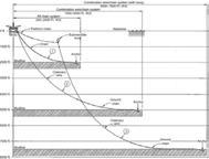
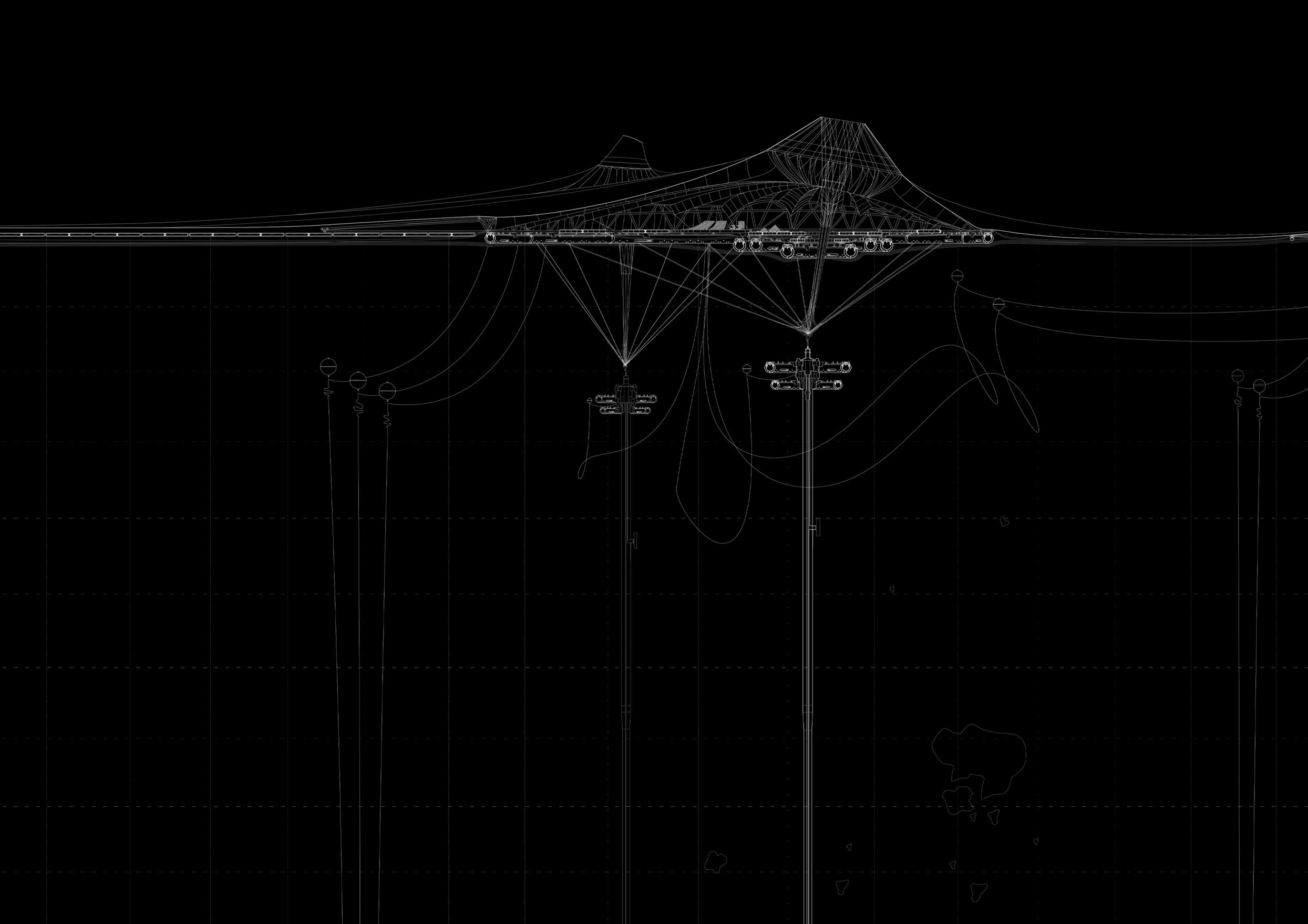
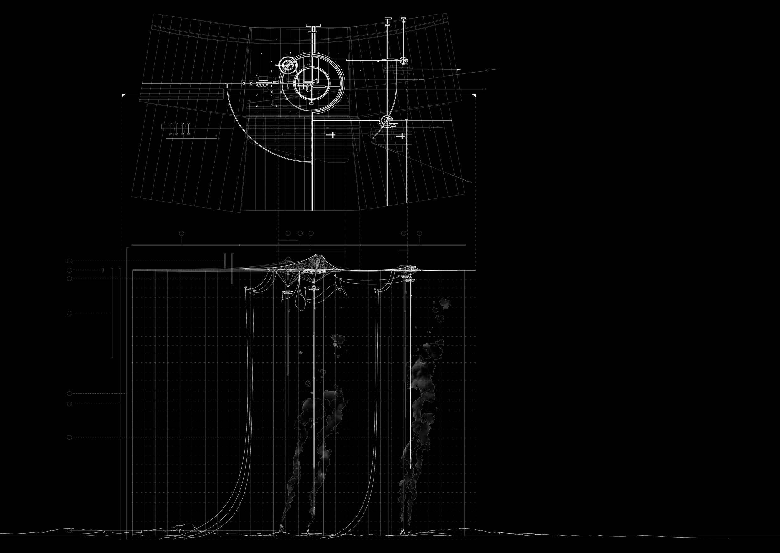
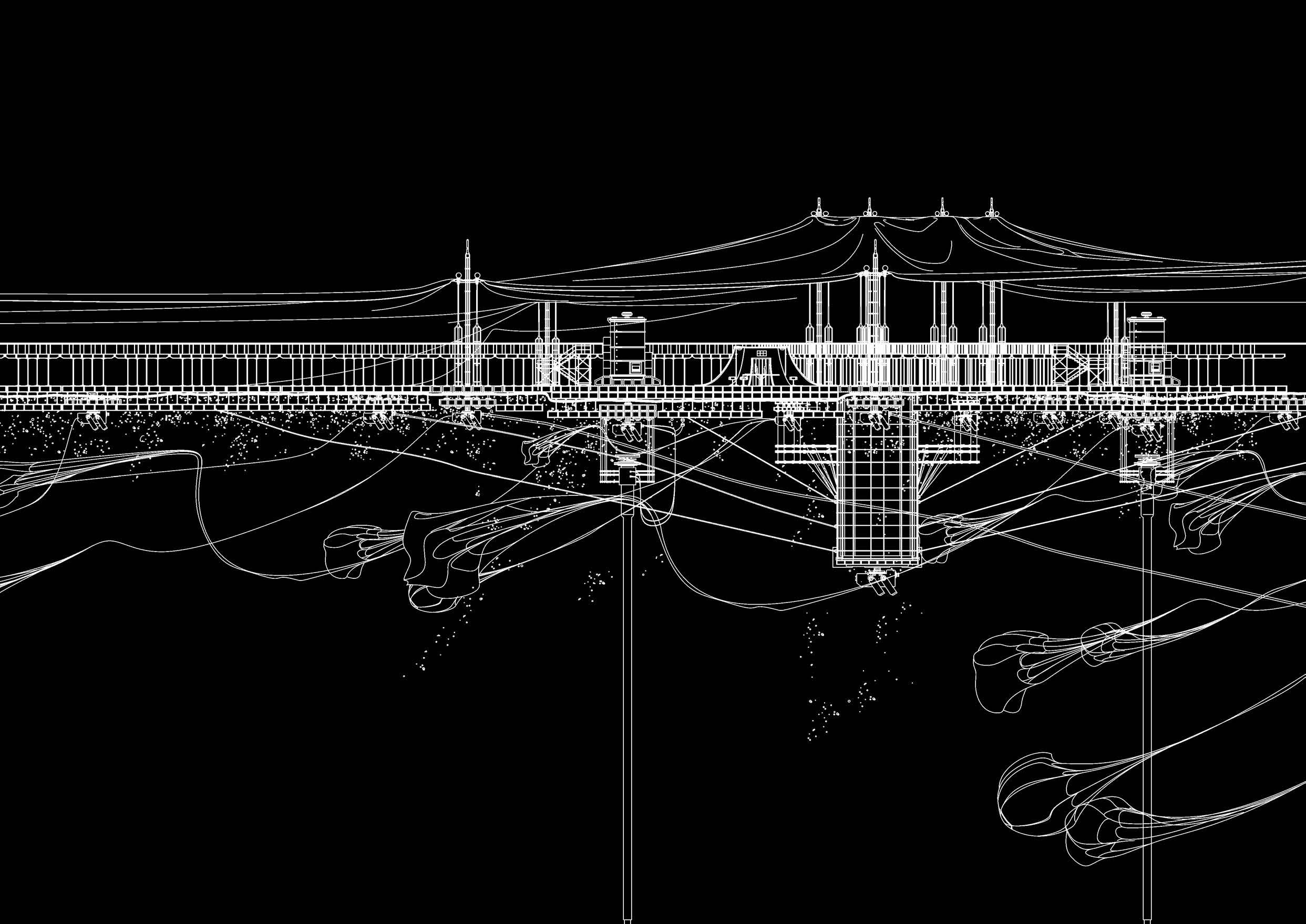
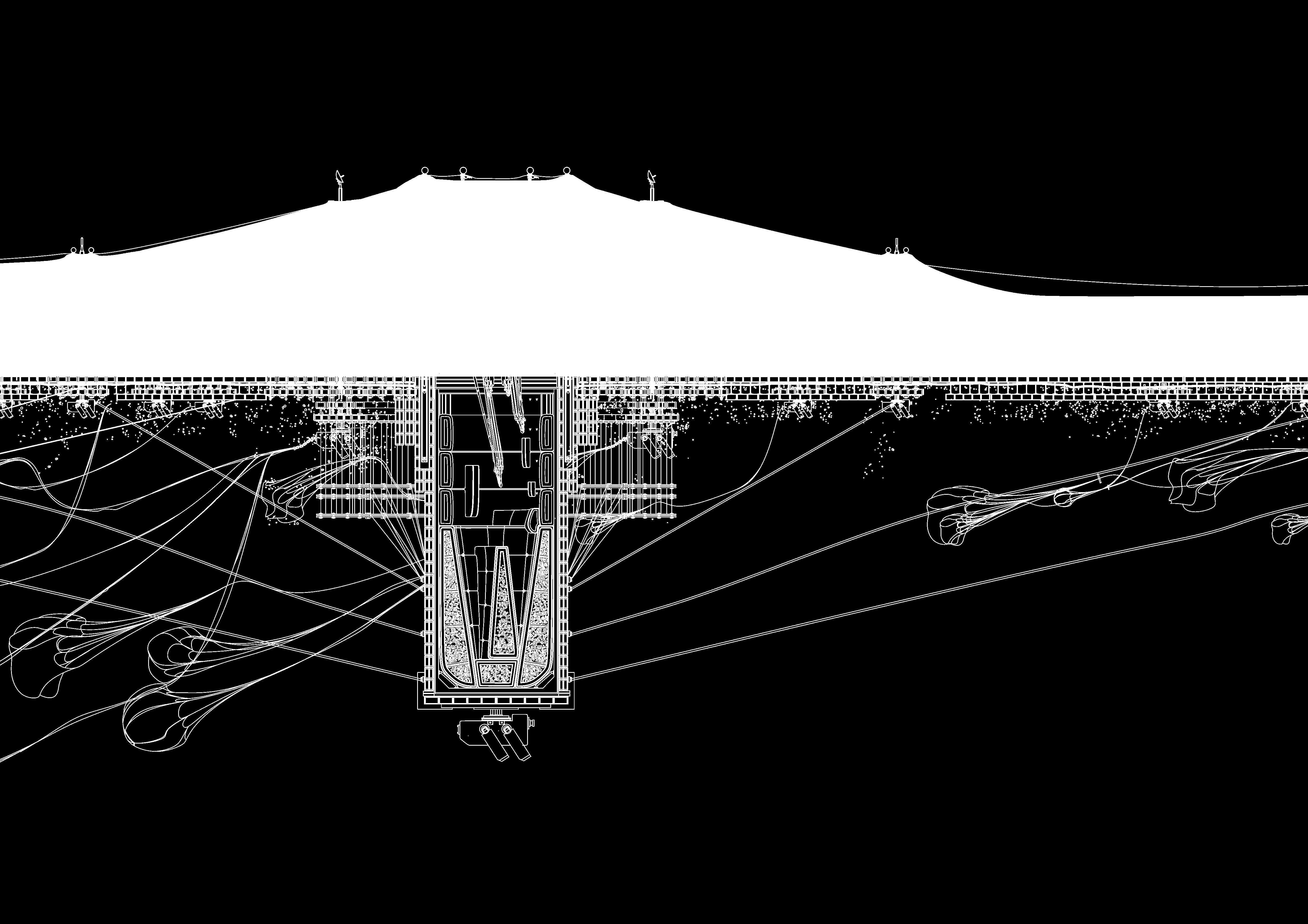
SHEET A-82 | SECTION
The publicly released sections of Mir Outpost provides further insight to the Archive, with labels showing the relative depths of the ocean.

MIR OUTPOST | SECTION
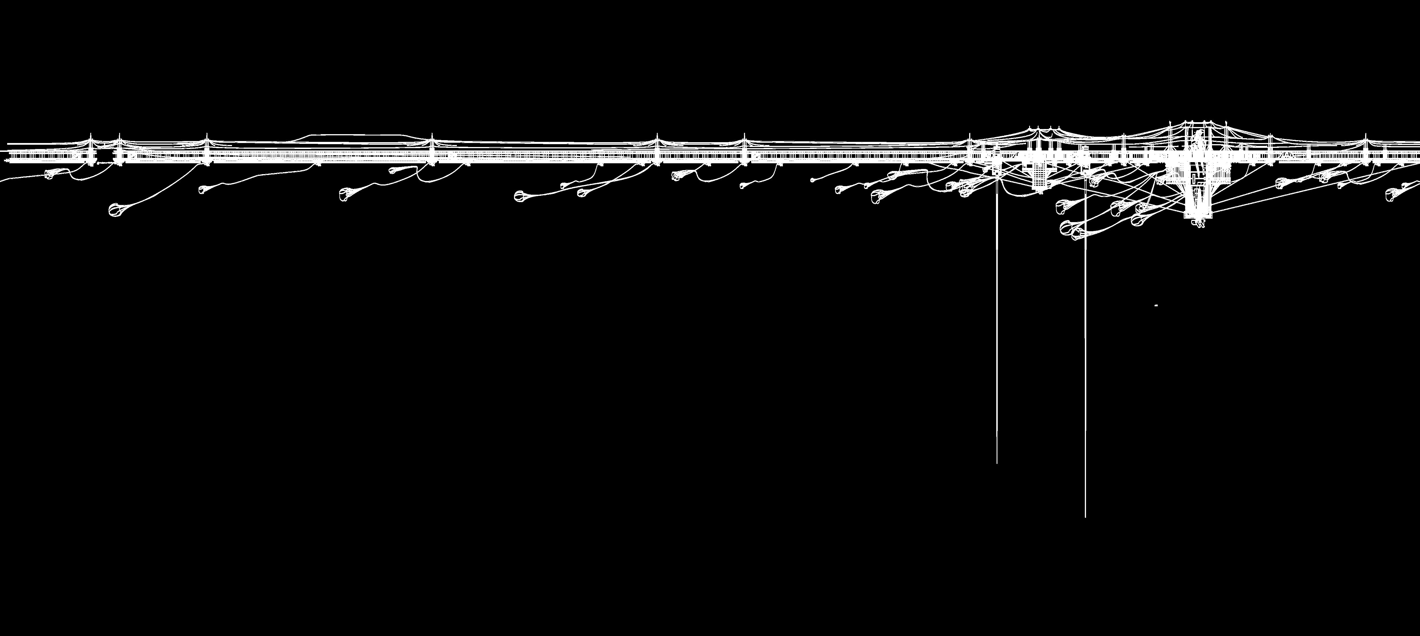
Zooming into the long section, there are 3 vital spaces as highlighted in red.
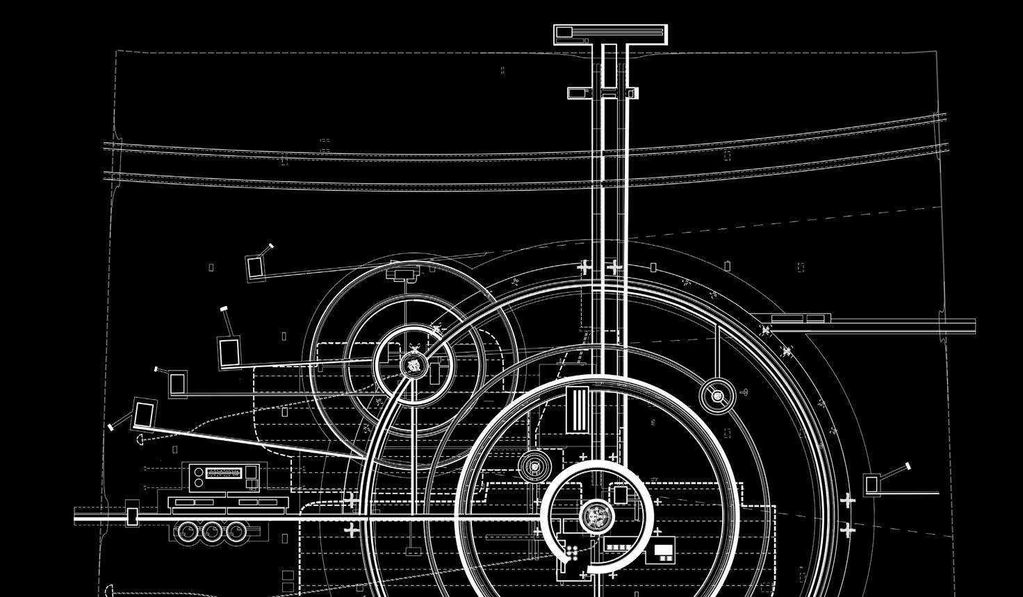
MIR OUTPOST | SECTION DETAIL 1
The first detail provides information on the connection between the sheets. As an underwater pulley system can be seen that likely holds the sheets together while allowing the passage of boats. The columns
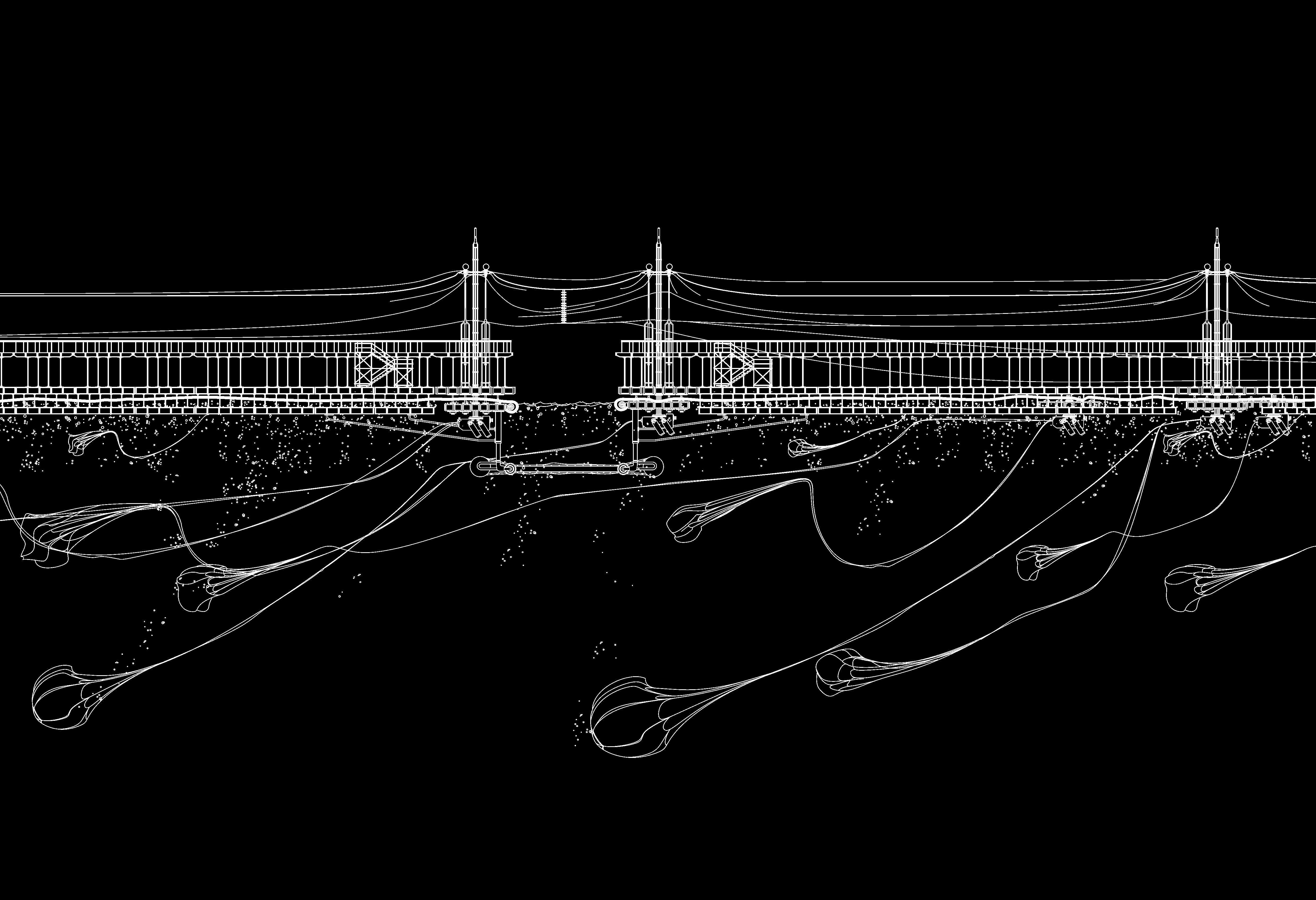
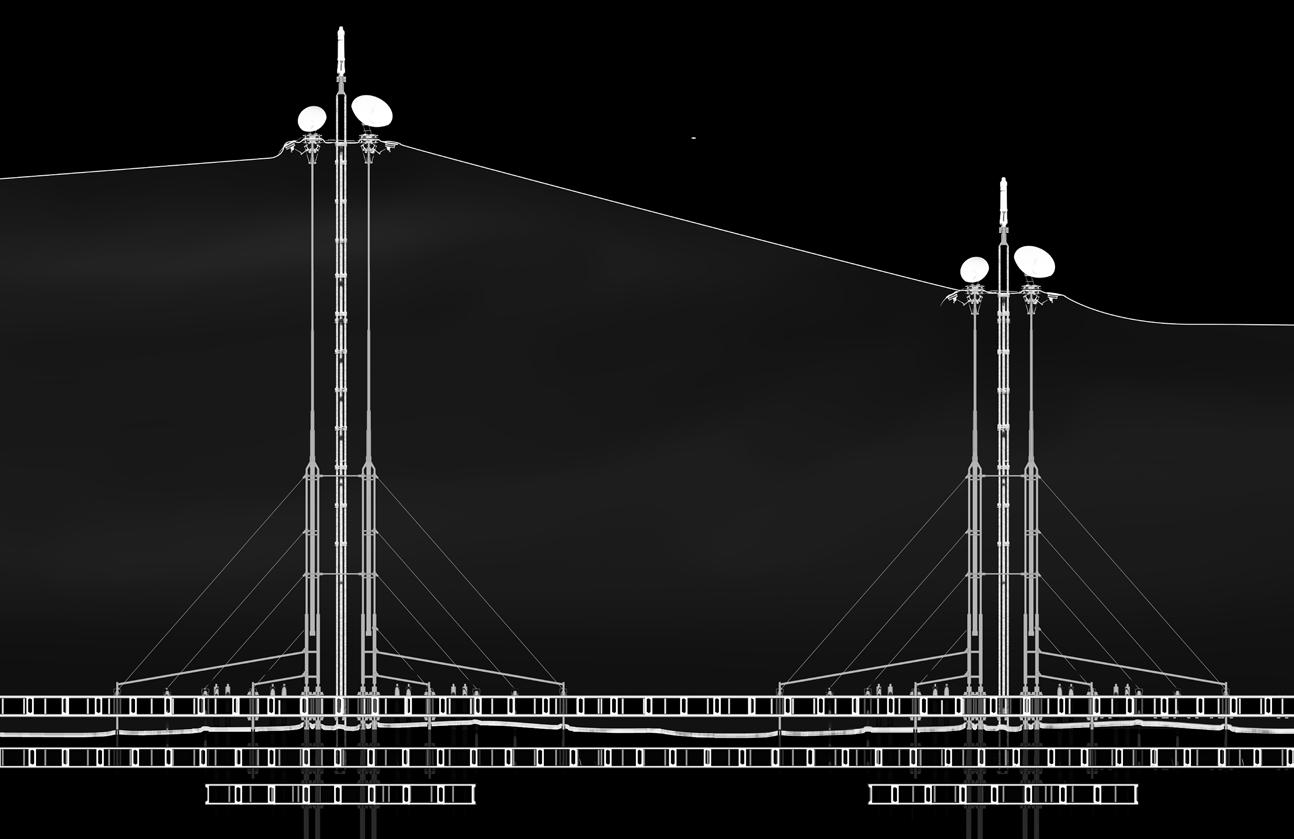
HYDRAULIC COLUMN | HEIGHT ADJUSTMENT
As seen in the section are able to adjust their heights using hydraulics. The changing of their heights allow them to control the tensioning of the fabrics which can help prevent tear and rips.
HYDRUALIC COLUMN | PONTOON DETAIL
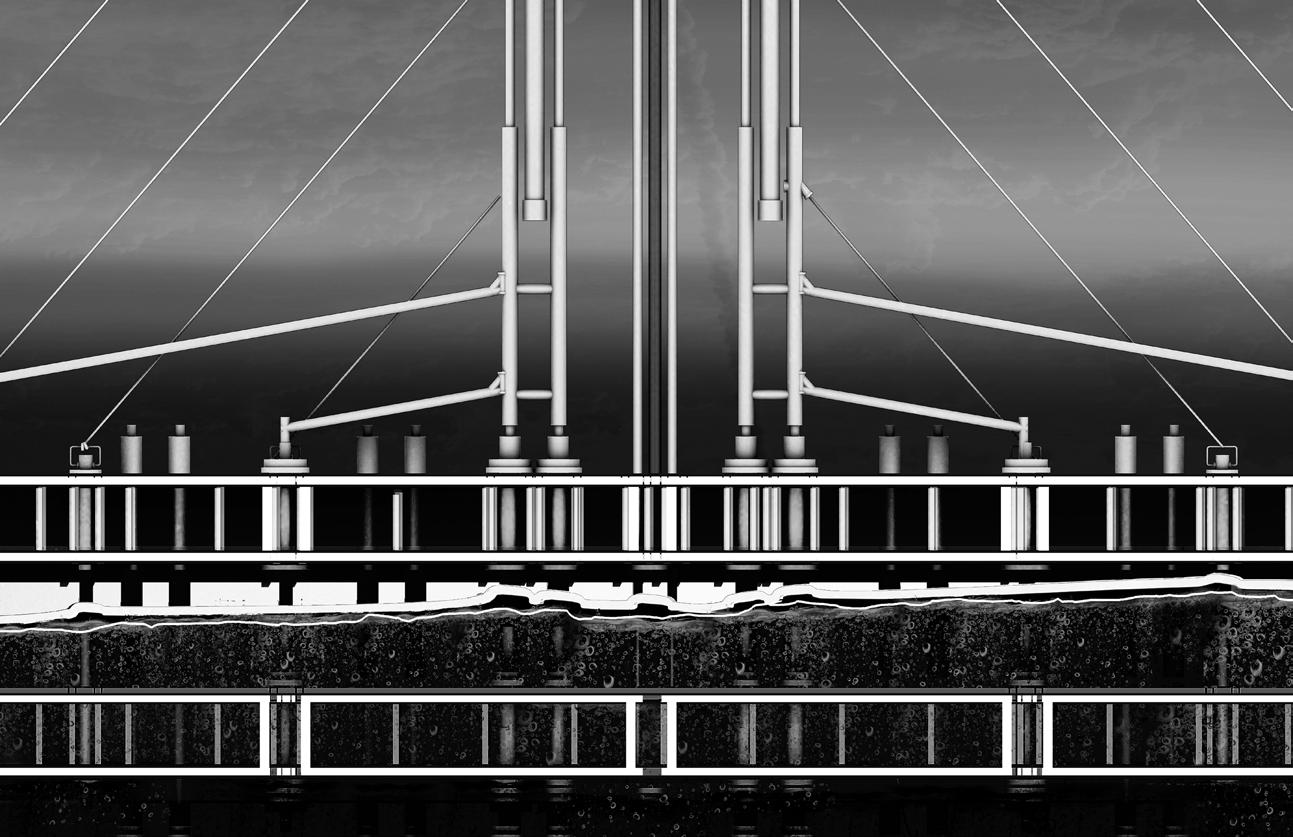 The columns are pinned onto the pontoons and there are two main layers of pontoon foundation, one above and one below water, with a gap of roughly 1 meter in between.
HYDRUALIC COLUMN | FABRIC DETAIL
 At the top of the columns, hydraulic clamps lock the sheets in place, with maintenance lifts installed to its rear and impact absorption joints fitted.
HYDRUALIC COLUMN | FABRIC DETAIL
 Above the fabric are the satellite dishes and signal posts. One dish for communication, and one for detecting meteorites.
MIR OUTPOST | SECTION DETAIL 2
The second sectional detail focuses on the energy facility which includes the OTEC system and energy storage tanks highlighted in red.
ENERGY FACILITY | DETAIL
 The storage tanks as seen in white allows for energy to be safely stored around the entire outpost for emergency use.
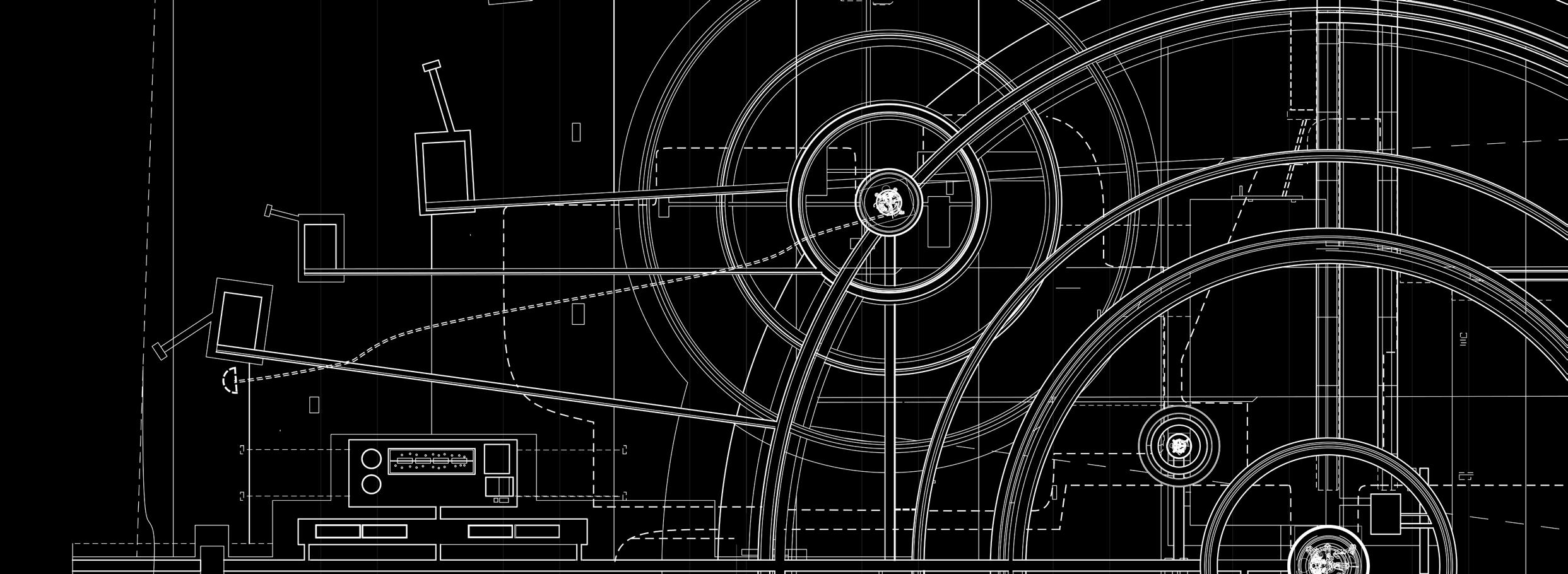
MIR OUTPOST | SECTION DETAIL 3
The third and last sectional blueprint focuses on the main fragment of Mir that is located in the center of the sheet/outpost.
Based on the last section, a colorized version has been digitally generated based on the said materiality.
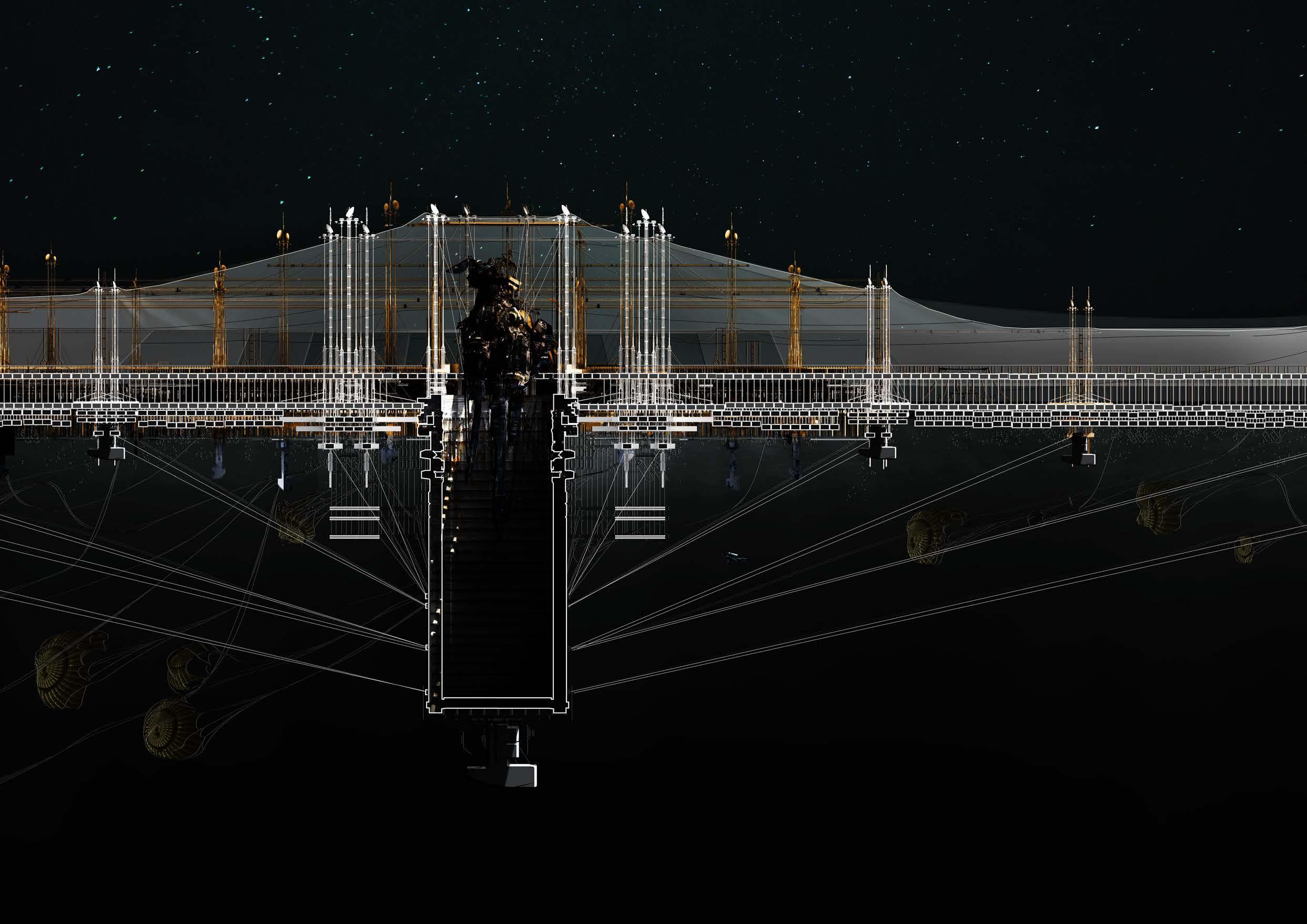

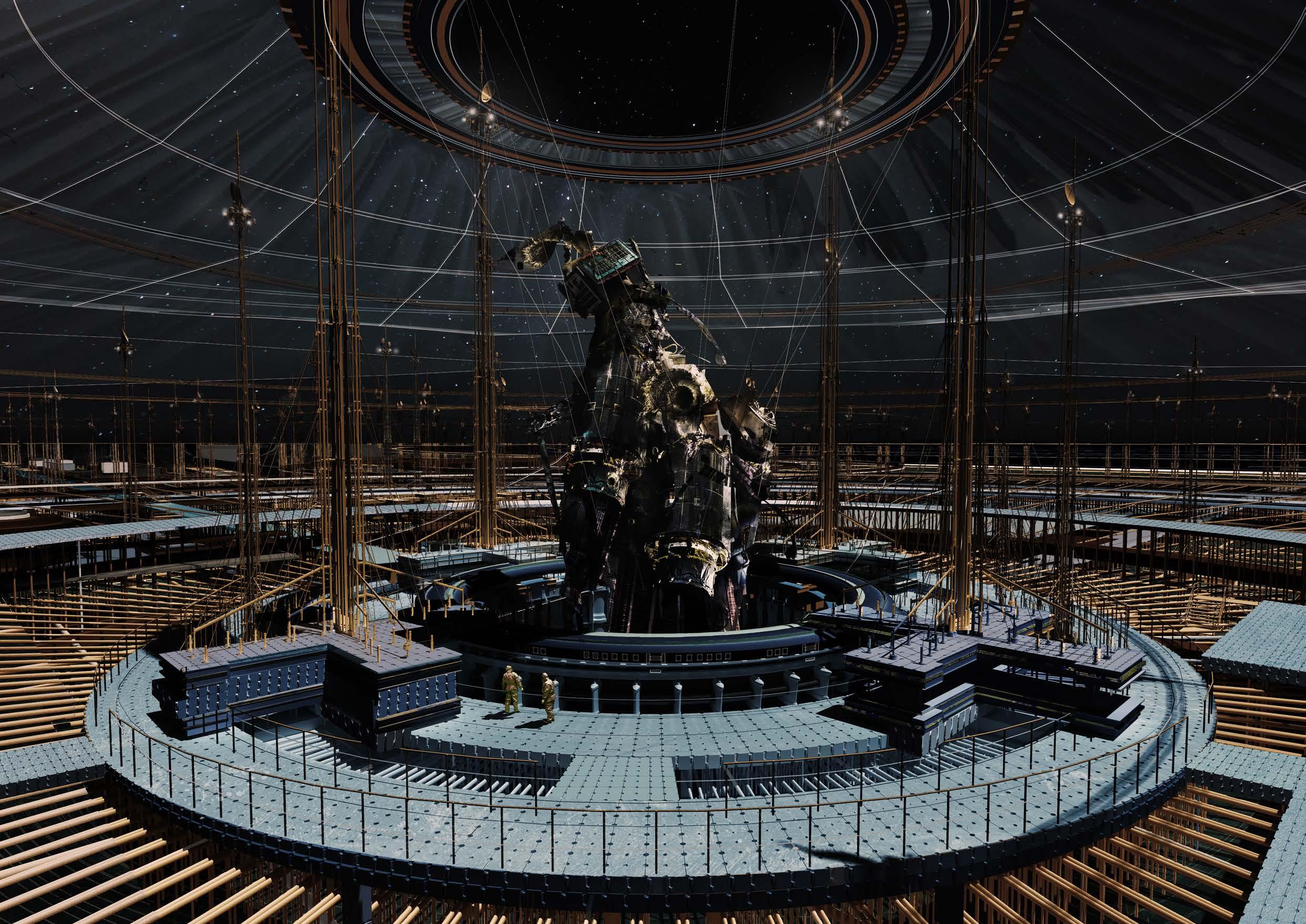
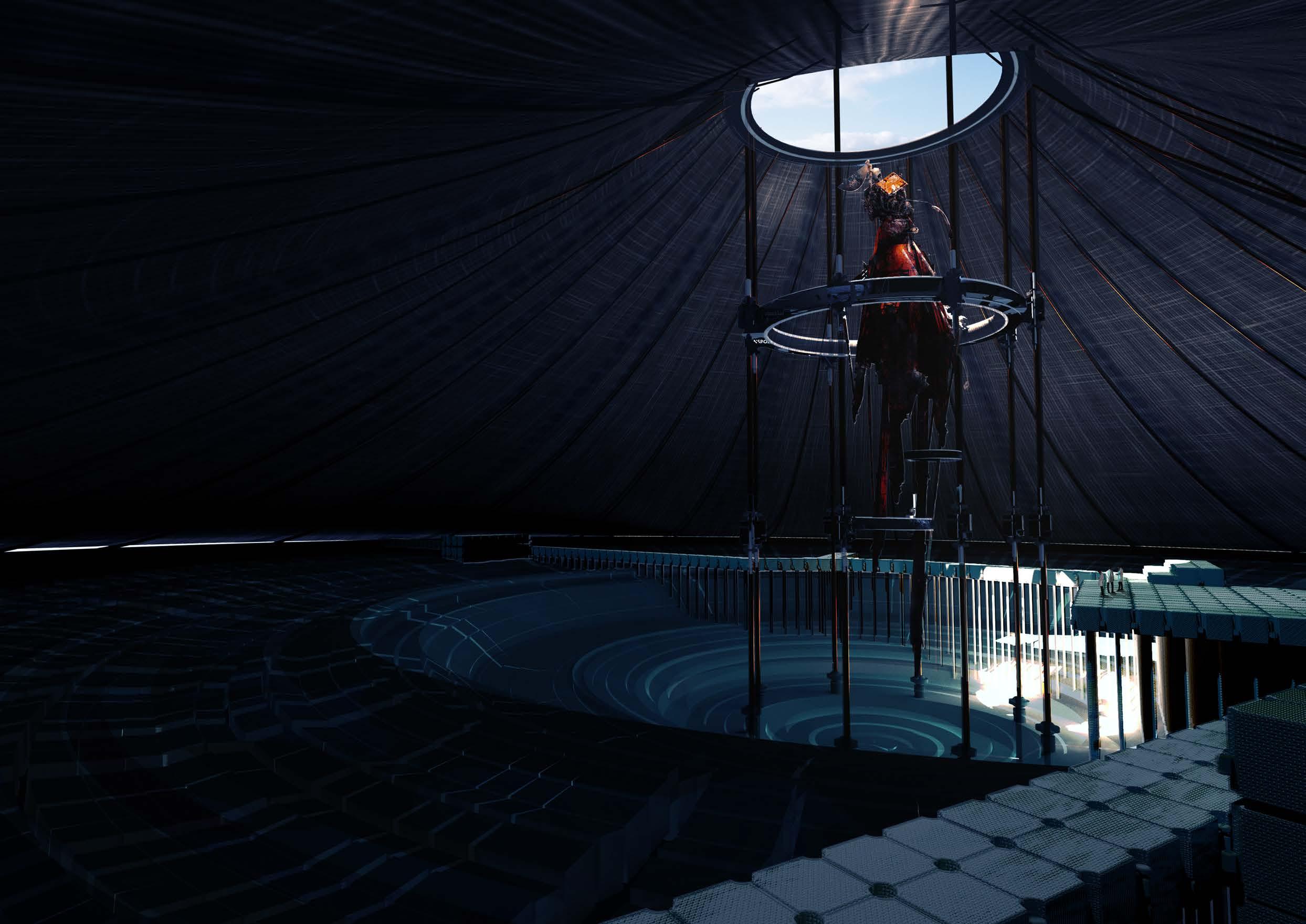
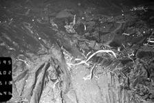
The second of its interiors is taken atop one of the columns. With the main focuses being on the fragment in the center. this is the second largest fragment of Mir, which was still presumably under study in year 2024, as inferred by the tents and researchers on site. Directly behind the fragment is the center of the Mir outpost, which contains the main fragment, as seen just below the horizon.
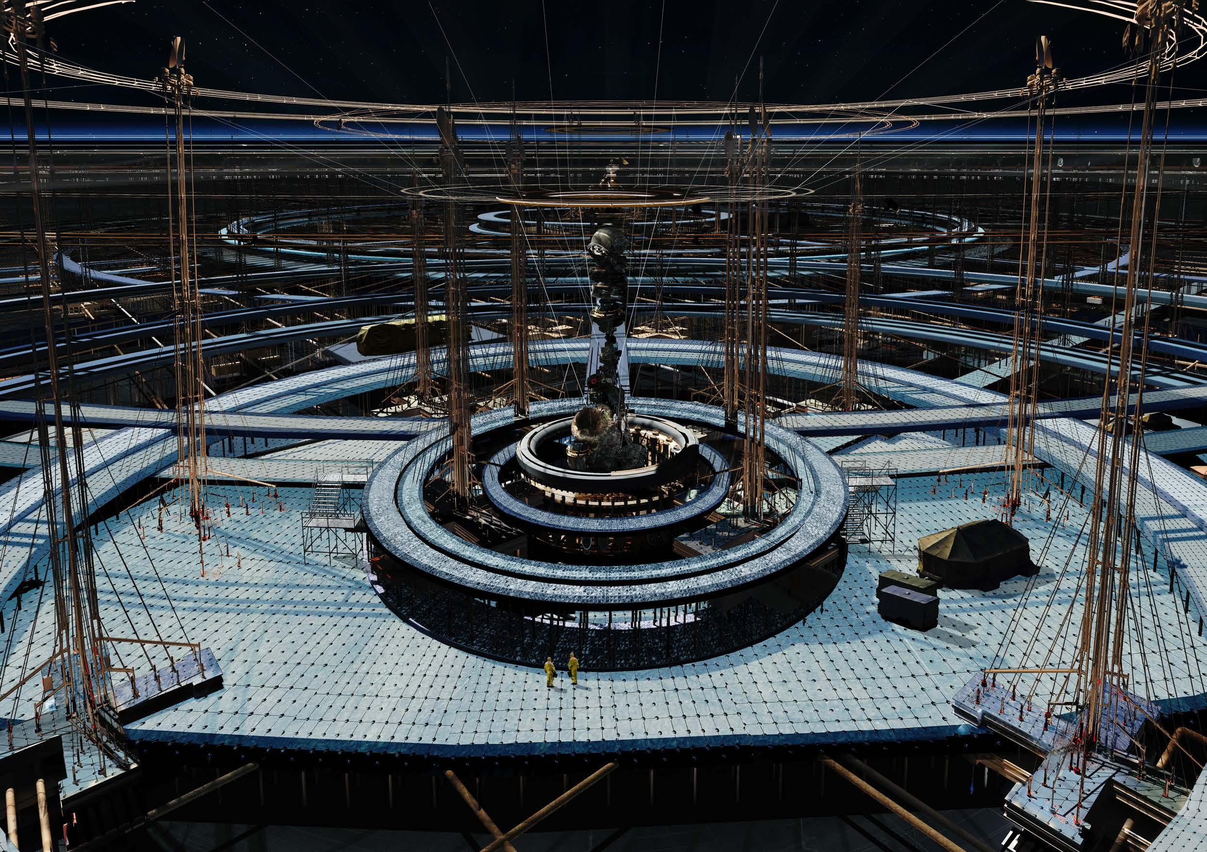
Judging by the photo, the main fragment of Mir looks to be roughly 30m in length and 15 m in width. The facilitation of this fragment is said to be carried out by the stationed crews that conduct hourly check-ins of its temperature, humidity, and other physical condition. Although there have been no public claims of ownership to this fragment, its current estimated 9-digit price tag should make it well worth the effort for the Nemo Space Archive.