
Shutdown
Previous Screen
Product: WHEEL LOADER
Model: 924GZ WHEEL LOADER RTA
Configuration: 924G 924Gz Wheel Loader RTA00001-UP (MACHINE) POWERED BY 3056E Engine
Disassembly and Assembly
IT28G Integrated Toolcarrier and 924G, 924GZ and 928G Wheel Loaders Power Train
Transmission and Torque Converter - Disassemble
SMCS - 3001-015
Disassembly Procedure Table 1
Start By:
a. Remove the transmission. Refer to Disassembly and Assembly, "Transmission and Torque Converter - Remove".
Note: Cleanliness is an important factor. Before you begin the disassembly procedure, the exterior of the components should be thoroughly cleaned. This will help to prevent dirt from entering the internal mechanism.
1. Use Tooling (C) and a suitable lifting device in order to position transmission (2) on Tooling (A) and (B), as shown. The weight of transmission (2) is approximately 500 kg (1100 lb).


2. Remove torque converter (1).
3. Remove bolts (3) and flex plate (4) from torque converter (1).
 Illustration 1
g00653680
Illustration 2
g00671890
Illustration 3
g01005185
Illustration 1
g00653680
Illustration 2
g00671890
Illustration 3
g01005185
4. Disconnect harness assembly (4A) from the valve assembly.
Note: Mark each valve group for installation purposes.
5. Remove bolts (4B) and remove valve assembly (4C).
6. Repeat Step 5 for the remaining valve assemblies.
7. Remove bolts (4D) from the relief valve. Remove bolts (4E) and remove the manifold assembly.

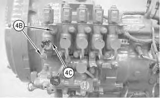 Illustration 4 g01005186
Illustration 5 g01005187
Illustration 4 g01005186
Illustration 5 g01005187
8. Remove bolts (5) and plate (6).


9. Remove lip seal (7) and seal (8).
10. Remove bolts (9).
Illustration 6 g00653775 Illustration 7 g00653801 Illustration 8 g00653806

 Illustration 9
g00653808
11. Remove gear assembly (10).
12. Remove O-ring seals (11).
Illustration 10
g00653825
13. Remove bolts (12) and gear (13).
Illustration 11
g00653848
14. Remove bearing cups (14).
Illustration 9
g00653808
11. Remove gear assembly (10).
12. Remove O-ring seals (11).
Illustration 10
g00653825
13. Remove bolts (12) and gear (13).
Illustration 11
g00653848
14. Remove bearing cups (14).
15. Using Tooling (D) to remove the forward low and the forward high clutch group (15). The weight of the forward low and the forward high clutch group (15) is approximately 27 kg (60 lb).


Note: When the clutch groups are disassembled, remove shaft plugs (16) in order to clean the oil passages. Use a punch to drive the plug into the shaft . Drill the remainder of the aluminum plug out of the bore. Be careful not to drill any portion of the walls of the bore. Use shop air or a cleaning solution in order to clean the shafts.
 Illustration 12
g00653858
Illustration 13
g00653893
16. Remove retaining ring (17) and washer (18).
Illustration 12
g00653858
Illustration 13
g00653893
16. Remove retaining ring (17) and washer (18).
Illustration 14 g00653932
17. Remove retaining ring (19).
18. Use a suitable press in order to remove gear (20).


Illustration 15 g00890607
19. Remove retaining ring (22). Remove hub (21). Remove plates and discs (23).
Note: Take note of the number and order of plates and discs for assembly purposes.
Illustration 16 g00653959
20. Remove washer (24).
Note: The retainer may stick to the inside of hub (21) when the hub is removed.
21. Remove retaining ring (26). Press bearing (25) from hub (22).
Personal injury can result from being struck by parts propelled by a released spring force.
Make sure to wear all necessary protective equipment.
Follow the recommended procedure and use all recommended tooling to release the spring force.
22. Put the forward low clutch group in a suitable press. Use Tooling (H) in order to compress the spring. Remove retaining ring (27).

 Illustration 17
g00890608
Illustration 18
g00654018
Illustration 17
g00890608
Illustration 18
g00654018
Illustration 19 g00654029
23. Remove retainer (28) and spring (29).


Illustration 20 g00890609
24. Blow shop air 276 kPa to 414 kPa (40 psi to 60 psi) into lube passage (31) in order to remove piston (32).

25. Remove seals (30).
Illustration 21 g00654063
26. Remove O-ring seals (33).
Illustration 22
g00654078
27. Disassemble the forward high clutch group by removing retaining ring (34). Remove washer (35).


Illustration 23
28. Remove ring (36). Remove gear (37).
g00654253
Illustration 24
29. Remove hub (38).
g00654261
g00654263
30. Remove retaining ring (39). Use a suitable press in order to remove bearing (40).


g00654274
31. Remove washer (41). Remove retaining ring (42). Remove the plate and discs (43).
Note: Take note of the number and order of plates and discs for assembly purposes.
Illustration 25 Illustration 26 Illustration 27 g00654276Personal injury can result from being struck by parts propelled by a released spring force.
Make sure to wear all necessary protective equipment.
Follow the recommended procedure and use all recommended tooling to release the spring force.
32. Put the forward high clutch group in a suitable press. Use Tooling (H) in order to remove retaining ring (44).


33. Remove retainer (45) and spring (46).
34. Blow shop air 276 kPa to 414 kPa (40 psi to 60 psi) into lube passage (48) in order to remove piston (47).
Illustration 28 g00654280 Illustration 29 g00654282Illustration 30
35. Remove O-ring seals (49) and (50).

g00654292
Illustration 31
g00654301
36. Use Tooling (D) in order to remove reverse second gear clutch group (51). The weight of reverse second gear clutch group (51) is approximately 32 kg (70 lb).
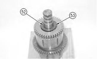

Illustration 32
g00654339
37. Remove retaining ring (52) and washer (53).
Illustration 33
38. Remove retaining ring (54) and gear (55).


g00654328
Illustration 34
39. Remove hub assembly (56).

g00654347
Illustration 35
40. Remove washer (58).
g00890610
41. Remove retaining ring (57). Remove plates and discs (59).
Note: Take note of the number and order of the plates and discs for assembly purposes.
Illustration 36
g00890611
42. Remove retaining ring (60). Use a suitable press in order to remove bearing (61).


Illustration 37
g00654360
Personal injury can result from being struck by parts propelled by a released spring force.
Make sure to wear all necessary protective equipment.
Follow the recommended procedure and use all recommended tooling to release the spring force.
43. Put the reverse clutch group in a suitable press. Use Tooling (H) in order to remove retaining ring (62).
44. Remove retainer (63) and spring (64).


Illustration 40
45. Blow shop air 276 kPa to 414 kPa (40 psi to 60 psi) into lube passage (66) in order to remove piston (65).
46. Remove seals (67).
Illustration 38 g00654364 Illustration 39 g00654372 g00654378Illustration 41 g00654403
47. Remove O-ring seals (68) and (69).
Illustration 42 g00890612
48. Install a suitable puller under gear (72). Pull gear (72), spacer (70), and bearing cone (71).


49. Remove spacer (73). Remove washer (74) and (75).
Note: Use Steps 38 through 47 for the remaining disassembly of the second gear clutch group. In Step 43, use Tooling (E) instead of Tooling (H).
50. Use Tooling (D) in order to remove first third gear clutch group (76). The weight of first third gear clutch group (76) is approximately 50 kg (110 lb).


Illustration 44
g00654497
51. Remove retaining ring (77) and washer (78).
Illustration 45
52. Remove retaining ring (79) and gear (80).
g00654507
Illustration 46
53. Remove hub assembly (81).
g00654512
Illustration 47
g00890613
54. Remove retaining ring (82). Use a suitable press in order to remove bearing (83).

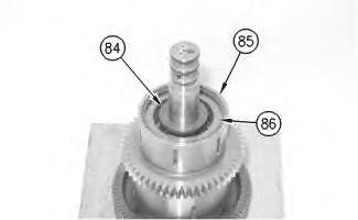

Illustration 48
55. Remove washer (84).
g00654519
56. Remove retaining ring (85). Remove plates and discs (86).
Note: Take note of the number and order of the plates and discs for assembly purposes.
Illustration 49 g00654525
Personal injury can result from being struck by parts propelled by a released spring force.
Make sure to wear all necessary protective equipment.
Follow the recommended procedure and use all recommended tooling to release the spring force.
57. Put the third gear clutch group in a suitable press. Use Tooling (H) in order to remove ring (87).

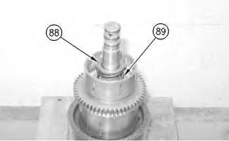
Illustration 50
58. Remove retainer (88) and spring (89).
g00654534
Illustration 51
g00890615
59. Blow shop air 276 kPa to 414 kPa (40 psi to 60 psi) into lube passage (91) in order to remove piston (90).
60. Remove seals (92).
Illustration 52 g00654638
61. Remove O-ring seals (93) and (94).
Illustration 53 g00890617
62. Disassemble the first gear clutch by installing Tooling (G) through the holes in gear (95). Pull gear (95), washer (96), and bearing (97) together.


Illustration 54
g00654719
63. Remove washer (98). Remove retaining ring (99) and gear (100).

Illustration 55
64. Remove hub assembly (101).


g00654724
Illustration 56
g00890619
65. Remove washers (102) and (104). Remove retaining ring (103). Remove plates and discs (105).

Note: Take note of the number and order of the plates and discs for assembly purposes.
Illustration 57
66. Remove ring (106).
g00654818
Make sure to wear all necessary protective equipment.
Follow the recommended procedure and use all recommended tooling to release the spring force.

 Illustration 58 g00654824
67. Remove bearing assembly (107).
Illustration 59 g00654833
Personal injury can result from being struck by parts propelled by a released spring force.
68. Put the clutch group in a suitable press. Use Tooling (H) in order to remove retaining ring (108).
Illustration 58 g00654824
67. Remove bearing assembly (107).
Illustration 59 g00654833
Personal injury can result from being struck by parts propelled by a released spring force.
68. Put the clutch group in a suitable press. Use Tooling (H) in order to remove retaining ring (108).
Illustration 60 g00654837
69. Remove the retainer and seal assembly (109).
Illustration 61 g00654842
70. Remove spring (110).


Illustration 62 g00654966
71. Blow shop air 276 kPa to 414 kPa (40 psi to 60 psi) into the lube passage in order to remove piston (111).
Illustration 63
72. Remove seals (112), (113), and (114).
Illustration 64
73. Remove input shaft assembly (115).
Illustration 65
74. Remove carrier (117) and seal (116). Remove bearing cone (121) and gear (120).


75. Remove bearing cone (118) and gear (119).
 g00654969
g00655016
g00890621
g00654969
g00655016
g00890621
Illustration 66
76. Remove bearing (122) and bearing cups (123).


Illustration 67
77. Remove bolt (124), washer (125), and yoke (126).

Illustration 68 g00685060
78. Remove the bolt and washer (127).
Thank you very much for your reading. Please Click Here. Then Get COMPLETE MANUAL.NOWAITING

NOTE:
If there is no response to click on the link above, please download the PDF document first and then clickonit.
Illustration 69 g00890622
79. Remove seal (128). Remove yoke (129) and brake drum (130) together.

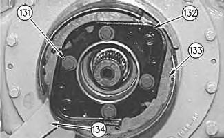

Illustration 70 g00890758
80. Remove bolts (131). Remove plate (132).
81. Remove parking brake assembly (133) and lever (134).
Illustration 71 g00655180
82. Remove bolts (135).
Illustration 72 g00655189
83. Install bolts (136). Tighten bolts (136) in order to remove cage (137). Remove the shims that are under the cover.


Illustration 73 g01005236
84. Remove seal (138). Remove bearing cup (139) and lip seal (140).
Illustration 74 g01005238
85. Remove the output shaft and gear (141).
86. Remove bolts (142) and shield assembly (144).


87. Remove bearing cup (143) and lip seal (145).
 Illustration 75