
Document Title:

Profile:
Description
The EC15/EC20B is powered by a water-cooled 3-cylinder four-stroke inline diesel engine with water cooling.
Document Title: Function Group: Information Type: Date: Engine trouble shooting 200 Service Information 2014/6/22
Profile:
Engine trouble shooting
Engine faults must be detected and rectified as quickly as possible in order to avoid more expensive repairs. The following table summarizes the most important faults and their rectification.
Problem/fault Possible cause of fault
Fault remedy Starter switch defective
Tighten connections. Replace the switch. Engine does not start Starter power too low
Air in fuel system
Air filter dirty
Wrong oil viscosity
Engine too cold
Injection valves defective
Incorrect injection timing
Compression pressure too low
If the starter is OK, check condition of battery and electric connections.
Bleed the system.
Replace the air filter.
Check viscosity and fill in correct oil.
Check the function of the preheater plug.
Check and adjust the injection valves
Replace defective valves.
Adjust the injection timing. Check the valve clearance.
Check condition of cylinder head gasket, valves and piston rings.
Fill in fuel. Engine shuts down automatically
Fuel tank empty
Air in fuel system
Fuel filter dirty
Fuel pump defective
Exhaust system clogged
Bleed the fuel system.
Clean or replace the fuel filter.
Check connection of fuel pump or replace fuel pump.
Clear or replace the exhaust system.
Replace the pump. Erratic running of engine
Engine overheating
Fuel pump defective
Fuel filter dirty
Air filter dirty
Injection valves defective
Cooling system elements defective
Clean or replace the fuel filter.
Bleed the fuel system.
Clean the air filter. Check the intake air.
Check and adjust the injection valves
Replace defective valves.
Check elements (water pump, radiator, thermostat, cylinder head gasket, coolant hoses).
Check presence, tension and cleanliness of V-belt. Lubrication system elements defective Check elements (oil filter, oil pump, suction filter) and replace defective parts.
Fan not running
Incorrect injection timing
Oil level too low
Governor incorrectly adjusted
Coolant level not correct
Adjust the injection timing. Check the valve clearance.
Fill in oil. Check whether the oil in the engine meets the operating conditions.
Adjust the governor.
Correct the coolant level. Check whether the coolant meets the operating conditions.
Clean or replace the air filter. Engine develops black smoke
Air cleaner soiled
Poor fuel quality
Check quality of fuel and suitability for climatic
Irregular idle speed
Unusual engine noise
conditions.
Valve clearance and injection timing not correct Adjust valve clearance and injection timing.
Compression pressure not O.K. Check condition of cylinder head gasket, valves and piston rings.
Injection pressure not O.K. Check and adjust the injection valves
Injection pump defective Check injection pump, replace if necessary.
Engine control cable incorrectly adjusted Adjust the control cable.
Poor engine oil quality
Poor fuel quality
Fill in oil as required for the operating conditions.
Check quality of fuel and suitability for climatic conditions.
Valve clearance and injection timing not correct Adjust valve clearance and injection timing.
Opening pressure of injection valves not correct Check opening pressure and injection valves.
Compression pressure not O.K. Check condition of cylinder head gasket, valves and piston rings.
Injection pump defective Check injection pump, replace if necessary.
Poor fuel quality
Check quality of fuel and suitability for climatic conditions.
Air cleaner soiled Clean or replace the air filter.
Incorrect injection timing Adjust the injection timing.
Engine shut-down solenoid not O.K. Check the engine shut-down solenoid.
Injection pressure not O.K. Adjust the injection valves.
Compression pressure not O.K. Check condition of cylinder head gasket, valves and piston rings.
Injection pump defective Replace the injection pump.
Oil level and oil quality not correct Check oil level and oil quality and fill in specified oil. Oil pressure too low
Oil pressure switch defective Check and replace the oil pressure switch.
Tighten the V-belt and replace a defective V-belt. Battery charge condition too low
Engine cannot be shut down
Fan V-belt too loose
Generator defective Check and replace the generator.
Battery defective Replace the battery.
Wiring not O.K.
Check correct connection of cables.
Regulator defective Check regulator, replace if necessary.
Starter switch defective Tighten connections. Replace the switch.
Engine shut-down solenoid not O.K. Check the engine solenoid, replace if necessary.
Document Title: Function Group: Information Type: Date: Installing the engine 200 Service Information 2014/6/22
Profile:
Installing the engine
Op nbr 2101
Lifting sling 1 m Shackle 3/8""
1. Attach the lifting tackle to the engine. Weight approx. 125 kg.
2. Place the engine into the engine carrier.
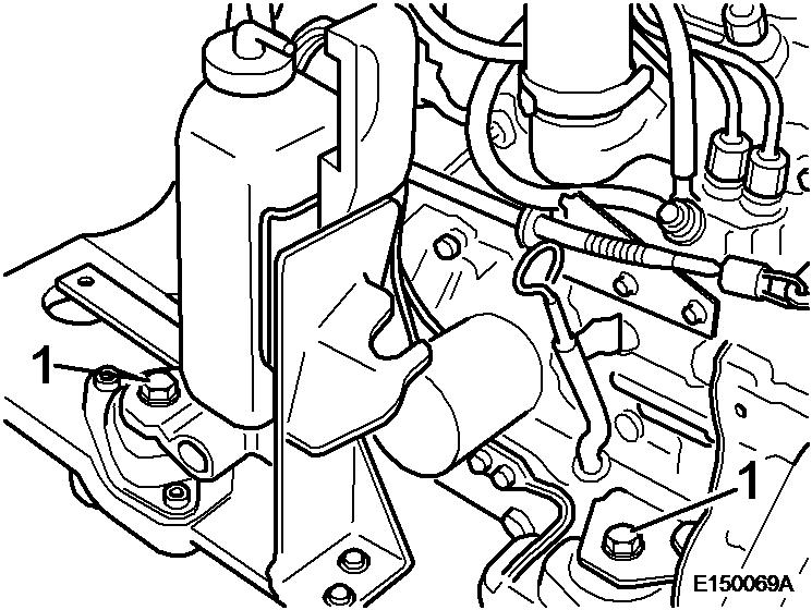
3. Cover the threads of screws (1) with Loctite, turn them into the rear engine suspension and tighten with 105 Nm.
4. Cover the threads of screws (5) with Loctite, turn them into the front engine suspension and tighten with 105 Nm.
5. Assemble the exhaust system with a new seal to the exhaust manifold.
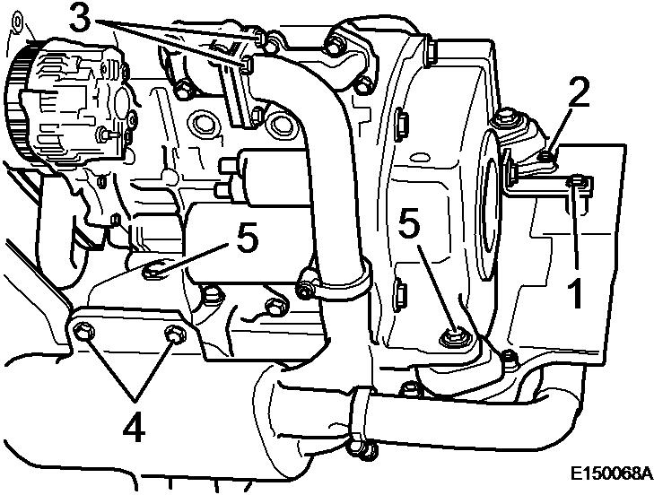
6. Turn in screws (1 and 2) and tighten with 30 ± 5 Nm.
7. Fasten the exhaust bracket to the engine carrier and tighten the screws (4 and arrow) with 60 ± 10 Nm.
8. Turn in screw (1) on both tie rods and tighten with 30 ± 5 Nm.
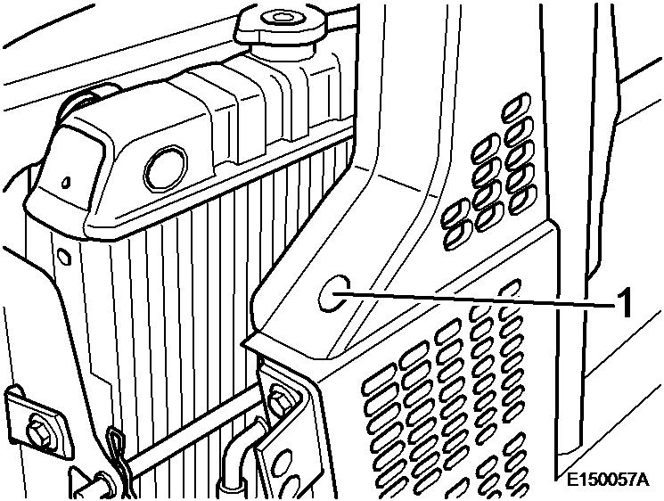
9. Attach the radiator grid, turn in screws (1) and tighten with 30 ± 5 Nm.
10. Assemble top and bottom coolant hose with new hose clamps.
11. Close the drain screw and fill in coolant. Filling capacity: approx. 5 l
12. Insert the engine with radiator and engine carrier and connect the following components:
Generator Starter
13. Push the engine forward and lower it.
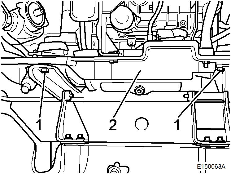
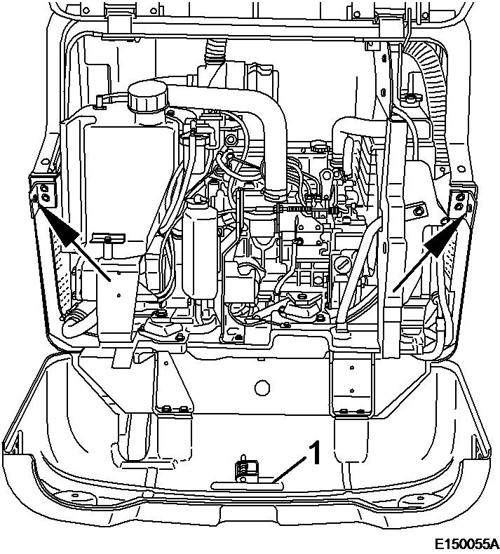
14. Turn the fastening screws (1) into the engine carrier (2) and tighten with 105 Nm.
15. Remove the lifting tackle to the engine.
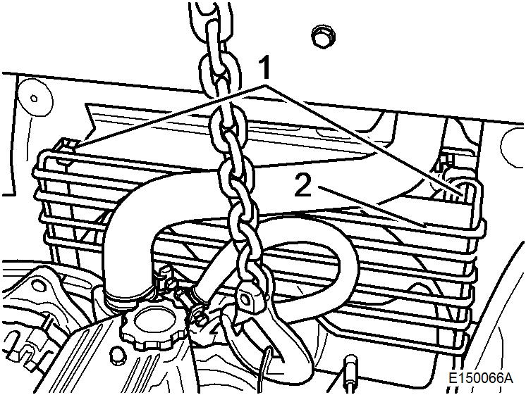 Figure 3
Figure 4
Figure 3
Figure 4
16. Install oil cooler (4) and tighten screw (1) with 12 ± 2 Nm.
17. Insert rod (3) and secure with clamp (2).
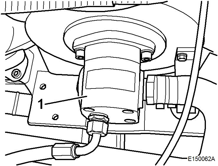
18. Install hydraulic pump (1), cover the screws with Loctite, turn them in and tighten with 105 Nm.
19. Assemble fuel tank, filter and air filter and tighten the screws (3) with 30 ± 5 Nm.
20. Connect fuel line (2).
21. Fasten throttle control (1) on injection pump and adjust throttle cable.
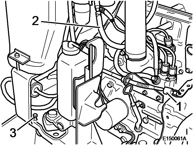 Figure 6
Figure 7
Figure 8
Figure 6
Figure 7
Figure 8
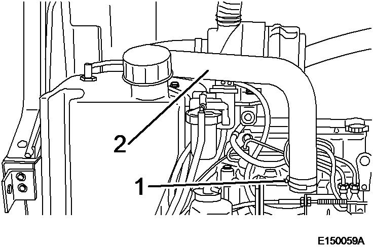
22. Connect the breather line (1) to the hydraulic oil tank.

23. Install the engine wiring loom and connect the following components:
Air filter contamination indicator
Fuel sensor
Glow plug
Shut-off solenoid
Plug for hand lamp
Temperature switch
Ground strap on engine and engine carrier
Fasten the cables with cable straps.
24.
Figure 928. Bleed the fuel system.
29. Connect the ground cable to the battery.
30. Lift the counterweight up and fasten with the screws.
31. Check engine oil level, top up if necessary
32. Start the engine and make sure that there are no leaks.
Operator side
Oil
Coolant

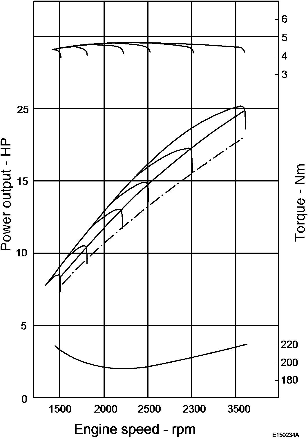
Performance characteristics (measuring values for
Document Title: Function Group: Information Type: Date:
Removing the engine 200 Service Information 2014/6/22
Profile:
Removing the engine
Op nbr 2101
Lifting sling 1 m
Shackle 3/8""
WARNING
Disconnect and connect the battery only with the ignition switched off. Disconnect the minus pole (green fastening) first. During assembly connect the plus pole (red cable) first.
1. Disconnect the ground cable from the battery.
2. Unscrew both screws (arrows) on both sides of the counterweight.

3. Pull safety lever (1) and move the counterweight to bottom position.

8.
9.
Air filter contamination indicator
Fuel sensor
Glow plug
Engine shut-down solenoid
Plug for hand lamp
Temperature switch
Ground strap on engine and engine carrier
10.
4. Unscrew the front socket head cap screws (1) for the hood (2).
Figure 3
5. Loosen hose clamp (1) and place the stop hose (2) to the side.
Figure 4
6. Unscrew both rear socket head cap screws (1) and take off hood with engine hood.
Figure 5
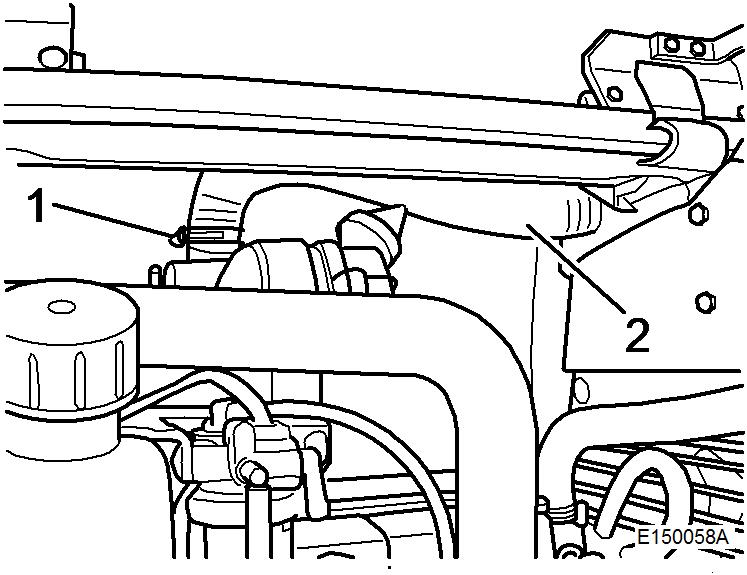
7. Loosen hose clamp (1) and pull air intake hose (2) off the air intake pipe.
Close openings on the engine with adhesive tape.
11. Remove the breather line (1) from the hydraulic oil tank.
12. Unhook throttle cable (1) from the injection pump.
13. Disconnect fuel supply line (2).
14. Unscrew all screws (3) from the fuel tank.
15. Remove fuel tank, filter and air filter as one unit.
16. Disassemble hydraulic pump (1) from engine, lay to the side and fasten it safely.
Figure 6
Figure 7
Figure 8
18. Attach lifting tackle (1) to the engine.
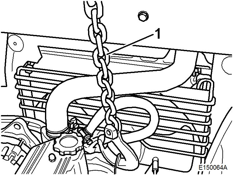
19. Lift the engine up and pull it out towards the rear.
20. Disconnect all necessary electrical cables from the following components:
21. Unscrew screw (1).
22. Unhook calmp (2) and push out rod (3).
23. Lay oil cooler (4) to the side and fasten it.
24. Lift out engine with radiator and engine carrier.
Figure 9 17. Unscrew fastening screws (1) for engine carrier (2). Figure 10WARNING
When opening the lid of the compensation tank (radiator cap) there is a risk of scalding because of the overpressure in the cooling system. Catch running out coolant and dispose of environmentally.
25. Unscrew the drain plug, open the radiator cap and drain of all coolant. Filling quantity approx. 5 litres.
26. Disconnect the water hose from the compensation container on the radiator.
27. Remove top and bottom coolant hose
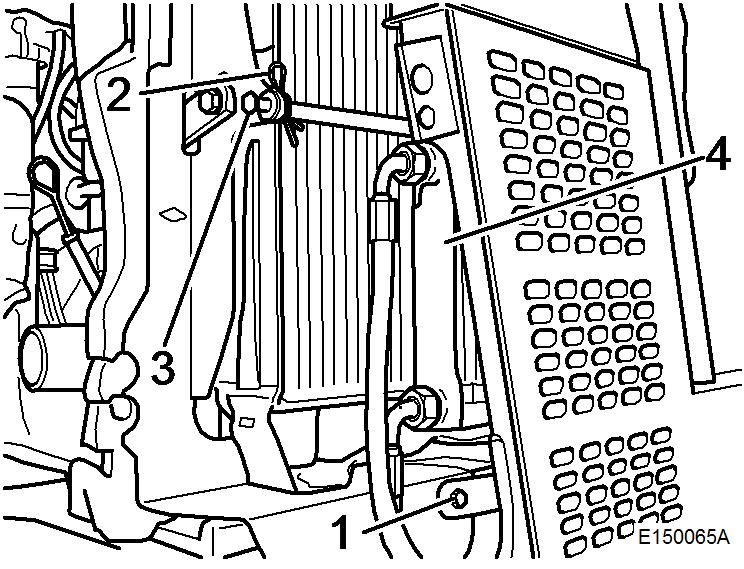
28. Unscrew both screws (1) and take off the radiator grid (2).
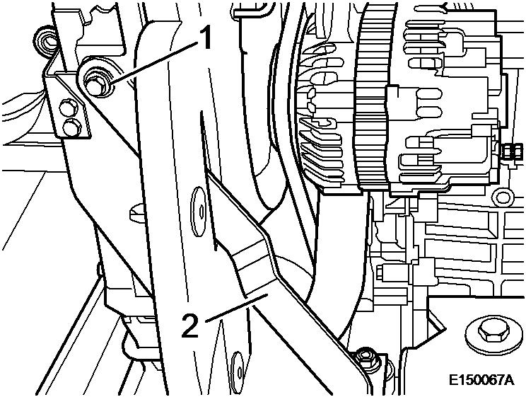
29. Unscrew screw (1) from both tie rods (2).
30. Unscrew screw (1) from support (2).
31. Remove screws (3) from the exhaust flange.
32. Unscrew screws (4 and arrow) and take off the complete exhaust system.
Figure 12
Figure 13
Figure 14
33. Unscrew both screws (5) of the front engine suspension.
34. Unscrew both screws (1) of the rear engine suspension.
35. Take the engine out of the engine carrier.
Weight: approx. 125 kg
Document Title: Function Group: Information Type: Date:
Specification, engine 200 Service Information 2014/6/22
Profile:
Specification, engine
Specification, filling capacities
Suggest:
If the above button click is invalid.
Please download this document first, and then click the above link to download the complete manual.
Thank you so much for reading

Specification, weight