
Description
Profile:
Description
The EC25 is powered by a 3-cylinder four-stroke diesel inline engine.

Document Title: Function Group: Information Type: Date: Installing the engine 200 Service Information 2014/4/17
Profile:
Installing the engine
Op nbr 2101
Lifting sling 1 m
Shackle 3/8""
1. Attach the lifting tackle to the engine. Weight approx. 125 kg.
2. Lift the engine into the machine.
NOTE!
Take care not to damage the hydraulic hoses.
3. Assemble the front left hand engine mounting. Cover the screws slightly with Loctite and tighten with 55 Nm.
4. Turn in the screws between engine mountings and rubber elements and tighten with 105 Nm.
5. Remove the lifting tackle to the engine.


2. Hydraulic pump
6. Install compensation tank bracket and engine hood lock.
7. Mount the hydraulic pump and tighten the screws with 105 Nm.
8. Fasten both brackets with hydraulic hoses to the rear engine mounts.
9. Assemble fan grid and heating hose bracket to the engine mounting.

10. Install heating and coolant hoses with new hose clamps.
11. Fasten the throttle control to the injection pump.
Engine block fastening screws Fastening screw Exhaust muffler bracket Traverse
12. Install the engine wiring loom and connect the following components:
Oil pressure switch
Fasten the cables with cable straps.
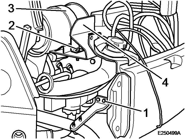
13. Assemble the exhaust muffler traverse.
14. Install the exhaust system, attach bracket (3) and tighten screw (2) with 85 Nm.
15. Fasten the exhaust bracket on the engine block and tighten screws (1) with 25 Nm.
Figure 3 1. 2. 3. 4.16. Install the air filter with bracket and tighten the screws with 24 Nm.
17. Connect the electrical cables and terminals to the following components:
Fuel pump
Air filter vacuum gauge
Fasten the cables with cable straps.
18. Reconnect the fuel pipes.

19. Set the valve lever on the fuel pre-cleaner to position OPEN.
20. Fill in coolant. Filling capacity: approx. 6 litres.
21. Connect the ground cable to the battery.
22. Fold the lateral weight back in and fasten with screws.
23. Assemble engine hood and floor plate.
24. Start the engine and make sure that there are no leaks.
Figure 4Oil
Coolant

Performance characteristics (measuring values for one hour with fan)


Document Title: Function Group: Information Type: Date: Removing the engine 200 Service Information 2014/4/17

Profile:
Removing the engine
Op nbr 2101
Lifting sling 1 m Shackle 3/8""
1. Disassemble engine hood and floor plate.
2. Unscrew the bolts from the lateral weights and pull the weights out.
3. Disconnect the ground cable from the battery.
WARNING
When opening the lid of the compensation tank (radiator cap) there is a risk of scalding because of the overpressure in the cooling system.
4. Unscrew the drain plug, open the radiator cap and drain of all coolant. Filling quantity approx. 6 litres.
6. Disassemble the fuel pipes.
7. Disconnect all necessary electrical cables and terminals from the following components:
Socket Fuel pump Air filter vacuum gauge
8. Unscrew the top and bottom fastening screws from the bracket and remove the complete air filter.
Engine block fastening screws
Fastening screw
Exhaust muffler bracket Traverse
9. Remove the exhaust silencer from the exhaust tube.
10. Unscrew the fastening screws from bracket and engine block and remove the exhaust system.
11. Disassemble the exhaust muffler traverse.
12. Disconnect all necessary electrical cables and terminals from the following components:
Oil pressure switch Injection pump Glow plug
Temperature sensor Generator Starter Ground cable
13. Lay the engine wiring loom to the side.

14. Disconnect the throttle control from the injection pump.
15. Remove the heating hose bracket from the engine mounting.
16. Disassemble heating and coolant hoses.
17. Remove the fan grid.
18. Disassemble both brackets for hydraulic hoses from the rear engine mounts.
19. Remove the hydraulic pump from the engine.
20. Unscrew the screws between engine mounts and rubber elements.
21. Remove front left hand engine mounting, compensation tank bracket and engine hood lock.
1.
2. Lifting sling 1 m Shackle 3/8""
22. Attach the lifting tackle to the engine.
23. Lift the engine out.
Weight: approx. 125 kg
Figure 5 Attach the lifting tackleDocument Title: Function Group: Information Type: Date: Specification, engine 200 Service Information 2014/4/17
Specification, engine
Specification, filling capacities
Specification, weight
Document

Starter side
Document Title: Function Group: Information Type:
Tightening torque
Document
Profile:
Valve timing
Technical data, general
Valve system
Valve clearance (warm or cold engine)
Document Title:
Profile:
Checking the compression pressure
Op nbr
ST332270 Adapter for pressure gauge
1. Set the control lever to a position in which the fuel supply is interrupted.

2. Disassemble all glow plugs and install adapter (1) ST332270 with pressure gauge (2) to one of the cylinders.
3. Crank the engine with the starter.
Compression pressure, see table [Invalid linktarget]
The measured compression pressure depends on the starter speed during the measuring process and the altitude of the engine location.
Limit values can therefore not be specified precisely. The compression pressure measurement is only recommended as a comparison measurement for all cylinders of an engine. If a deviation of more than 10% is found the respective cylinders should be disassembled in order to detect the cause.
4. Insert all glow plugs and tighten with 17.2 ± 2.5 Nm.
Adjusting the valves
NOTE!
Before starting adjustment work clean the area around the rocker cover.
1. Pull off the crankcase ventilation hose.
2. Remove the rocker cover.
3. Crank the engine until the valves are overlapping. NOTE!

Overlapping of valves means: Exhaust valve not yet closed, intake valve starts to open. Both push rods cannot be turned.

4. Adjust the valve clearance on the respective cylinder with a feeler gauge ( [Invalid linktarget] )
5. Tighten the counter nut. Check the adjustment once again with a feeler gauge.
Suggest:
If the above button click is invalid.
Please download this document first, and then click the above link to download the complete manual.
Thank you so much for reading

6. Attach the gasket to the rocker cover.
7. Fasten the rocker cover. Tighten the screws with a torque of 11.3 Nm.
8. Plug on the crankcase ventilation hose.