Kama Koska PORTFOLIO

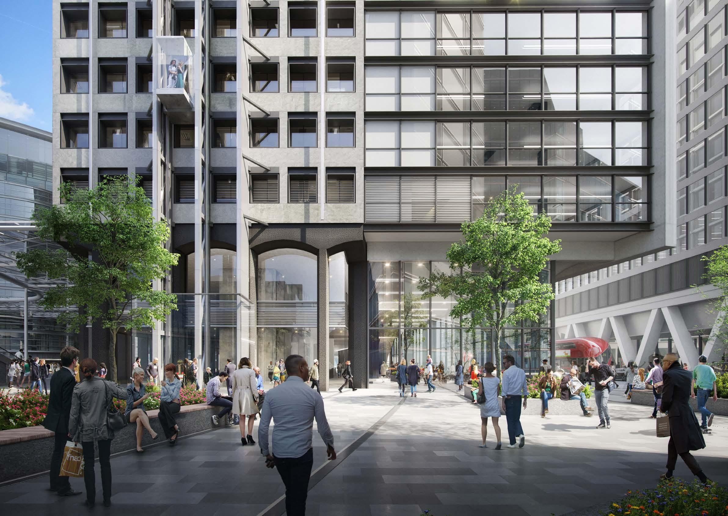
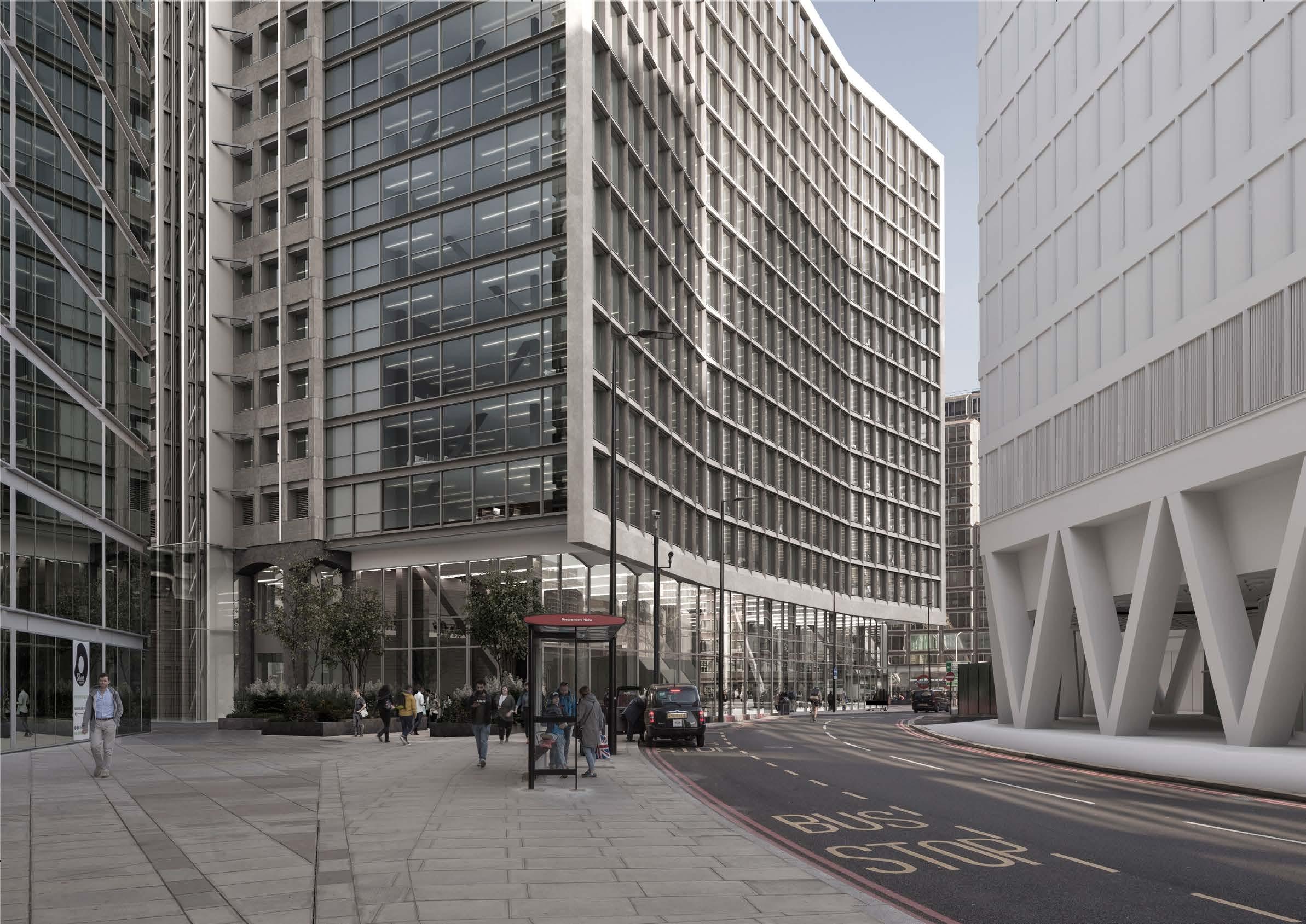
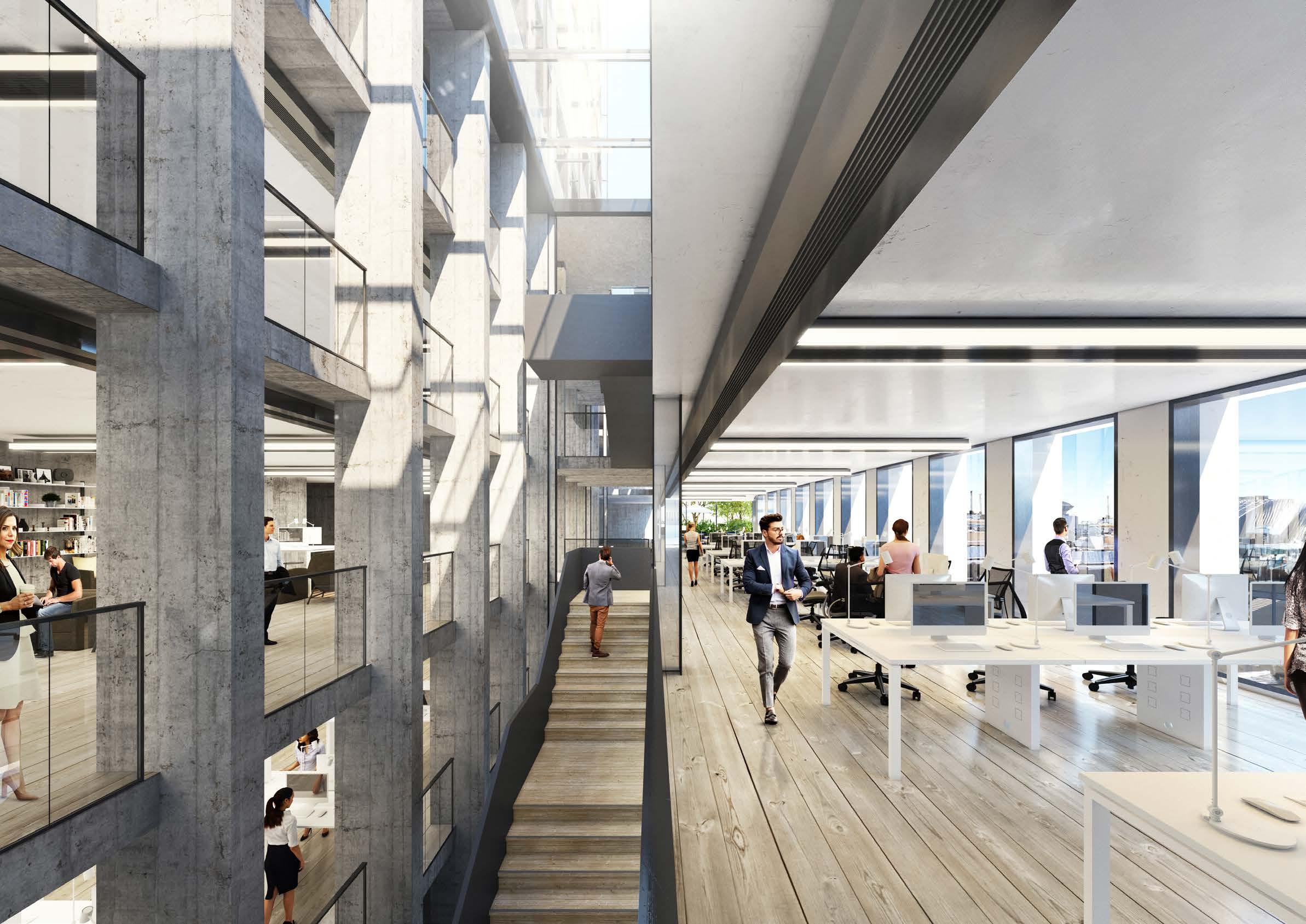
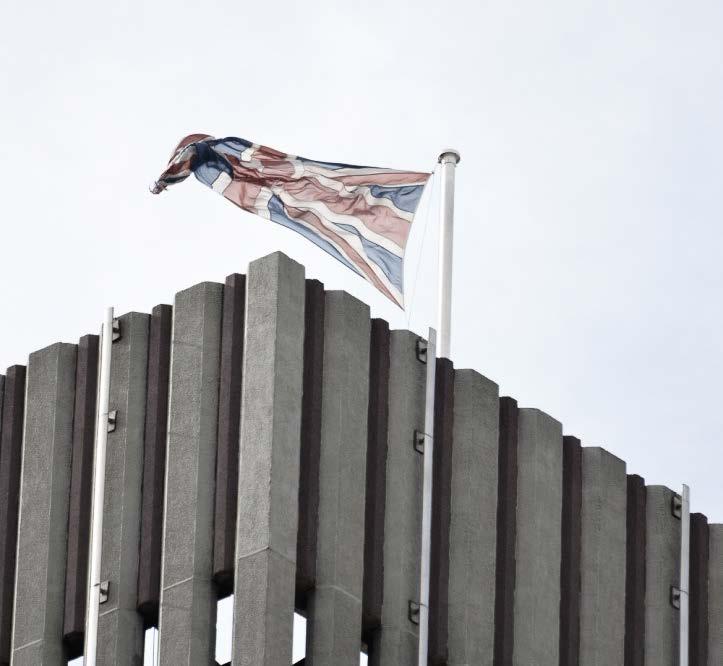
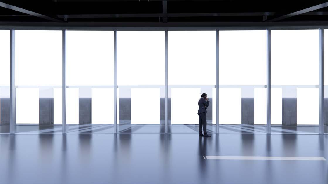
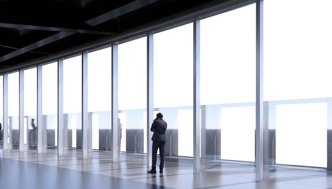
Landsec appointed Gensler for architecture and landscape design services together with the rest of the design team to reposition Portland House. The task was to revitalise the existing 1960s commercial building, to refurbish the office space and to clean the building’s facade to celebrate its heritage. The existing public realm has many obstacles and level changes which needed to be addressed. The barriers and existing street clutter had to be removed and the level changes made even to create a more permeable ground floor and inviting public realm.
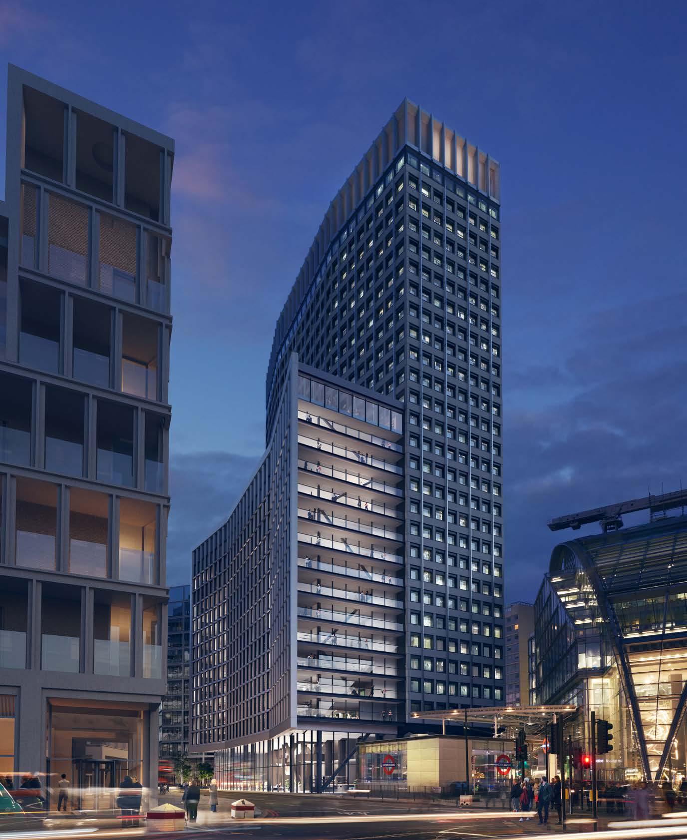
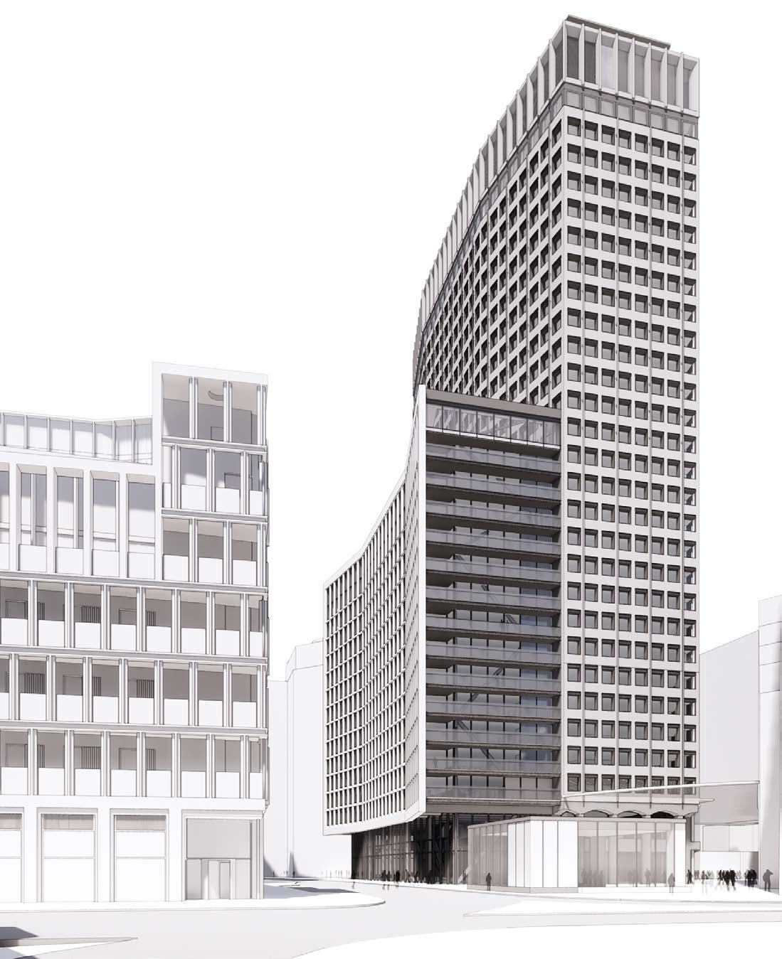
On top of that we have introduced a new massing of 15 storeys from Bressenden Place to provide more flexible office space in the heart of Victoria. The program included an accessible rooftop restaurant and bar, offering a new destination with views across the Capital. The ambition for the development is to set a new standard for sustainable office buildings in Westminster. The repositioning of Portland House is an opportunity to understand that the current tall building has to make an impact. The vision for the design is to:
• Create a building that demonstrates exemplary standards in the renovation of existing structures in terms of energy performance and wellbeing, which can serve as an example to others.
• Deliver an ecologically-focused ultra-low carbon development with minimised demand met by clean energy systems.
• Demonstrate reductions in greenhouse gas emissions through design, procurement and construction, with a clear focus on driving embodied carbon reductions.
• Incorporate circular economic principles and strategies, challenging the use of resources and the concept of waste, improving resource efficiency and designing for longevity.
• Deliver a design that inspires ecologically sound behaviour and serves as a symbol for the surroundings at all scales.
vs
Demolish everything Build new Addition and adaption
Portland House
REPOSITIONING REDEVELOPMENT
Client: LANDSEC PORTLAND HOUSE DEVELOPER LIMITED

Architect: GENSLER
Landscape Architect: GENSLER


Restaurant Experience: SNOHETTA
Planning Consultants: GERALD EVE

Structural engineers: ARUP

Sustainability + BREEAM: ARUP
Wind & Microclimate: ARUP
MEP engineers: WATKINS PAYNE
Wind Tunnel: RWDI
Flood risks & Water Resources: WATERMAN

Facade Consultant: FMDC


Facade Access and Maintenance: D2E
Gensler
Vertical Transportation: D2E
Cost consultants: GARDINER & THEOBALD

Traffic, Transport & Waste Management: MOMENTUM
Ecology: GREENGAGE ENVIRONMENTAL
Fire consultants: EXOVA Noise: HANN TUCKER

Townscape Assessment: TURLEY
Consultation: KANDA CONSULTING

Verified views: MILLER HARE
Cycle Facilities: FIVE AT HEART

Daylight and Sunlight: POINT 2
Daylight Analysis: an-imo
The Team
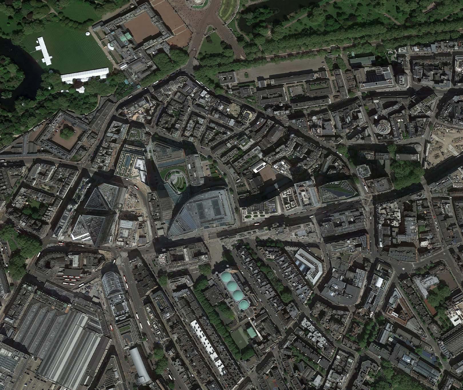
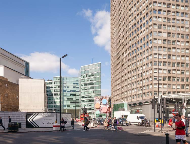
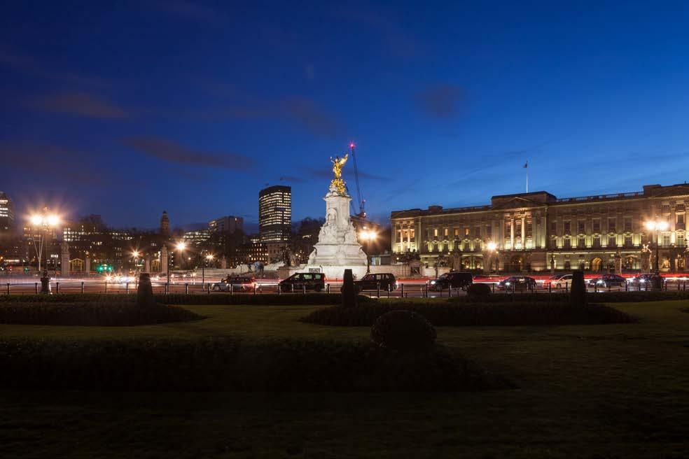
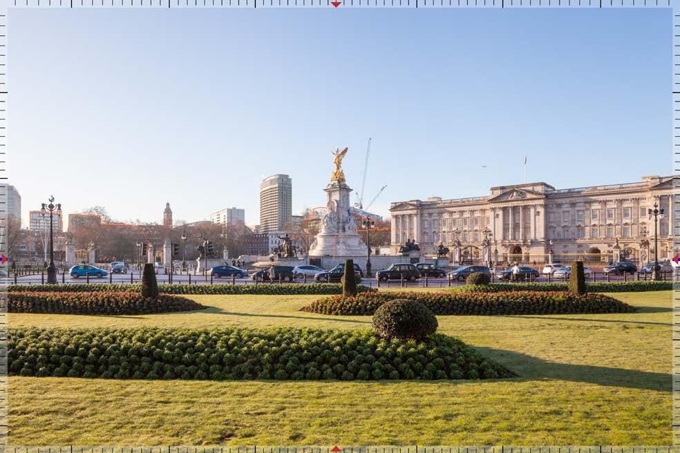
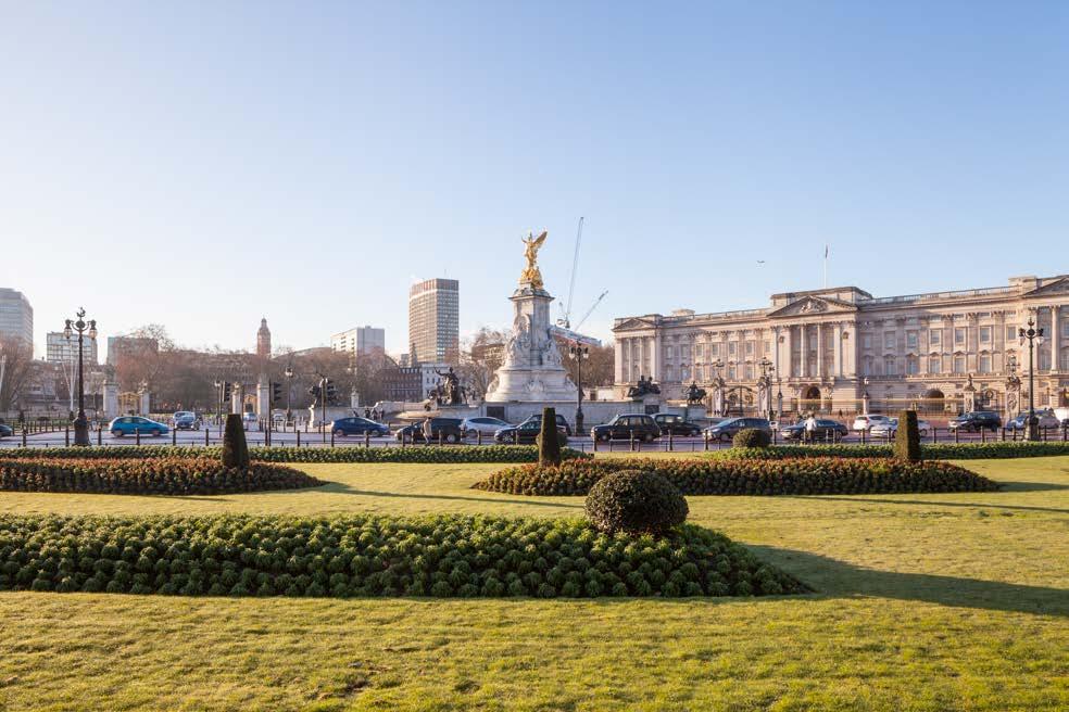
Portland House is located on Bressenden Place in Victoria, within the City of Westminster. Victoria Station, just 5 minutes walk away, is London’s busiest transport interchange.
 Victoria St.
Bressenden Pl
Buckingham Palace
PORTLAND HOUSE
Victoria Station
St James’ Park Station
Vauxhall BridgeRd
Nova Place
Victoria St.
Bressenden Pl
Buckingham Palace
PORTLAND HOUSE
Victoria Station
St James’ Park Station
Vauxhall BridgeRd
Nova Place
Location
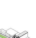
Aerial view of the site
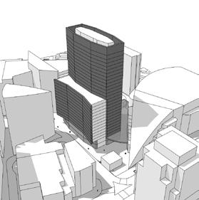
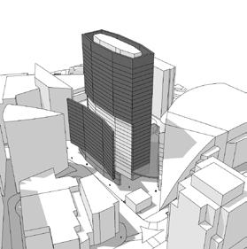
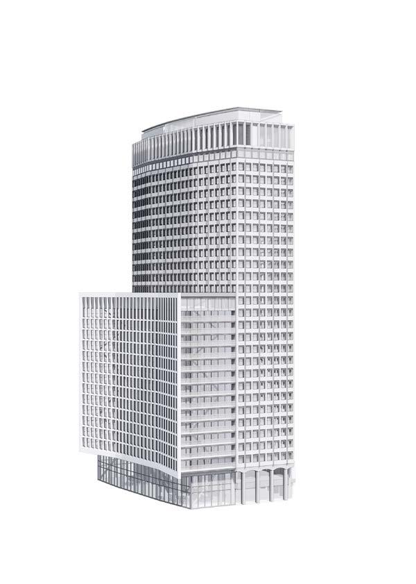
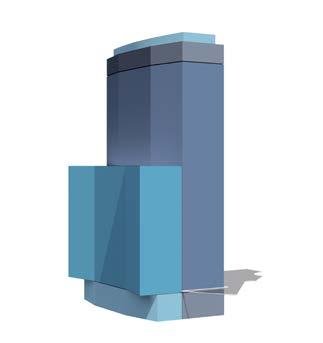
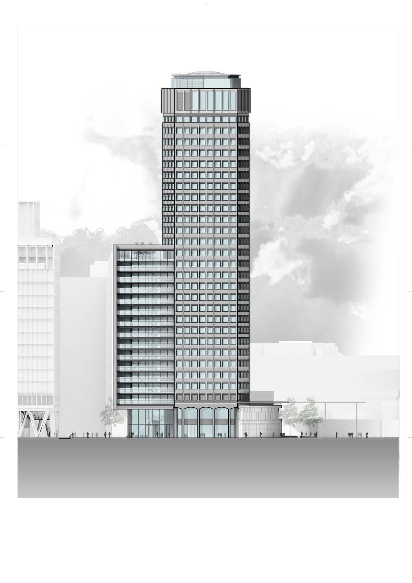
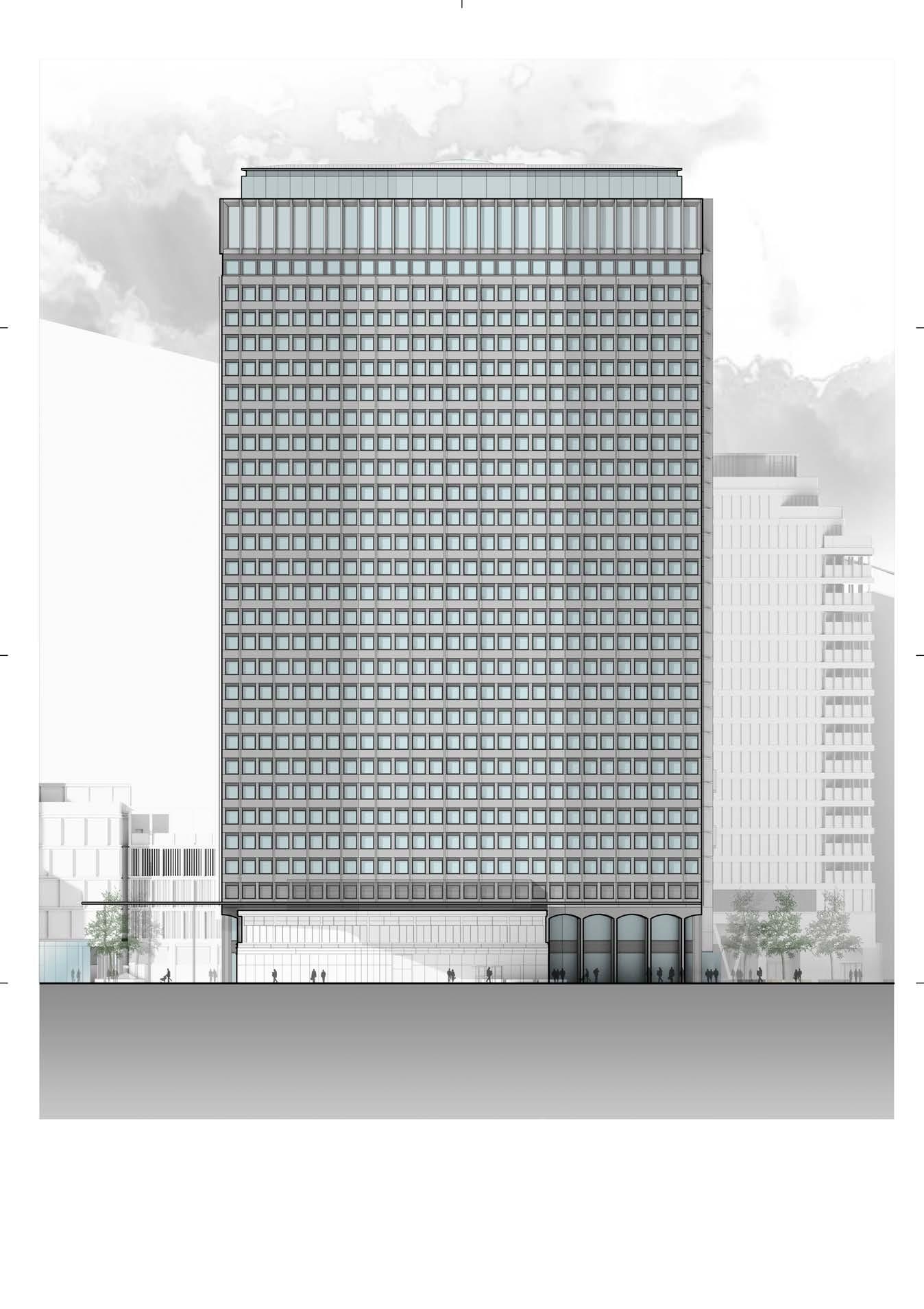
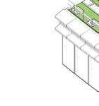
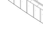
The proposal sees the opening-up of the facade on Bressenden Place and the reversal of its geometry to respect the curve of the road.
Symmetry and equidistant proportions are important for the integrity of the existing building. The scale of the proposed extension has been carefully considered. It was essential that the extension responds
Existing Proposed
Eq Eq
Eq Eq Eq Eq Eq Eq Eq Eq Eq Eq Eq Eq Eq Eq 2. DISPLACING THE WALL 1. EXISTING 3. INVERTING THE GEOMETRY ABOVE STREET LEVEL 4. FILLING THE IN-BETWEEN SPACE
Massing Strategy
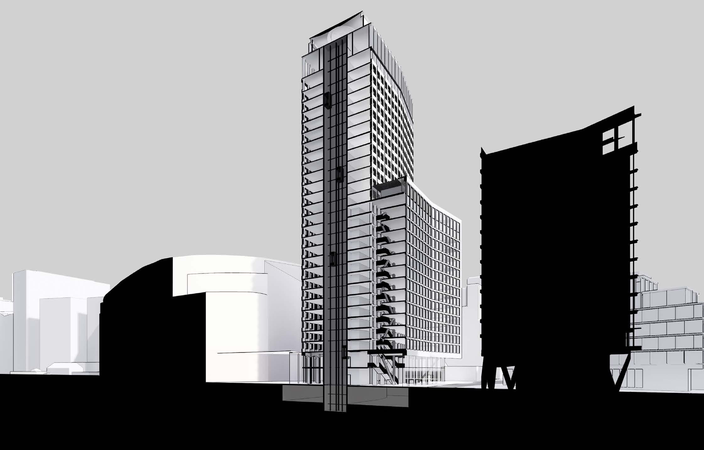
Height & Relationship with Context
The extension respects the height of neighbouring buildings, in particular Eland House and 171 Victoria Street, and has been carefully tested in townscape and strategic views which have been presented in the planning submission.
Surrounding townscape building heights
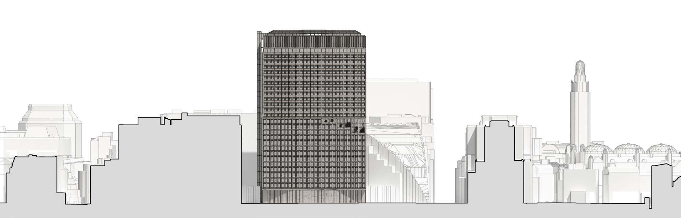
Eland House 171 Victoria Street Victoria Street
Cardinal Place
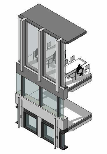
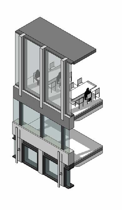
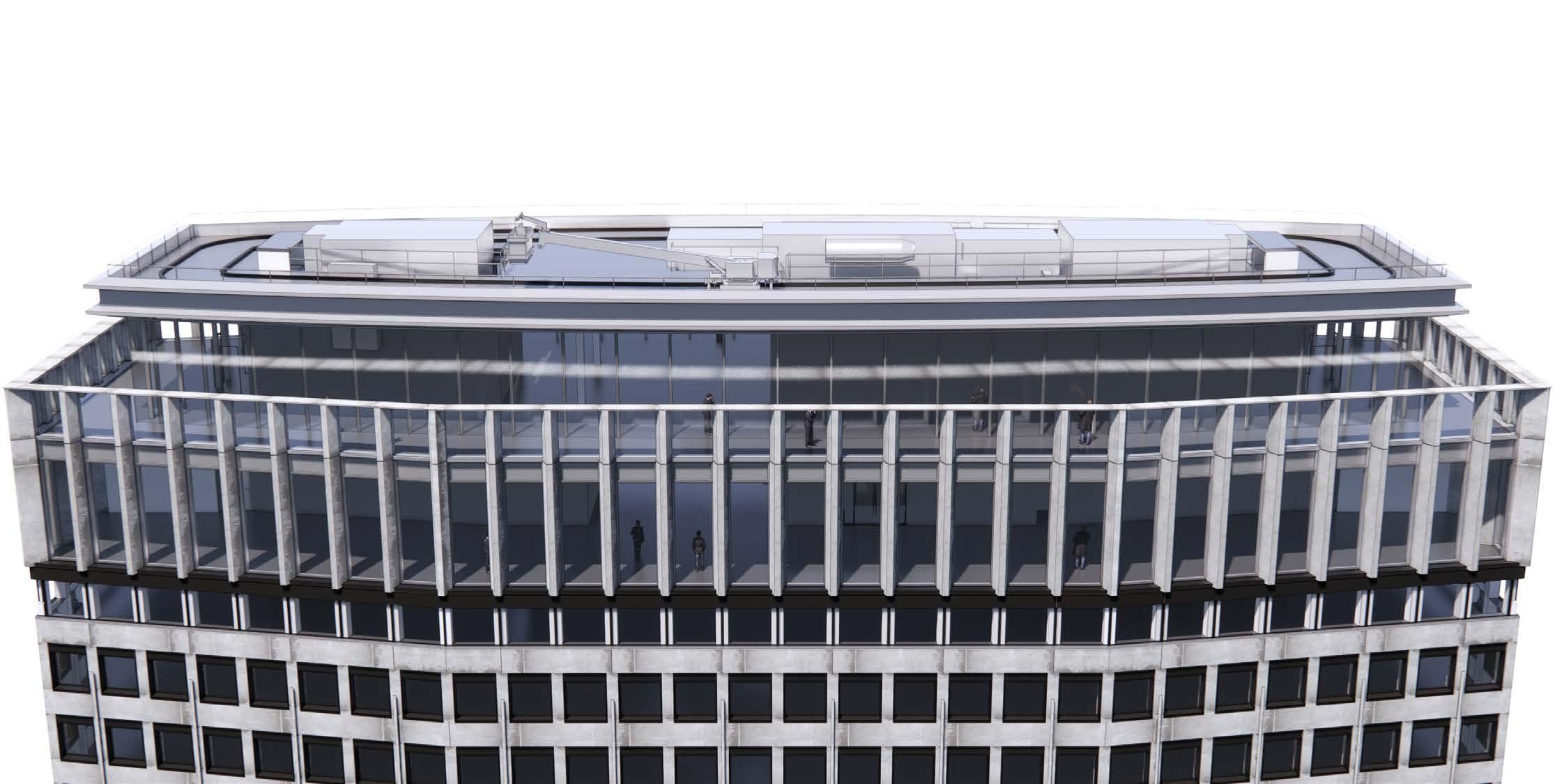
The new intervention will consist of an office extension up to level 14, including the extension of the lobby into a double height space connecting ground and first floor; and a new rooftop destination for food & beverage.
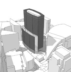
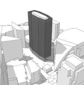
In order to accommodate these changes some interventions to the existing building will take place, altering its massing. A partial removal of the West facade and complete removal of the building crown will need to take place.
EXISTING BUILDING INTERVENTION PROPOSAL
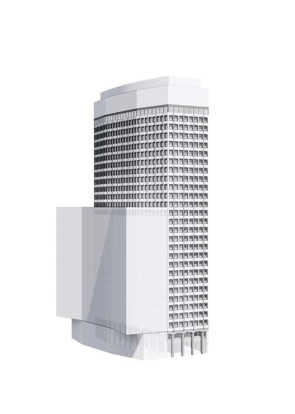
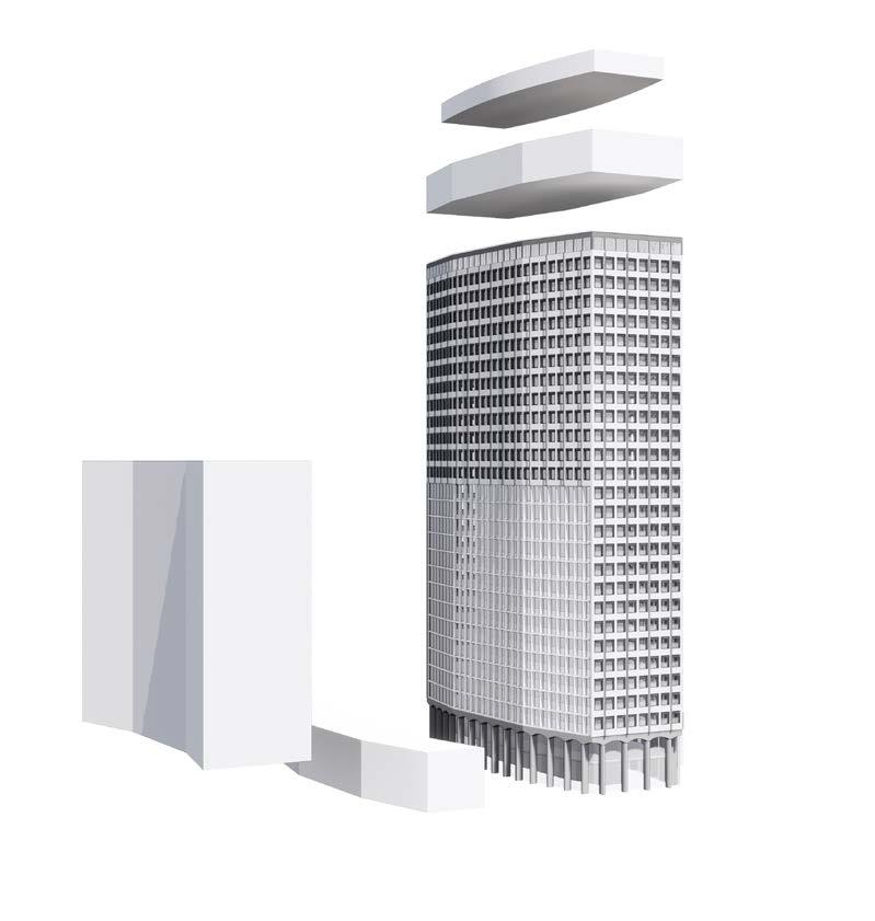
NEW MASSING EXTENTS
Rooftop Bar
Rooftop Restaurant
Office Extension
Ground Floor Extension
Massing & Brief
TOP OF THE BUILDING LEVEL 29 LEVEL 28 LEVEL 15 RESTAURANT & BAR OFFICE AMENITIES & TERRACE THE BASE LEVEL 1 & GROUND
Sectional Perspective
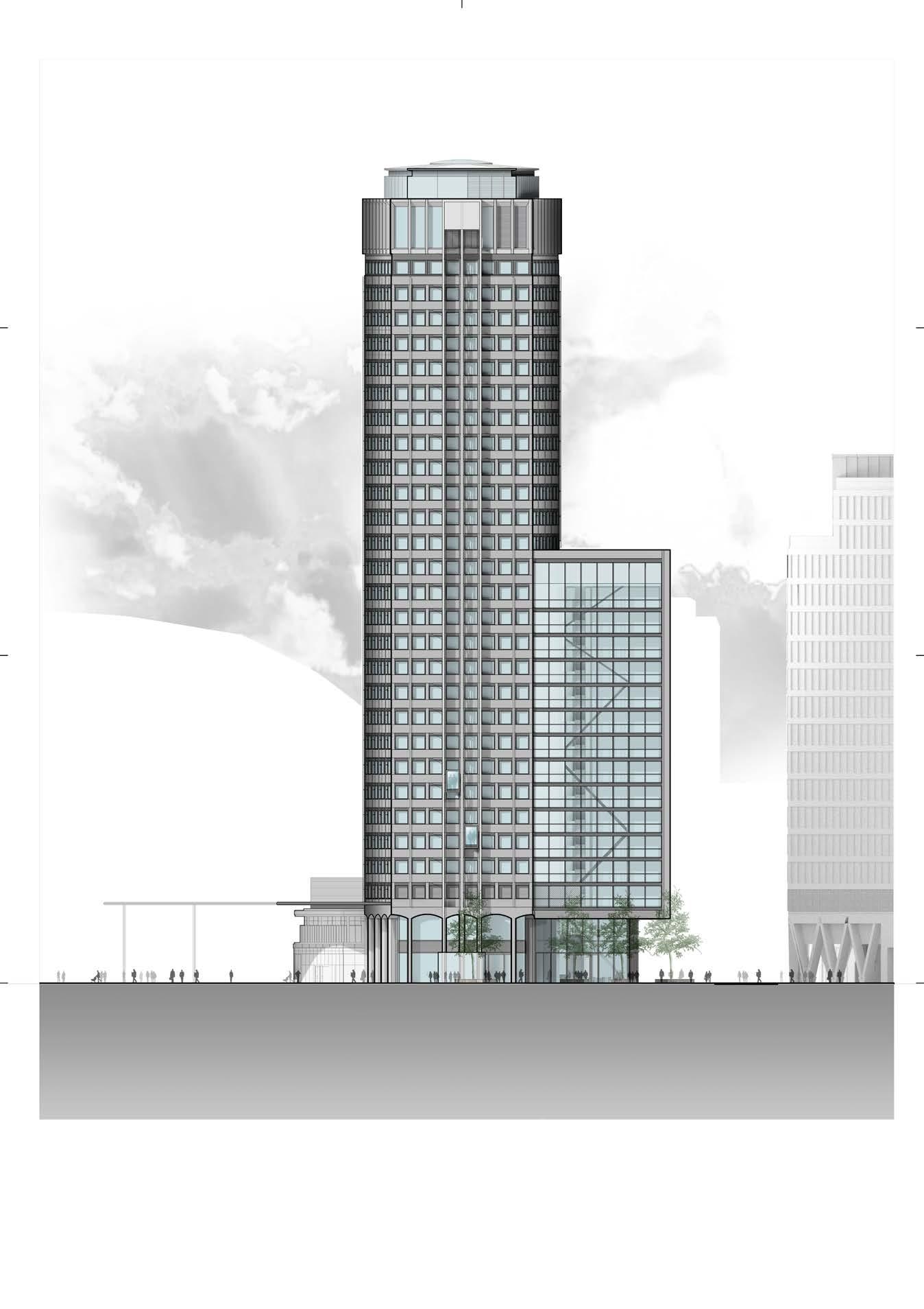
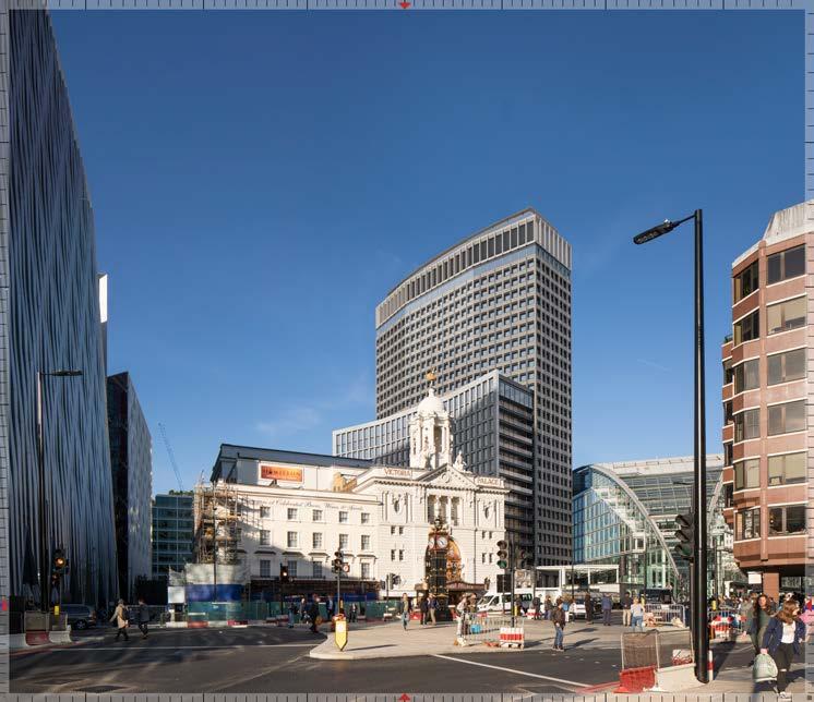
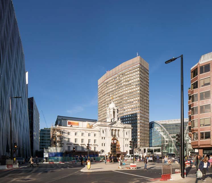
 View from the North
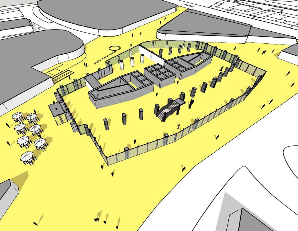
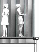
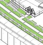
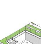
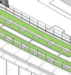
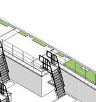
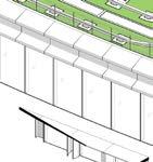
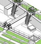
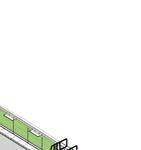
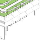
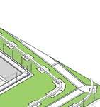
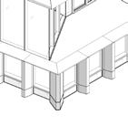
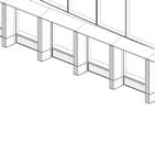
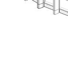
Portland House is surrounded by urban objects and obstacles that act as a barrier to its surroundings, and disrupt important pedestrian passageways.
Through the public realm enhancements, the proposal removed a number of urban obstacles and consolidated others within the building creating a coherent and permeable space which benefts from an improved pedestrian fow. To achieve this, level access is provided in addition to the streamlining of the immediate public realm.
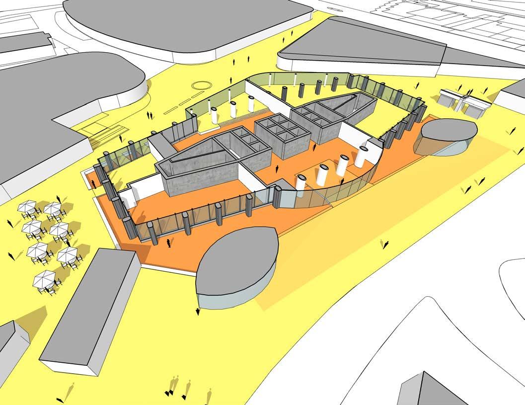
Existing obstacles Proposed improvements
0.00 m 0.00 m 0.00 m -0.25 m -0.50 m -0.50 m -0.50 m 0.00 m SLOPE ≈ 1:16 Current entrance to be replaced Gym & basement egress to be replaced Zephyr ventilation tower Gym Entrance to be replaced Sculpture to be removed 0.00 m -0.25 m -0.50 m 0.00 m -0.25 m -0.50 m
Public Realm Enhancement
Existing Proposed
• Acceptable conditions around most of the development
• Entrances show conditions above acceptable
• Business walking and distress conditions present towards the West
Wind Test Tunnel Results
Ambition to improve existing wind condtions in the surrounding
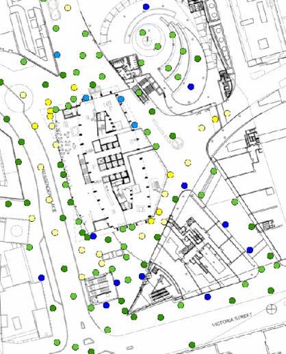
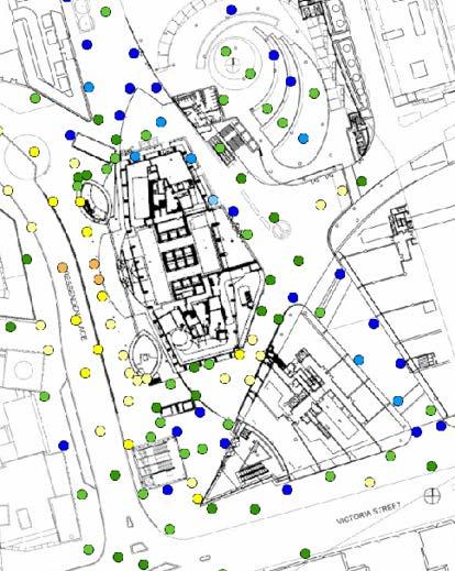
I took part in few wind tunnel tests at Milton Keynes to review the impact of wind on the surrounding. It was determined that the new massing improves existing conditions. Acceptable results were retained along the North passage in both summer and winter. The tests also confirmed acceptable ‘Standing’ and ‘Sitting’ conditions were achieved in summer, as shown below in the diagrams.
• ‘Strolling’ or better conditions around the entire development
• Additional mitigation can be added to improve areas for seating.
Sitting
Standing
Strolling
Comfort Criteria Business Walking
Distress limit for general public
Distress limit for able-bodied
Flow studies
The location of the main entrances to the building will determine the pedestrian flow within the lobby area. The aim is to keep areas as efficient as possible and also allow space provision for lounge areas and retail spaces. The journey of the visitor should be an enjoyable experience.
Wind tunnel test results supported the decision about final location of the entrance doors.
Main Access
Predominant flow Lobby Area
VENT TOWER VENT TOWER VENT TOWER VENT TOWER
North-South Access @ Existing Building
North-South Access @ Extension
North-South-West Access @ Existing Building
North-South-West Access @ Extension
Ground Floor Access
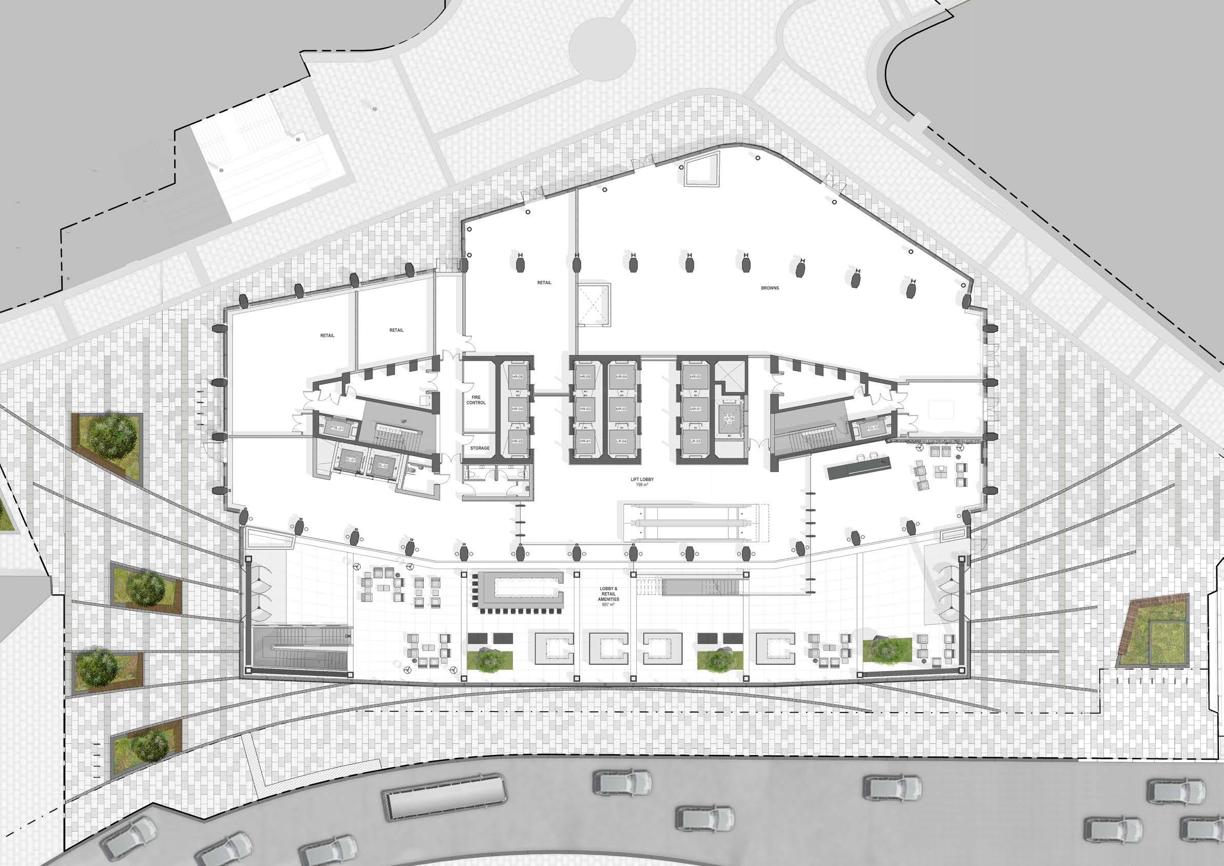
Ground Floor Plan BROWNS UKPN ACCESS RETAIL UNIT STAIR TO RETAIL BELOW RETAIL UNIT ROOFTOP RESTAURANT LOBBY FRONT DESK WAITING LOUNGE AREA LIFT LOBBIES
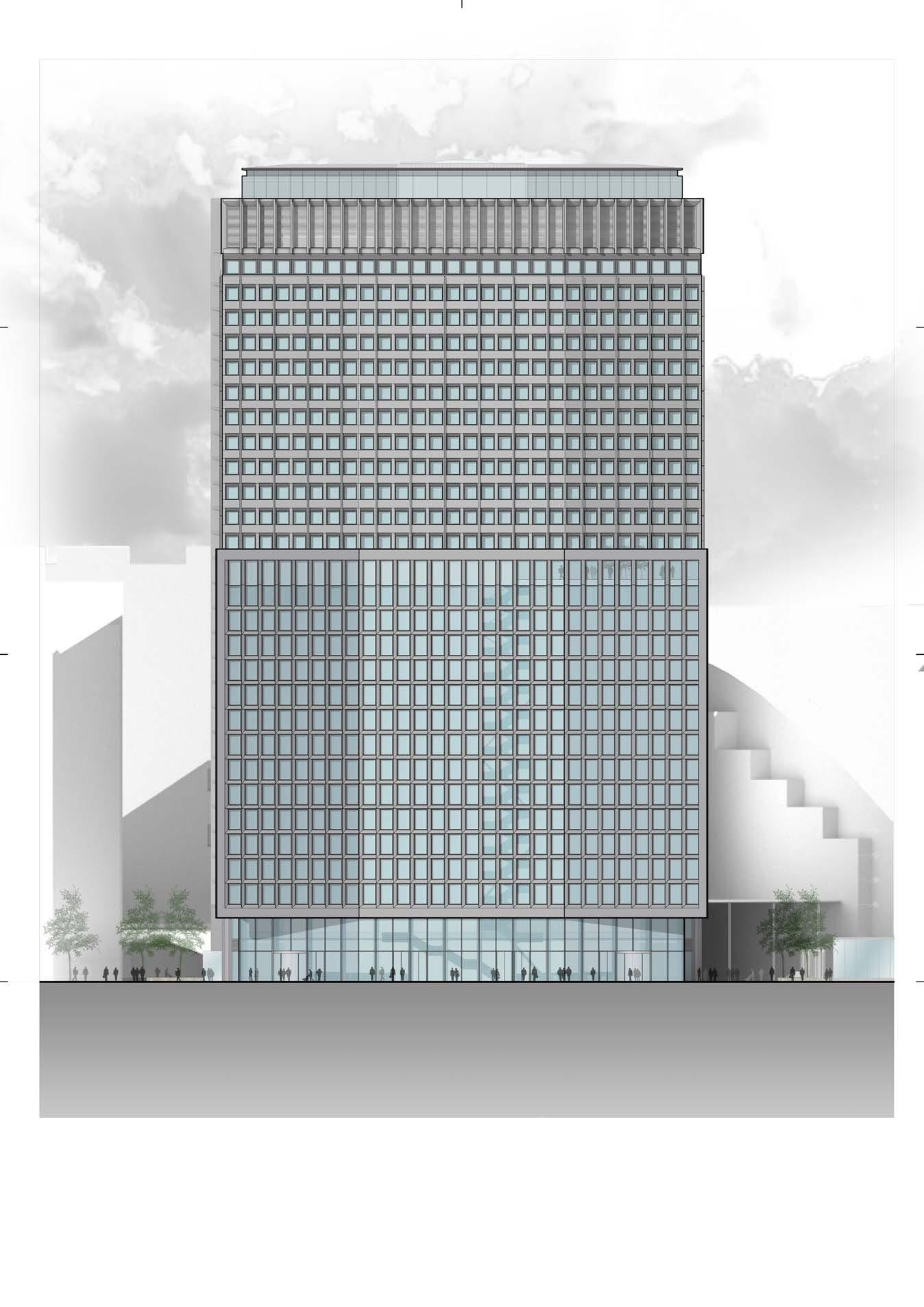
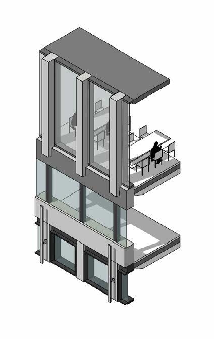
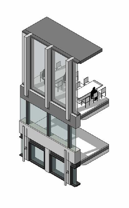
View from the North-West - Bressenden Place
Single Tenant
Tenant 01: 1,561sqm
Two Tenants
Tenant 01: 494 sqm
Tenant 02: 1,048 sqm
Three Tenants
Tenancy Splits
Typical Lower and Upper Levels
Tenant 01: 494 sqm
Tenant 02: 402 sqm
Tenant 03: 521 sqm
Single Tenant
Tenant 01: 979sqm
Two Tenants
Tenant 01: 480 sqm Tenant 02: 480 sqm
TENANT 01 TENANT 01 1561sqm TENANT 01 TENANT 02 TENANT 01 494sqm TENANT 02 1048sqm TENANT 01 TENANT 01 494qm TENANT 02 402sqm TENANT 03 521sqm TENANT 01 TENANT 01 979sqm TENANT 02 TENANT 01 TENANT 01 480sqm TENANT 02 480sqm
Typical Lower Levels
Test fit studies were carried out as a tool to understand the potential of the floorplate.
1:8m2 density
Level 3-14
Net Area 1,522 Sqm 16,383 Sf Seat Count (1.4m Desks) 190
Occupancy Density 1:8 Sqm 1:86 Sf
Support Spaces 524 Sqm 5,640 Sf % of Net Area 34%
Meeting rooms Collaboration areas Focus/phone booth Copy/print Vend/breakout Comms room Stores etc
1:6m2 density
Level 3-14
Net Area 1,522 Sqm 16,383 Sf Seat Count (1.4m Desks) 248
Occupancy Density 1:6 Sqm 1:66 Sf
Support Spaces 341 Sqm 3,671 Sf
% of Net Area 22%
Meeting rooms
Collaboration areas
Focus/phone booth Copy/print Vend/breakout Comms room Stores etc
wc wc GOODS LIFT GOODS LIFT PASS LIFT PASS LIFT PASS LIFT PASS LIFT PASS LIFT PASS LIFT PASS LIFT PASS LIFT
wc wc GOODS LIFT GOODS LIFT PASS LIFT PASS LIFT PASS LIFT PASS LIFT PASS LIFT PASS LIFT PASS LIFT PASS LIFT
Test Fits
Typical Upper Levels
Test fit studies were carried out as a tool to understand the potential of the floorplate.
1:8m2 density
Level 16-27
Net Area 959 Sqm 10,323 Sf Seat Count (1.4m Desks) 120
Occupancy Density 1:8 Sqm 1:86 Sf
Support Spaces 396 Sqm 4,263 Sf % of Net Area 41%
Meeting rooms Collaboration areas Focus/phone booth Copy/print Vend/breakout Comms room Stores etc
1:6m2 density
Level 16-27
Net Area 959 Sqm 10,323 Sf
Seat Count (1.4m Desks) 160
Occupancy Density 1:6 Sqm 1:65 Sf
Support Spaces 320 Sqm 3,444 Sf % of Net Area 33% Meeting rooms Collaboration areas Focus/phone booth Copy/print Vend/breakout Comms room Stores etc
PASS LIFT PASS LIFT PASS LIFT PASS LIFT PASS LIFT PASS LIFT GOODS LIFT GOODS LIFT
PASS LIFT PASS LIFT PASS LIFT PASS LIFT PASS LIFT PASS LIFT GOODS LIFT GOODS LIFT
Test Fits
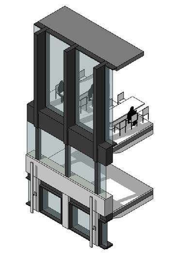
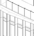
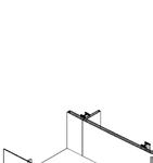
The new extension needs to be structurally independent from the existing building. In order to avoid placing concrete cores within the new office space, bracing elements have been proposed which combined with the column grid will provide the stability required.
These elements will be comprised of 2 vertical columns tied together with lateral elements. It is important that the columns do not land on top of the pile cap of the existing building but to work with a new piling system. The further apart these columns are, the better they will perform and support the new extension.
The proposed bracing configuration sits behind the glazed facade and presents the fewest diagonal elements, reducing the impact on office floor area and visual obstructions.
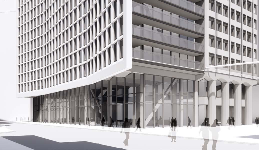
The pattern of the bracing contributes also as
a feature element, subtly present at the north and south facades, without overpowering the elevation. This is read as being part of the ‘mechanism’ of the new extension.
Extension Structure
Section North-South
Browns Rooftop Restaurant & Bar Retail Lobby / F&B / Retail Core Plant Office Amenities Terrace Office 0 4 10 20m TOB +111.050 Roof Edge +109.900 Level 29th +106.000 Level 27th +95.140 Level 16th +59.950 Level 2nd +15.140 Level 1st +10.350 Ground Floor Level +5.230
TOB +111.050
Roof Edge +109.900
Level 29th +106.000
Level 27th +95.140
Level 16th +59.950
Level 2nd +15.140
Level 1st +10.350
0 4 10 20m
Section East-West
Ground Floor Level +5.230 Browns Rooftop Restaurant & Bar Retail Lobby / F&B / Retail Core Plant Office Amenities Terrace Office
FLOOR FINISH MEP LINE CEILING FINISH DOUBLE GLAZING WINDOWS 250 250 2800 2500 300 150 150 FLOOR FINISH MEP LINE CEILING FINISH MOVEMENT JOINT 250 250 150 150 110 110 255 255 15 15 2830 2800 EXISTING PRECAST PANEL FLOOR FINISH INSULATION MEP LINE CEILING FINISH 110 110 110 110 255 255 15 15 2830 1000 1000
Sections
tower, new massing and movement
between existing and new massings
Typical
Existing
joint Movement joint
Section through existing tower Section through new massing
Old & New Office Floor
0 4 10 20m High Rise Passenger Lifts Mid Rise Passenger Lifts Low Rise Passenger Lifts Section B TOB Roof Edge Level 29th Level 27th Level 15th Level 2nd Level 1st GF Level Section B Section A A B A’ B’ The lift
British
Lift Performance
Rise Lifts High Rise Lifts Low Rise Lifts
performance studies took into consideration
Council for Offices (BCO) requirements for waiting times and time to destination.
Mid
Typical Low Rise Core
Typical Mid Rise Core
Lifts serving current floor
STREET
Typical High Rise Core
Mid Rise Passenger Lifts
100
High Rise Passenger Lifts Goods Lifts Low Rise Passenger Lifts
Typical Cores
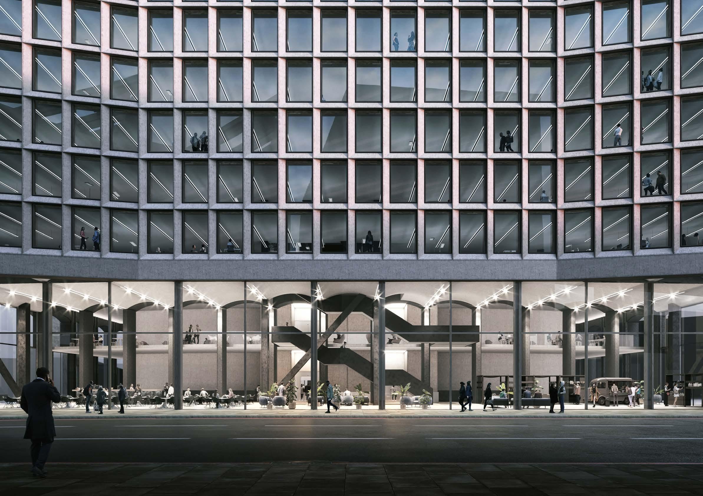
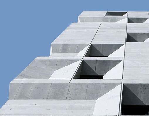
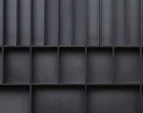
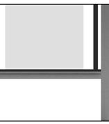
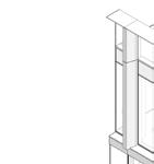
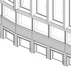
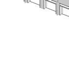
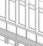
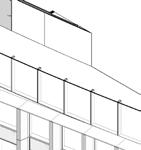
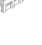
The material palette for the project is simple and has as few materials as possible. The existing brutalist building lacks contrast that depth and shadow would bring to the façade. Therefore, dark grey (almost black) metal is a good addition to the current palette.
At early stages of the design process, the façade was proposed to be made out of pre-cast concrete, however in order to reduce weight and therefore be able to control the depth of the façade the proposal is to use glass reinforced concrete (GRC).
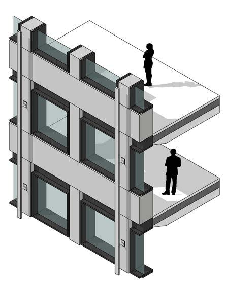
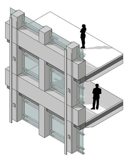
The existing pre-cast elements of the façade remain however all windows and sills are removed.
The existing facade of the tower is uplifted by:
• jet-wash / cleaning of the precast concrete elements
• sealing joints to be replaced
Existing Proposed
Facade Materiality Concrete and
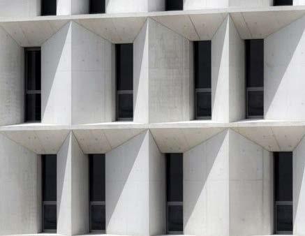
• new window systems
metal
• rails to be cleaned and potentially painted or capped
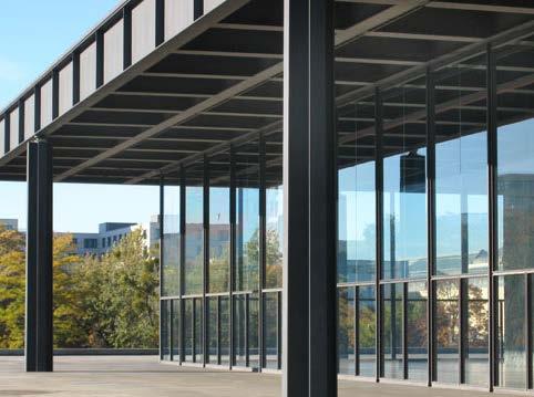
Neue Nationalgalerie, Berlin
Sheperds Building, London
Source: https://www.morrisand.company
Economics & Masters Building UNAV, Pamplona
Source: ArchDaily.com
Image by: Ruben Perz Bescos
Sipan Residential Building, Tehran
14 12 1 11 10 1 9 1 1 2 3 1 5 5 8 15 1 2 7 1 5 10 10 1 9 10 TOB +111.050 Roof Edge +109.900 Level 29th +106.000 Level 27th +95.140 Level 16th +59.950 Level 2nd +15.140 Level 1st +10.350 Ground Floor Level +5.230 TOB +111.050 Roof Edge +109.900 Level 29th +106.000 Level 27th +95.140 Level 16th +59.950 Level 2nd +15.140 Level 1st +10.350 Ground Floor Level +5.230 1 Proposed new glazing system 2 Proposed dark grey metal frame 3 Existing precast concrete panel 4 Existing stainless steel rail 5 Proposed insulated metal louvres 14 12 1 11 10 5 9 1 1 2 3 13 10 6 1 1 1 5 15 6 1 2 2 8 5 6 Proposed colour back-painted glass 7 Proposed photovoltaic laminated safety glass balustrade 8 Existing mosaic-clad concrete arches. 9 Proposed dark grey metal panel 10 Proposed glassfibre reinforced concrete panel 11 Proposed glass louvres 12 Proposed standing seam light grey metal roof 13 Proposed light grey metal cladding 14 Proposed operable glass roof 15 Proposed plant screen North and South Elevations
14 12 1 11 10 5 9 1 1 2 3 4 10 1 1 2 13 6 2 14 12 1 13 1 9 1 1 2 3 4 2 5 8 5 1 1 15 2 TOB +111.050 Roof Edge +109.900 Level 29th +106.000 Level 27th +95.140 Level 16th +59.950 Level 2nd +15.140 Level 1st +10.350 Ground Floor Level +5.230 TOB +111.050 Roof Edge +109.900 Level 29th +106.000 Level 27th +95.140 Level 16th +59.950 Level 2nd +15.140 Level 1st +10.350 Ground Floor Level +5.230 1 Proposed new glazing system 2 Proposed dark grey metal frame 3 Existing precast concrete panel 4 Existing stainless steel rail 5 Proposed insulated metal louvres 6 Proposed colour back-painted glass 7 Proposed photovoltaic laminated safety glass balustrade 8 Existing mosaic-clad concrete arches. 9 Proposed dark grey metal panel 10 Proposed glassfibre reinforced concrete panel 11 Proposed glass louvres 12 Proposed standing seam light grey metal roof 13 Proposed light grey metal cladding 14 Proposed operable glass roof 15 Proposed plant screen West and East Elevations
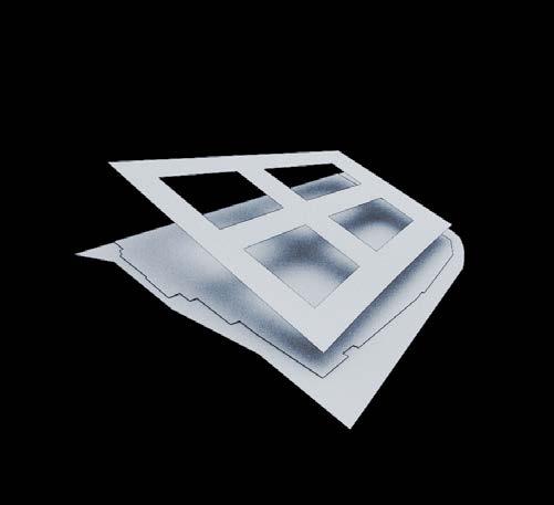
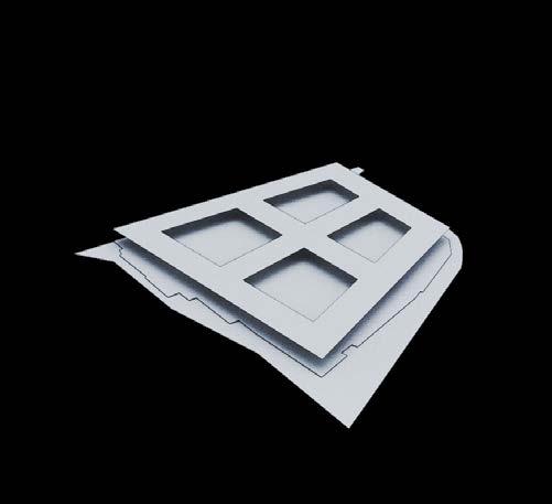
The Crown
AREA OF MY RESPONSIBILITY FROM STAGE
2
Unused opportunity
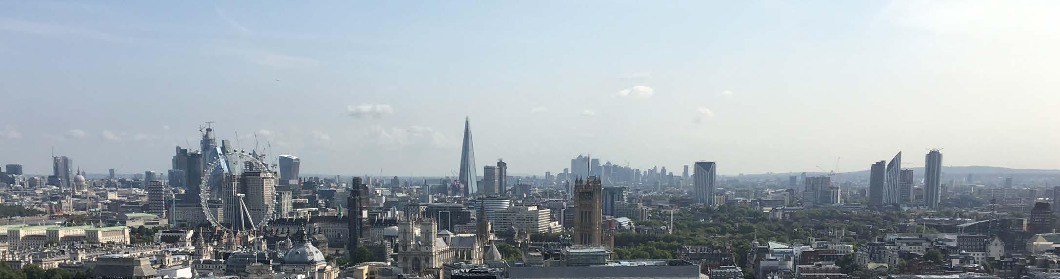
Portland House is currently the third tallest building in the City of Westminster. It is surpassed only by the Millbank Tower, completed in the same year (1963 )and the Victoria Tower of the
Palace of Westminster (1860), both located on the riverbank of the river Thames. The building presents uninterrupted views of the City of London, 360º all around the floorplates.
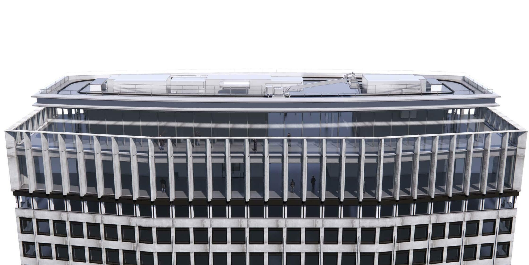
There is an opportunity to take advantage of the height and location of Portland House, creating a rooftop destination open for public access and delivering a new London experience.
To deliver this, the proposal consolidates the plant equipment located at the roof using the new
extension of the building and a new plant floor at level 2 to minimise the need for equipment at the top. By doing this, the remaining space can be repurposed for a rooftop restaurant & bar.
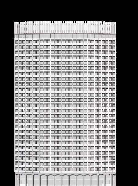
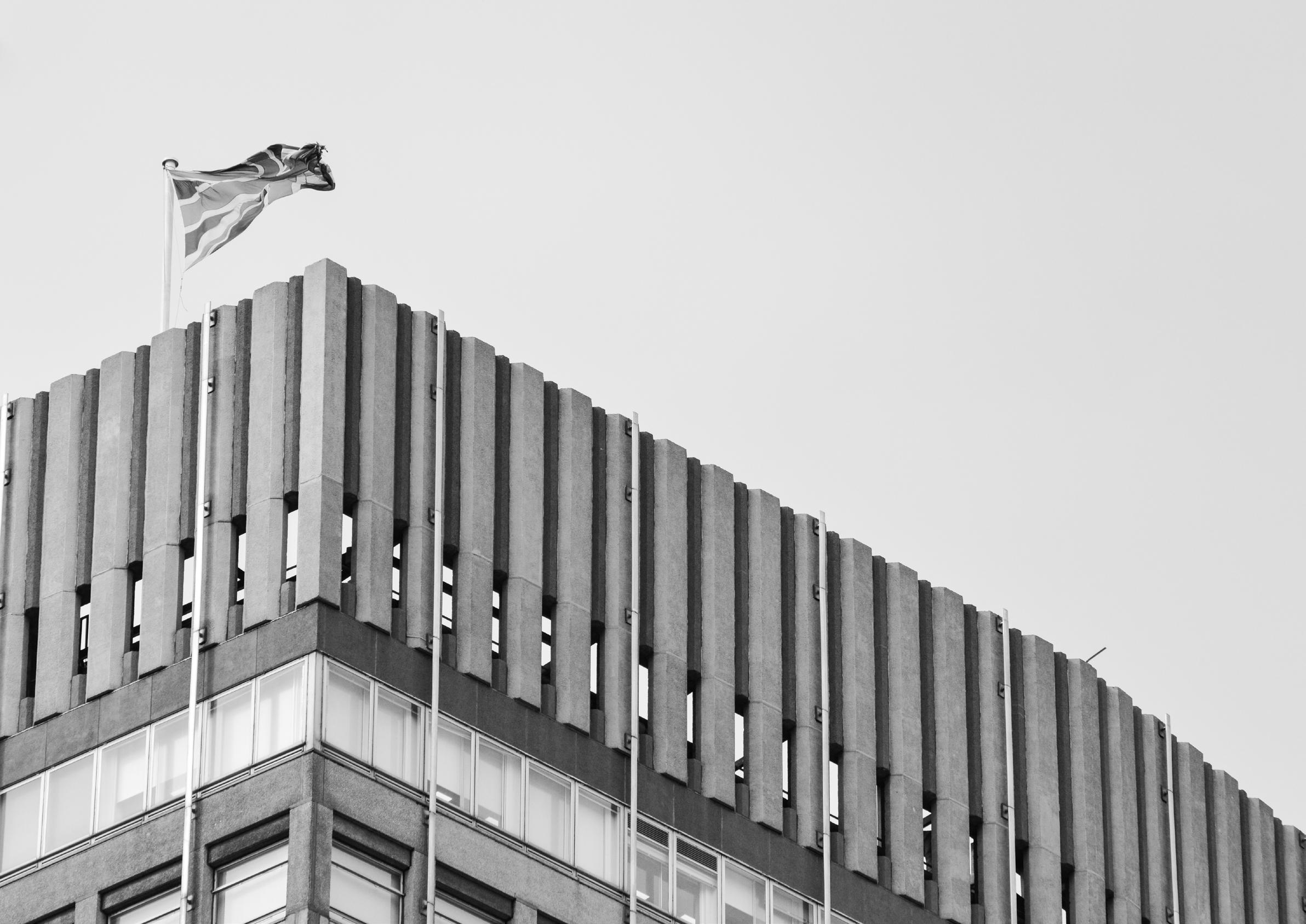
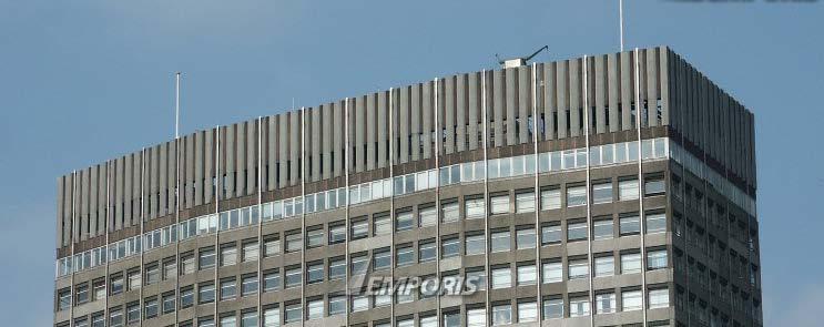
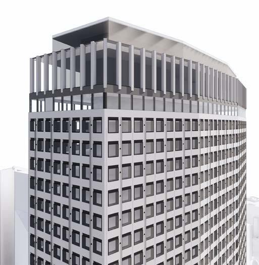
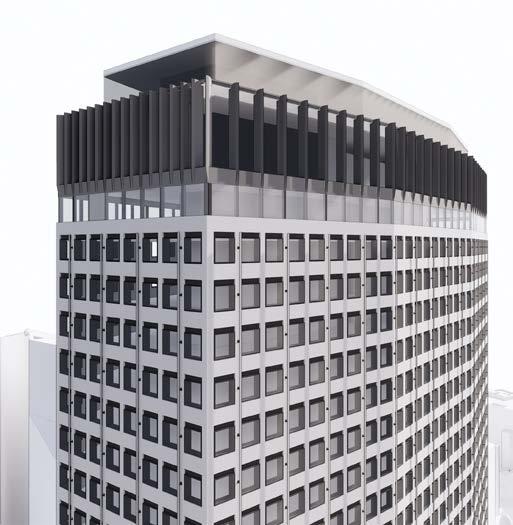
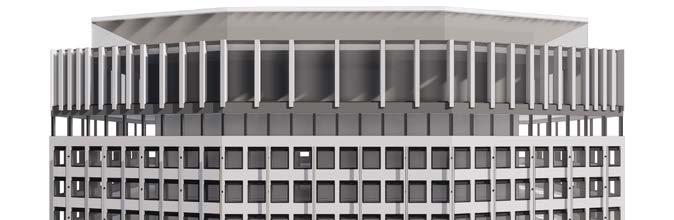
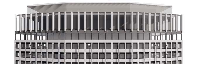
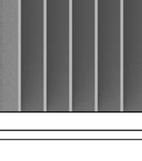
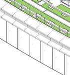
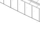
The existing tower terminates with a crown of closely spaced vertical precast concrete fins, that are appropriate to the current rooftop as an enclosure.
However, to change the function of the rooftop
means to rethink the crown so that it is an appropriate enclosure for new uses, and a meaningful conclusion to the top of the tower.
New vertical fins on the existing structural grid resonate with the previous expression, whilst
responding to depth increases and providing increased solar shading with a stronger rhythmic expression. Replacing heavy precast members with lighter weight fins releases load capacity for new rooftop uses.
STEP 1 RECREATE THE CROWN
STEP 2 CREATE AN ENCLOSURE
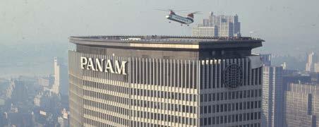
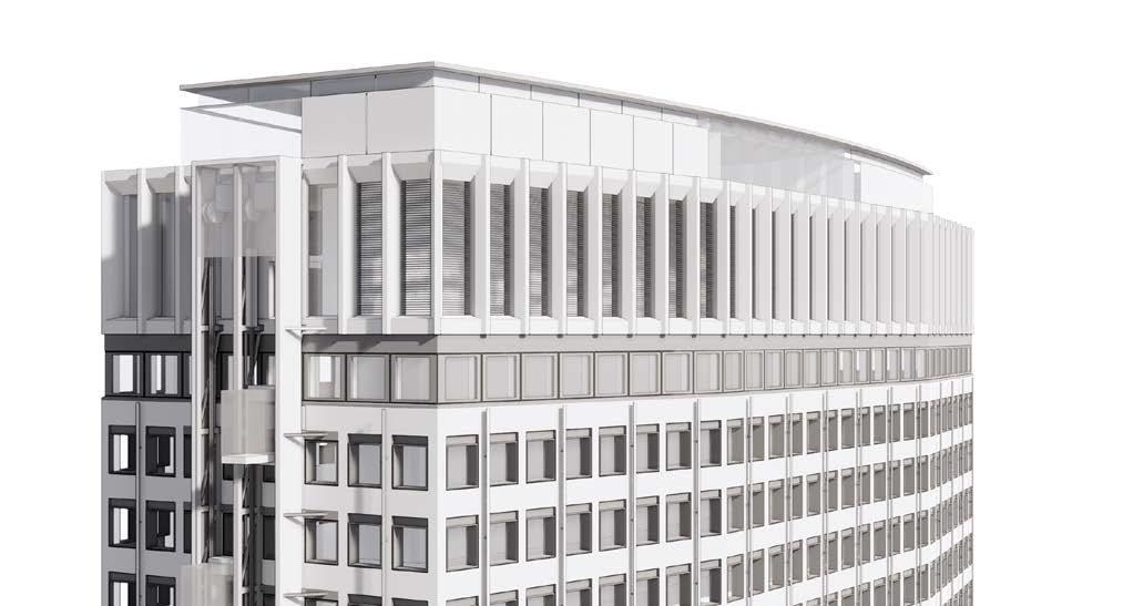
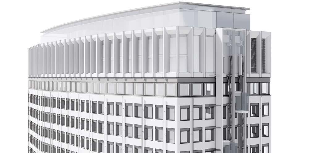
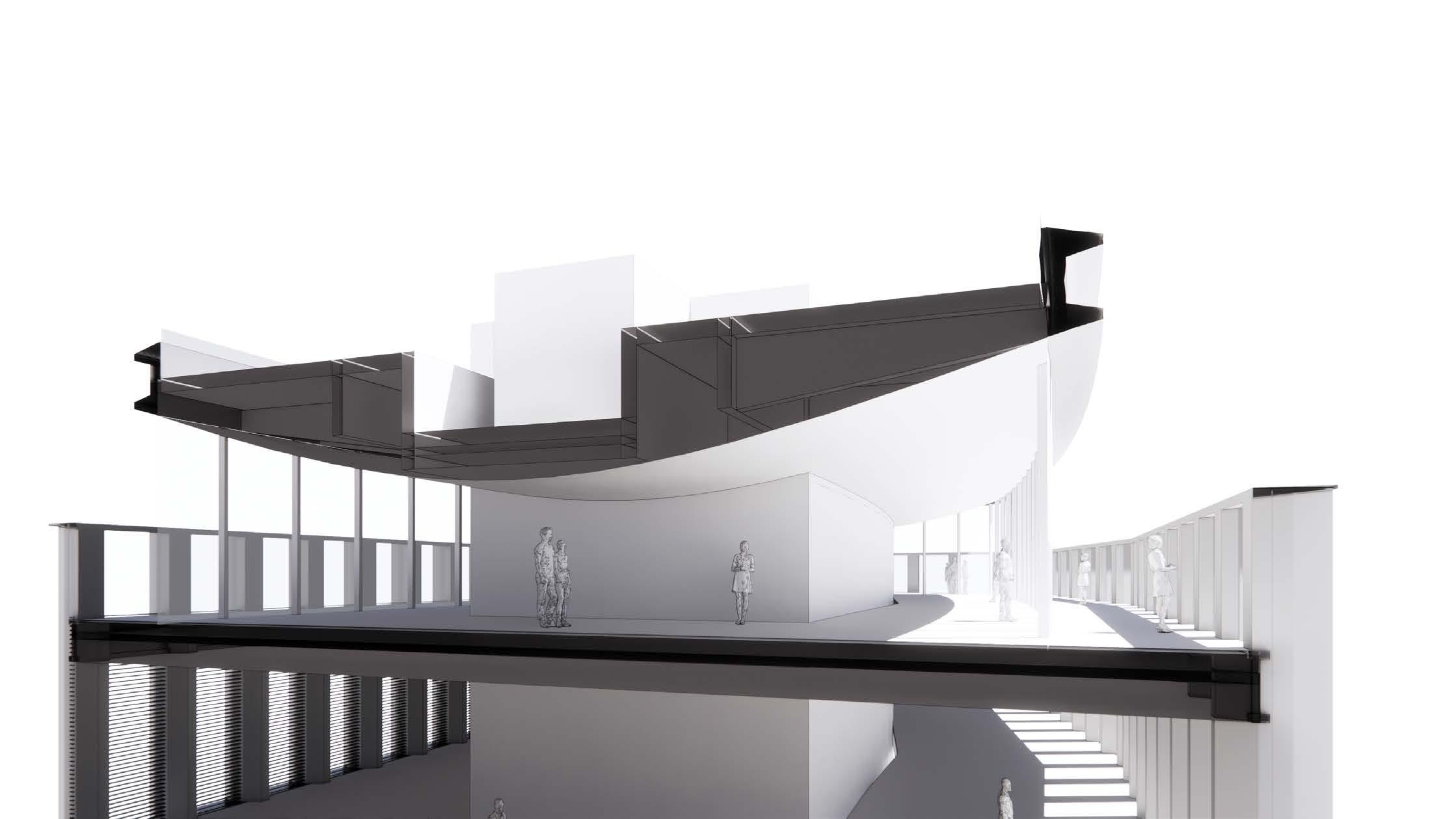
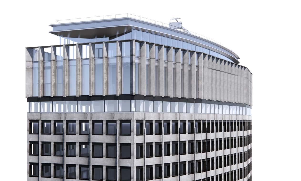
Atop the new crown is a new rooftop pavilionthe top level of the proposed panoramic rooftop restaurant.
Taking cues from Portland House’s sibling the Met-Life (Pan Am) building, a strong horizontal roof plane creates a more sensitive response to
the architecture and respects the integrity of the existing building. The calm horizontal line means that the massing appears integrated and not overtly emphasised, minimising the impact of the additional height.
 Met Life (Pan Am) Building - New York 1963
Portland House - London 1963
Met Life (Pan Am) Building - New York 1963
Portland House - London 1963
Rooftop Strategy
A series of studies have been undertaken in order to develop a position to identify the best approach to address uses, architectural and contextual requirements.
The challenge has been to get the top of the building to respond to the rigour of the rest of the building and achieve the important qualities identified by the team and the Council, such as symmetry and consistency.
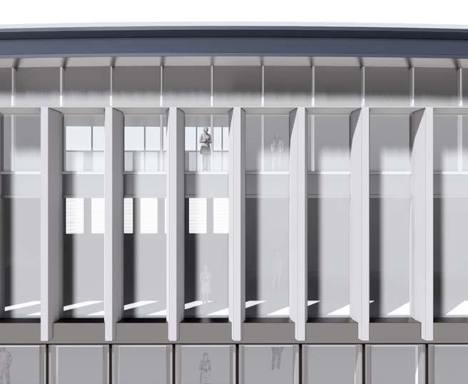
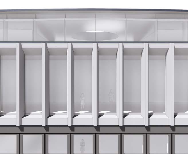
Variables such as the length, width, frequency and materiality of the vertical elements have been identified to mediate between the right level of openness to create a destination space and the right level of solidity to create ‘The Crown’ of the building.
Principles:
• Symmetry
• Read like a Crown
• Differentiation from level 27 Variables:
• Overall: Solidity & Openness
• Rhythm: Constant vs Gradient
• Materiality: Concrete vs other (metal)
• Elements: Width & Depth
Principles of the Crown
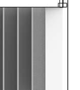
The approach taken was never to replace the crown of the building with something completely new and alien to the rest of the building, but to reinterpret the existing vertical elements. The first step taken was distributing a single vertical element along the perimeter, in varying
distances. A gradient approach would provide flexibility to control which areas would have more exposure to light and views. A constant rhythm follows the modulation of the facade and feel like a more natural addition.
Constant Gradient
Variable 2: Materiality
Two materials have been considered for the new fins: metal elements stand out clearly as a new addition, marrying with the materiality of the new window frames; concrete elements continue the massing of the building more clearly, moving away from a glass box approach.
Variable
Metal elements Concrete elements
1: Rhythm
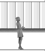
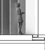
in order to achieve a maximum visibility from the inside and at the same time have a sense of solidity from the outside. Another important factor is how much do the fins project outwards from the facade line creating a greater sense of depth.

&
Projected 2200 1950 850 250 250 Internal External
&
2200 1950 1050 250 250 Internal External
& LONG Projected 2200 1800 1050 450 450 Internal External
&
2200 1800 850 450 450 Internal External
250
LONG
250
LONG Flush
600
600
SHORT Flush
The proportion of the elements, along with their repetition, will define how visible the restaurant would be from the outside. The crown would never be seen from a frontal view but always from a lower and angled perspective so we can play with the depth and width of these elements Variable 3: Depth & Width
Chosen Direction of Concrete Fin
A constant rhythm of concrete elements was selected as the preferred option following the studies. The principles for this option are as follows:
• Respecting the existing character and materiality.
• Constant regular rhythm.
• The elements follow the facade grid.
• Solid appearance from the outside.
• Maintaining exceptional views from the inside.
• Elements 450mm wide and 1m deep.
• Elements overshadow the glass facade.
• Glass line set in to create deeper reveals.
600 tapered & projected 2200 600 600 1000 1050 Internal External Glass Line Crown Proposal East West
Material Amendments to Planning Application
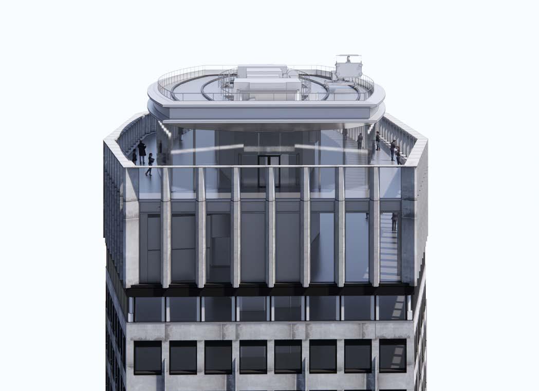
Change of levels to introduce external terrace

The design principle set for the consented scheme was to create a solid frame around the crown. However the vertical elements did not change, the top horizontal band had to be reduced in depth to reveal panoramic views from the terrace. Due to structural changes the lower band has been reduced as well with changed materiality to metal in order to create a consistent strong line around the building.
The driving factor for the adjustments to the Crown was to keep the top of the Crown at the same height as the consented scheme and the existing condition. This allows the proportions of the Crown to remain intact in relation to the rest of the building. As indicated in the adjacent diagram, by lowering level 29 the safety balustrade was created providing the opportunity to create external access to the emerged terrace. Presented change resulted in requirement to submit amendments to planning application because of the significant change to the facade and levels.
Stage 2 Stage 3
LEVEL 29 ACCESSIBLE EXTERNAL TERRACE INACCESSIBLE INFINITE EDGE ROOF LEVEL 28 MEZZANINE LEVEL 28 PARAPET LEVEL 5595 2040 150
Clear heights and levels


In order to reduce load on the existing perimeter columns all the plant equipment and BMU from level 29 were located on the roof. The largest machine is a 16 meters long and 3.5 meters high emergency power generator. The consented top of the building height sets the top limit of the generator location. The diagram below shows how the generator and the roof build up are pertruding into the restaurant reducing the clear height in the space between the cores.


2700 4500
Parapet 106.00 Roof Edge 109.90 Top of Building 111.05 Level 29 103.81 Level 28 98.52
Section
Short
3500 1040
Perspective Section
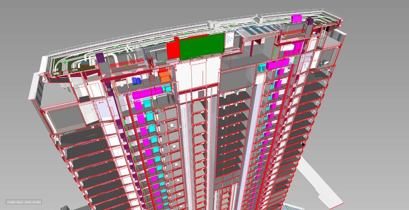
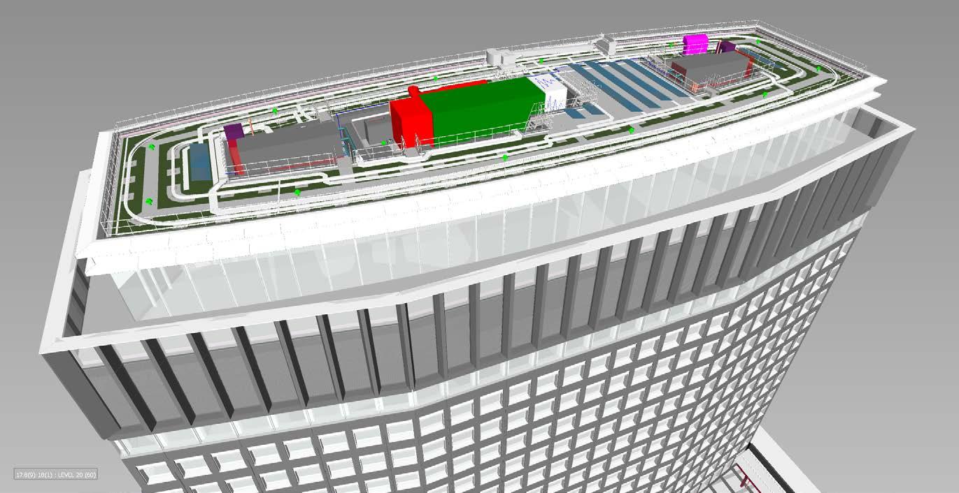
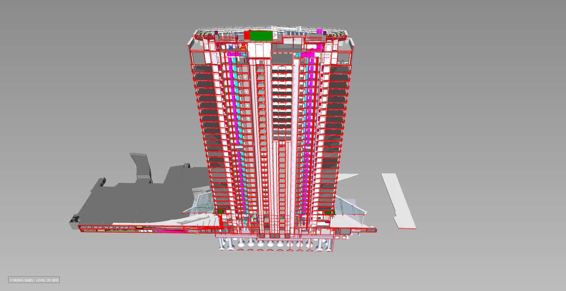
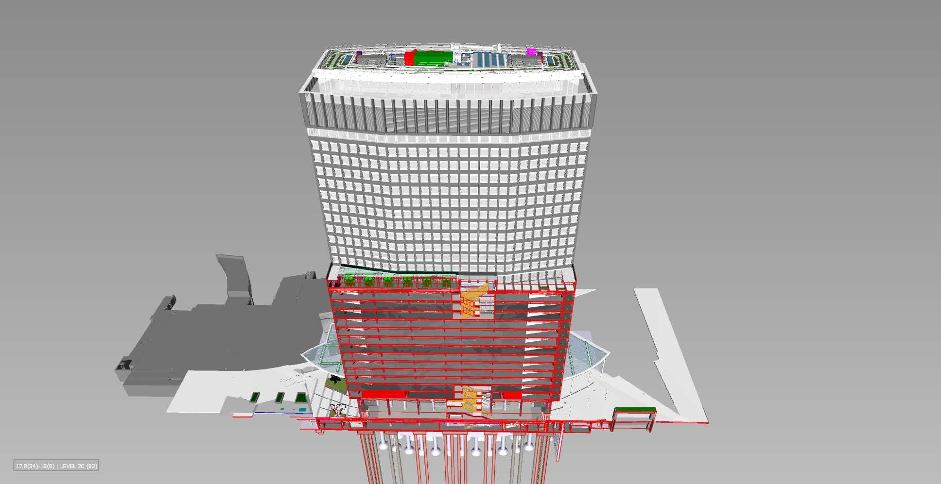
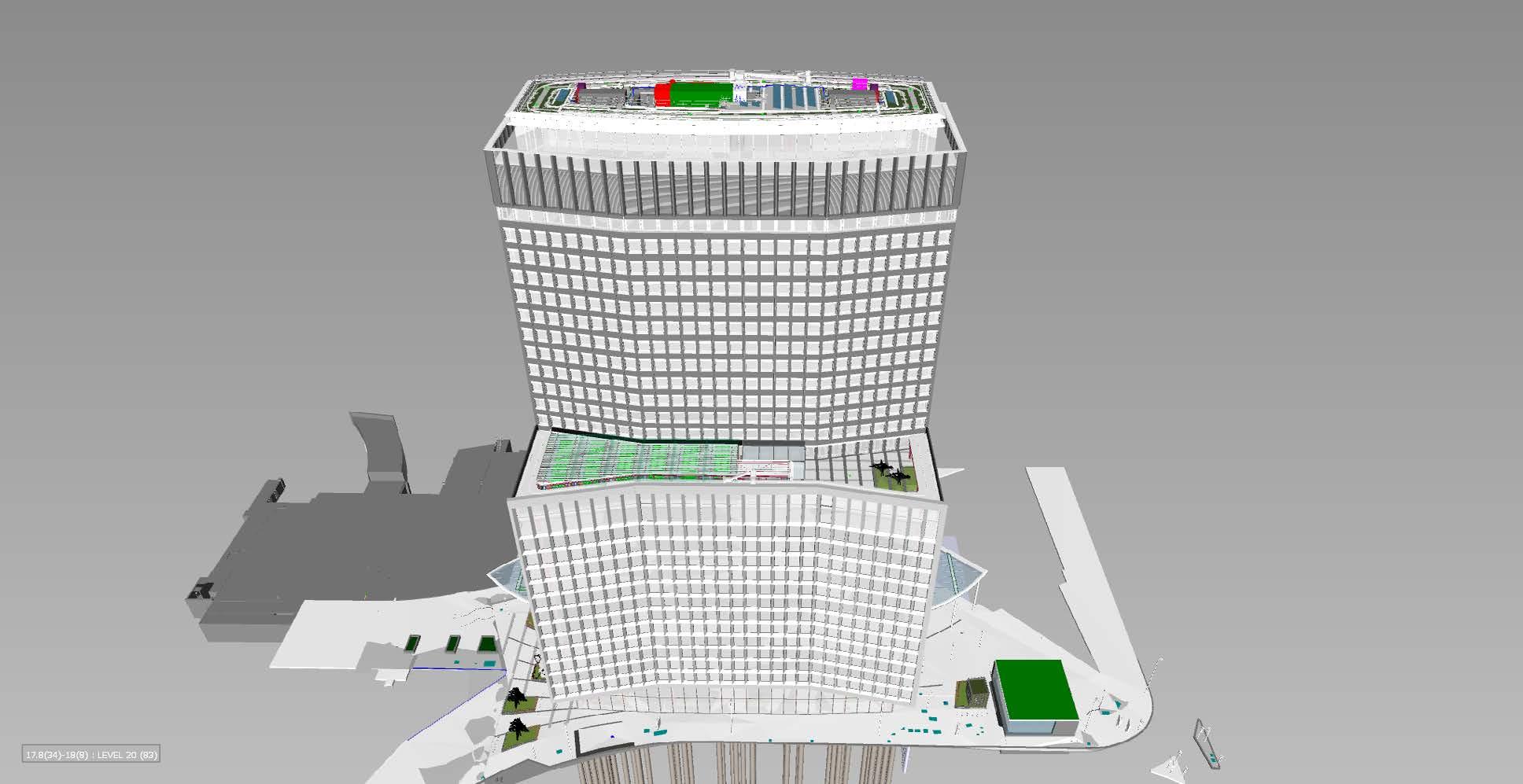
Clash Detection Tool
Coordination with other disciplines
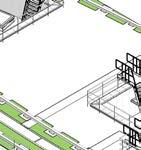
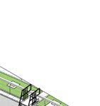
The total internal Gensler team consisted of 12 people. Including the consultants, the total team grew to around 30 professionals. There were 3 main Revit models to calibrate and coordinate: Mechanical and Electrical, Structural and Architectural. The image below is an example of how the team coordinated the design. Highlighted in red was my scope of the model and in green columns modelled by structural engineers. The image below shows clashes between Architectural and Structural models. By updating the facade panels, the clash was resolved. The crown apart from basement was the most complicated element of the building, not only from the structural and plant point of view but also because of the planning constraints in regards to the visual aspects of the facades, overlooking into Buckingham Palace gardens, consented views restrictions, Hyde Park light pollution from the rooftop bar and overall building height.

Section through rooftop
Perspective sections of the final model
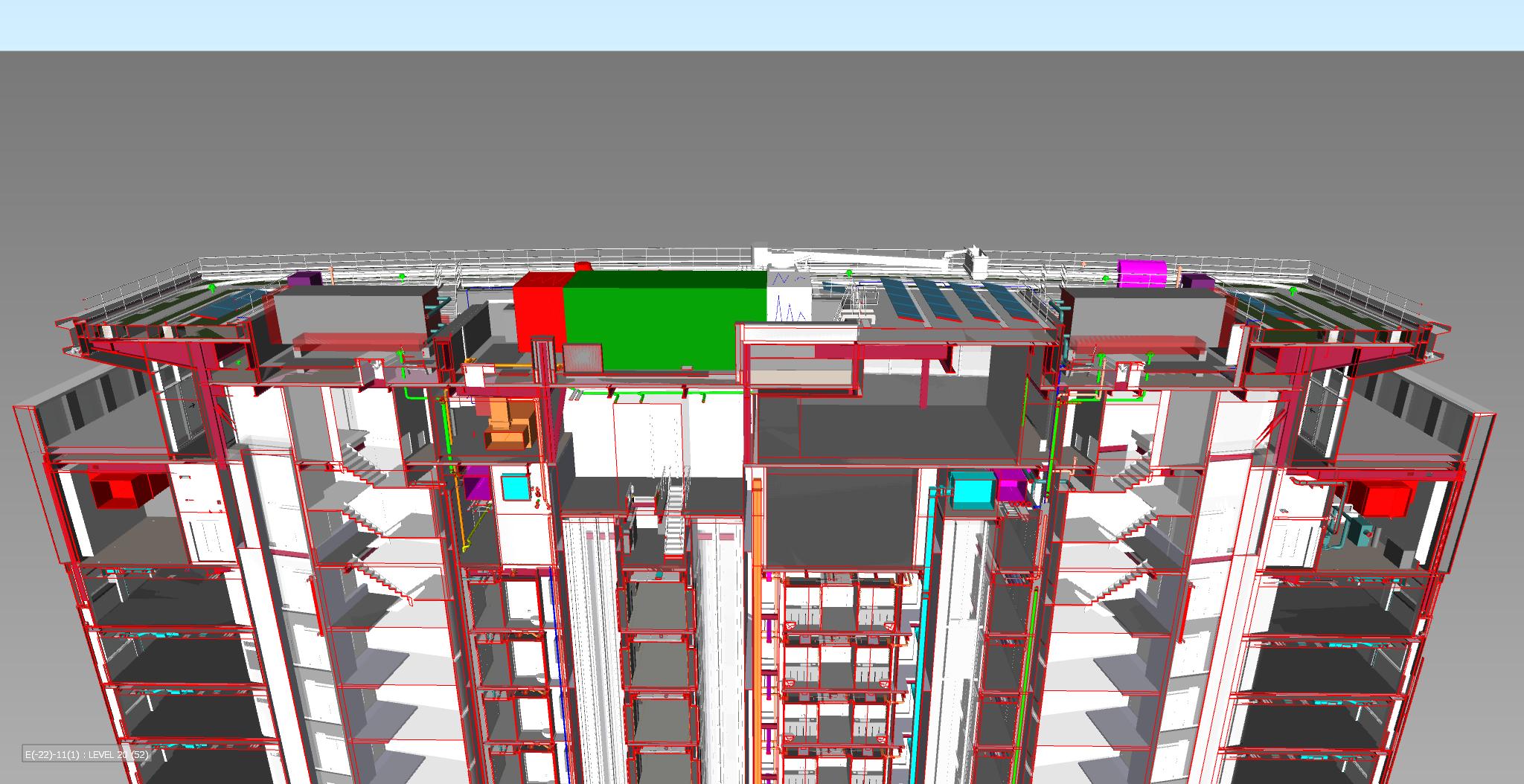
Section through the main core
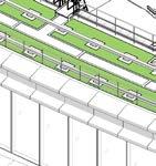
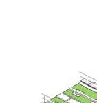
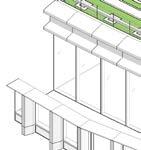
Final Crown Design Under Construction
Construction
Final Crown Design Under
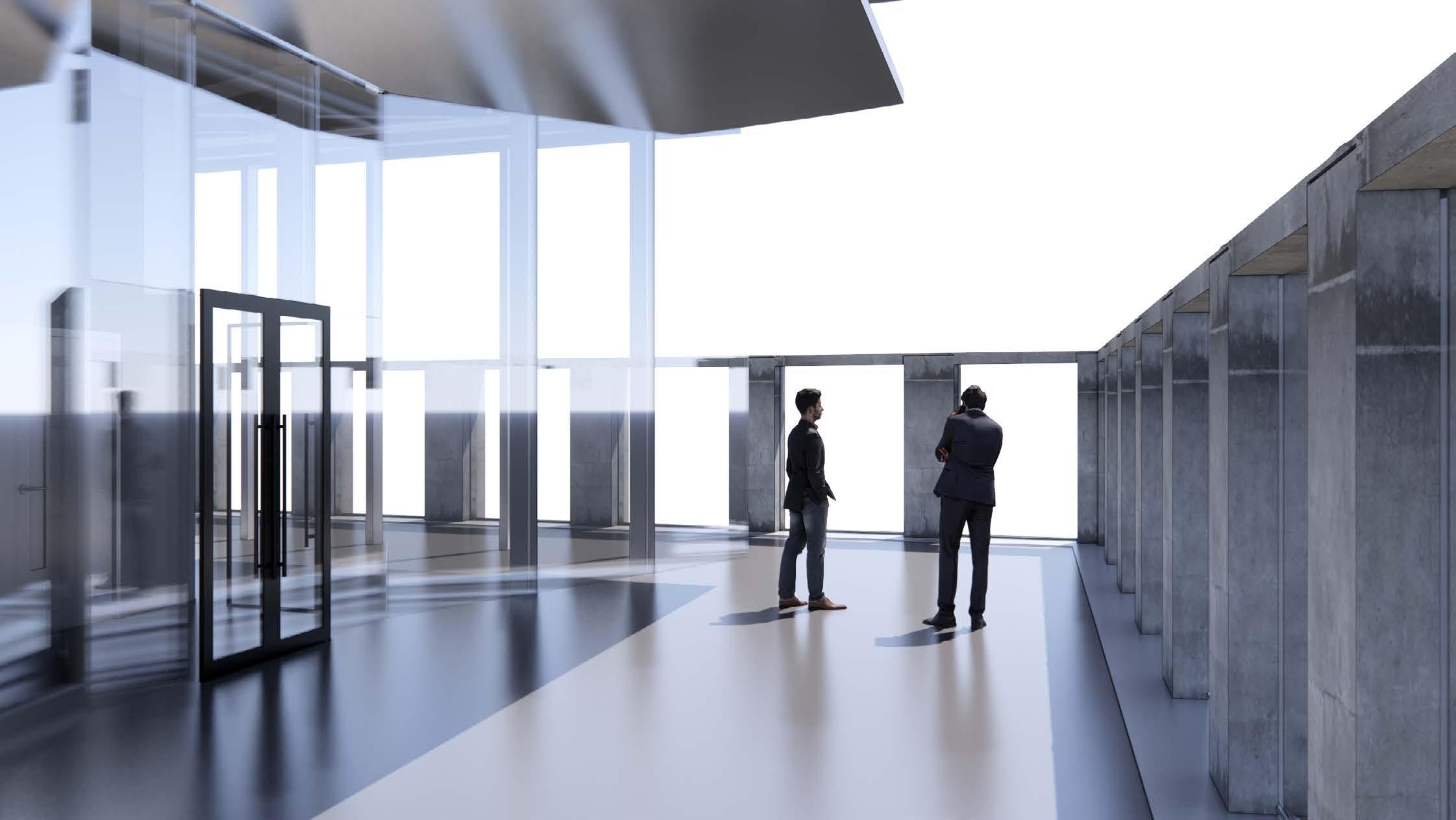
Level 29 - Terrace
Level 29 - Bar with 360 degrees viewing terrace

Level 28 - Restaurant
Final Crown Design Under Constructon
UP A-130002 01 02 A-140001 01 A-140002 01 A-140001 3 8 9 10 11 12 13 14 19 K H F 6 7 18 17 15 G J 16 5 FFL +95.140 4 E L 01 A-330050 A-130001 01 OFFICE 127-001 LIFT LOBBY 127-014 OFFICE 127-015 RISR 127-002 LIFT LOBBY 127-003 RISR 127-006 RISR 127-005 RISR 127-004 WC LOBBY 127-007 WC LOBBY 127-016 WC 127-019 RISR 127-021 RISR 127-022 LIFT LOBBY 127-020 RISR 127-023 RISR 127-025 RISR 127-026 LIFT LOBBY 127-024 RISR 127-027 127-003/1 127-002/1 127-003/2 127-004/1 127-007/1 127-007/2 127-027/1 127-024/1 127-024/2 127-026/1 127-022/1 127-020/1 127-020/2 127-021/1 127-007/4 127-020/4 127-016/1 127-016/2 127-015/1 127-014/1 127-014/2 STAIR 01 127-ST01 RISR 127-013 WC 127-012 WC 127-011 ACC. WC 127-010 WC 127-009 WC 127-008 STAIR 02 127-ST02 WC 127-018 WC 127-017 CLNRS 127-033 01 A-220007 127-020/3 127-020/5 127-020/6 127-020/7 127-007/3 127-007/5 127-007/6 WC 127-028 FGL-01 DPL-01 DPL-02 DPL-03 DPL-04 DPL-05 DPL-06 GL-01 FGL-02 CONDENSATE PIPE THROUGH EXISTING SLAB OPENING CONDENSATE PIPE THROUGH EXISTING SLAB OPENING SIM SIM SIM SIM SIM SIM SIM SIM A-230004 02 A-230004 01 A-230004 03 04 A-230004 04 A-230004 05 A-230004 05 A-230004 04 A-230004 04 A-230004 04 A-230004 04 A-230004 05 A-230004 05 A-230004 A-230004 02 A-230004 03 A-230004 01 SIM SIM SIM SIM SIM SIM SIM SIM 8 bays sp c g o w g ex ng ad b ow 12 bays Fins spacing following existing facade below b ys F ns sp n o o g g a de be ow 12bays @ 2210 26520 ays @2 0 1 680 8 s @22 176 01 A-420009 01 A-420010 A-130002 01 02 A-140001 01 A-140002 01 A-140001 3 8 9 10 11 12 13 14 19 K H F 6 7 18 17 15 G J 16 5 4 02 A-330050 OVERRUN OVERRUN OVERRUN E 8 bays sp c g o w g ex ng ad b ow 12 bays Fins spacing following existing facade below b ys F ns sp n o o g g a de be ow BROWNS KITCHEN EXTRACT L ACCESS HATCH ABOVE 8 bays Fins spacing following existing facade below 8 bays Fins spacing following existing facade below 128-002/4 128-008/1 128-004/1 128-015/1 128-016/1 128-018/1 128-017/1 128-002/2 128-014/1 128-013/1128-013/2 128-012/1 128-011/3 128-011/2 128-003/1 128-011/1 128-002/1 02 A-420009 02 A-420010 RISER RISER RISER ALIGN AL N ALIGN AL N ALIGN ALIGN AL N 150 STEP DOWN 150 STEP DOWN GLAZED FACADE LOUVRED FACADE ADJACENT TO PLANT GLAZED FACADE LIFE SAFETY MCC RM 128-015 STAIR 01 128-ST01 RISR 128-020 RISR 128-021 BOH CORR. 128-008 RISR 128-009 RISR 128-007 STAIR 02 128-ST02 LIFT LOBBY 128-004 RISR 128-005 LIFT LOBBY 128-018 RESTAURANT AND BAR 128-002 128-004/2 128-009/1 LIFT LOBBY 128-001 PLANT 128-016 PLANT 128-012 AHU 128-013 AHU 128-011 BOH CORR. 128-010 BOH CORR. 128-014 BOH CORR. 128-017 BOH CORR. 128-003 8 b F ns pa ng ow n e s fac e e w 12 bays Fins spacing following existing facade below b ys F ac g w ng e s ng aca w 128-022/1 128-002/3 128-002/5 RISR 128-023 128-021/1 128-005/1 RISR 128-027 128-013/3 128-013/4 128-013/5 128-013/6 128-011/4 128-011/5 128-011/6 128-011/7 LOUVRED FACADE OUVRED FAC DE LOUVRED FACADE LOUVRED FACADE LOUVRED FACADE 02 A-220007 ALSO TO BE READ IN CONJUNCTION WITH: 1) A-070000 SERIES DRAWING'S FOR ALL WALL TYPE & WINDPOST CODES FLOOR BUILDUP TRANSITION. REFER TO FLOOR DETAILS SERIES A-500000 SETTING OUT OF MEP SERVICES ON RCP's AND GA'S SUBJECT TO DETAIL DESIGN DEVELOPMENT FLOOR BOXES TO BE SET OF TO CENTER OF FULL TILE. REFER TO FINISHES PLANS FOR SETTING OUT OF TILES. ALL VISIBLE SERVICE OUTLETS LOCATIONS TO BE AGREED WITH THE ARCHITECT SHEET NOTES Gensler All rights reserved, including but not limited to he Copyright, Design and Patents Act 1988 date revision note drawn checked rev P N key plan category project client project code date first issue scale family project number GENERAL NOTES 1. DO NOT SCALE FROM DRAWINGS. ALL DISCREPANCIES TO BE REPORTED TO GENSLER ARCHITECT IMMEDIATELY. 2. ALL EXISTING BUILDING DIMENSIONS TO BE VERIFIED ON SITE PRIOR TO COMMENCEMENT OF CONSTRUCTION 3. ALL DRAWINGS TO BE READ IN CONJUNCTION WITH GRAPHIC SYMBOLS DOCUMENT 0885_001-GEN-XXX-XXX-DR-A-000002 4. ALL DRAWINGS TO BE READ IN CONJUCTION WITH STRUCTURAL AND MEP ENINGEER’S INFORMATION 5. PLEASE REFER TO 0885_001-GEN-XXX-XXX-SP-A-900100 FOR SPECIFICATION 6. PLEASE REFER TO 0885_001-GEN-XXX-XXX--SH-A-86000 FOR FINISHES SCHEDULE 7. PLEASE REFER TO 0885_001-GEN-XXX-XXX--SH-L-86000 FOR LANDSCAPE FINISHES 8. PLEASE REFER TO 0885_001-GEN-XXX-XXX--SH-A-84000 FOR SANITARYWARE SCHEDULE 9. PLEASE REFER TO 0885_001-GEN-XXX-XXX--SH-A-85000 FOR FF AND E SCHEDULE lead consultant title origin vol/systype rolenumber rev lvl/loc drawnchecked status Tel +44 (0) 20 7073 9600 Fax +44 (0) 20 7539 1917 Thomas More Square London, LND E1W 1YW England United Kingdom LAND SECURITIES PROPERTIES 100 VICTORIA STREET LONDON, UK SW1E 5JL As indicated@A0 P10 26/01/2021 11:23:54 0885_001 GA PLAN LEVEL 27-28 008.7638.000 PORTLAND HOUSE WESTMINSTER, LONDON, SW1E 5RS 1 GENERAL ARRANGEMENT 110000-119999 PLANS SETTING OUT 31.01.2019 FOS RK GEN XXX A-113700 127 DR S4 2020 PREVIOUS DRAWING NUMBER: PH-GEN-XX-27-DR-A-113700 SCALE: 100 GA PLAN -LEVEL 27 01 SCALE: 100 GA PLAN -LEVEL 28 02 P0131.01.2020STAGE 3 DESIGN FREEZEMdOSC P0213.03.2020STAGE 3 100% SUBMISSIONMdOBF P0307.05.2020STAGE 3 100% SUBMISSIONRSCK P0429.05.2020STAGE 3 100% RE-SUBMISSIONJVBF P0522.06.2020STAGE 3 CLOSE OUTGLDW P0605.10.2020MID STAGE FREEZERKDW P0709.11.2020STAGE 4 BACKGROUND FREEZE RKDW P0818.11.2020FOR COORDINATIONRKDW P0910.12.2020FOR COORDINATIONRKDW P1026.01.2021STAGE 4A SUBMISSIONRKDW Sample of Technical Documentation Plans of the Crown - Restaurant level 28 and office level 27
Sample of Technical Documentation Plans of level 29 Bar and level 28 Mezzanine
SCALE: 100 GA PLAN -LEVEL 28M 01
BOH-03 (Chemical Resistant Plant Rooms)
FLOOR SKIRTING WALL CEILING
FA-02 FA-02 Cove Skirting to 100mm height PT-03 (to 3m height, CO-01 above) PT-26
BOH-04 (Plant Rooms with waterproofing requirements FLOOR SKIRTING WALL CEILING
PT-12 PT-12 UP TO 600MM CO-01 PT-26
BOH-05 (UKPN Access -Ground Floor) FLOOR SKIRTING WALL CEILING
FA-01 FA-01, Cove Skirting to 100mm height PT-02 PT-25, painted with PT-04 BOH-06 (Retail) FLOOR SKIRTING WALL CEILING
N/A (By tenant) N/A (By tenant) PT-02 on partitions CO-01 on existing core walls N/A (By tenant)
BOH-07 (BOH Lift Lobbies, Storage Rooms above basement) FLOOR SKIRTING WALL CEILING
BOH-08 (New Stair Cores)
FLOOR SKIRTING WALL WALL PROTECTION CEILING
FA-01 FA-01 Cove Skirting H:100mm PT-02 full-height PT-25, painted with PT-04
FA-06, Stair Nosings FA-07 FA-06 Cove Skirting to 100mm height, RAL 7021 PT-02 full-height New UPVC railings, to match existing stair finish PT-15 to stair soffits, to match existing stair finish BOH-09 (Cleaners Closet)
FLOOR SKIRTING WALL CEILING
BOH-10 (BOH with access floor requirements)
WALL PROTECTION CEILING
TL-01 SK-04 PT-02, TL-03 to mop sink wall full height PT-26 TEN-01 FLOOR SKIRTING WALL CEILING
FA-06 treads and risers, FA-07 nosings FA-06 Cove Skirting to 100mm height, RAL 7021 PT-02 full-height Existing UPVC railings, metal to match wall PT-02 PT-26
AP-01, finish by tenant SK-02 (existing & new core wall, interior partitions) PT-25 to existing core walls, painted with PT-06 PT-06 to new core walls CL-01 in office areas, CL-03 to existing perimeter
PT-16 (Fire Protective Spray) To be applied all existing basement soffits where indicated by dashed line extent in conjunction with ceiling finish noted
0885_001-GEN-XXX-XXX--SH-A-86000 drawnchecked status
0885_001-GEN-XXX-XXX--SH-A-84000 GA PLAN LEVEL 28M-29 008.7638.000
0885_001-GEN-XXX-XXX--SH-A-85000 PORTLAND HOUSE WESTMINSTER, LONDON, SW1E 5RS
P0909.11.2020STAGE 4 BACKGROUND FREEZE RKDW P1010.12.2020FOR COORDINATIONRKDW P1126.01.2021STAGE 4A SUBMISSIONKKDW
SCALE: 100 GA PLAN -LEVEL 29 02 P0104.10.2019ISSUED FOR INFORMATIONMdOSC P0218.10.2019STAGE 3 50% SUBMISSIONMdOSC P0331.01.2020STAGE 3 DESIGN FREEZEAHSC P0413.03.2020STAGE 3 100% SUBMISSIONAHBF P0507.05.2020STAGE 3 100% SUBMISSIONRSCK P0629.05.2020STAGE 3 100% RE-SUBMISSIONJVBF P0722.06.2020STAGE 3 CLOSE OUTGLDW P0805.10.2020MID STAGE FREEZEKKDW
1 GENERAL ARRANGEMENT 110000-119999 PLANS SETTING OUT 04.10.2019
AP-04 N/A PT-02 to 3m height, CO-01 above PT-26 CARPARKING COLUMNS TYPE A TYPE B PT-08 to all sides PT-10 to all sides rev lvl/loc
FOS KK GEN XXX A-113800 128 DR
0885_001-GEN-XXX-XXX--SH-L-86000 Tel +44 (0) 20 7073 9600 Fax +44 (0) 20 7539 1917 Thomas More Square London, LND E1W 1YW England United Kingdom LAND SECURITIES PROPERTIES 100 VICTORIA STREET LONDON, UK SW1E 5JL As indicated@A0 P11 26/01/2021 11:24:34 0885_001
S4 2020 PREVIOUS DRAWING NUMBER: PH-GEN-XX-28-DR-A-113800
02 A-330050 03 A-330050 A-130002 01 02 A-140001 01 A-140002 01 A-140001 3 8 9 10 11 12 13 14 19 K H F 6 7 18 17 15 G J 16 5 4 E 8 bays sp c g o w g ex ng ad b ow 12 bays Fins spacing following existing facade below b ys F ns sp n o o g g a de be ow PLANT BELOW PLANT BELOW AHU BELOW AHU BELOW RESTAURANT AND BAR BELOW LIFT LOBBY BELOW L ACCESS HATCH 8 bays Fins spacing following existing facade below 8 bays Fins spacing following existing facade below OVERRUN OVERRUN OVERRUN OVERRUN RISER RISER RISER RISER RISER ST-01 ST-02 RISER LIFT MOTOR ROOM 128-100 8 b F ns pa ng ow n e s fac e e w 12 bays Fins spacing following existing facade below b ys F ac g w ng e s ng aca w A-130003 07 RISERRISER RISER RISER LIFT LOBBY BELOW LIFT LOBBY BELOW LOUVRED FACADE OUVRED FAC DE LOUVRED FACADE LOUVRED FACADE LOUVRED FACADE 03 A-420009 03 A-420010 01 A-220008 BACK-OF HOUSE FINISHES LEGEND BOH-01 (BOH corridors w protection) FLOOR SKIRTING WALL WALL PROTECTION CEILING FA-01 FA-01 Cove Skirting to 100mm height PT-02 (to 3m height, CO-01 above) PR-02 (400mm and 1000mm height) PT-26
(General Plant Rooms & Electrical Plant Rooms) FLOOR SKIRTING WALL CEILING FA-01 FA-01 Cove Skirting to 100mm height PT-02 (to 3m height, CO-01 above) PT-26
(Existing Stair Cores) FLOOR SKIRTING WALL
BOH-02
BOH-11
02 A-140001 01 A-140002 01 A-140001 3 11 19 H OVERRUN TERRACE 129-015 01 A-330051 OVERRUN OVERRUN OVERRUN LMR BELOW PAVILION ROOF OUTLINE FFL +103.810 E 8 ba sp c o w g ex ng ad b ow 12 bays Fins spacing following existing facade below b ys F ns sp n o o g g a de be ow 7.5 14.5 8.5 6.5 5.5 4.5 13.5 12.5 15.5 16.5 17.5 L 8 bays Fins spacing following existing facade below 8 bays Fins spacing following existing facade below FFL +103.510 04 A-420009 04 A-420010 129-011/1 129-014/3 129-002/2 129-006/1 P1 METAL STAIR TO THE ROOF ACCESS HATCH ABOVE 01 A-330051 STAIR 01 129-ST01 RISR 129-004 RISR 129-009 BROWNS EXTRACT PLANT 129-010 STAIR 02 129-ST02 FIRE ESC. LOBBY 129-011 RISR 129-013 FIRE ESC. LOBBY 129-003 RESTAURANT AND BAR 129-001 WC EXTRACT 129-007 RISR 129-012 RISR 129-005 P1A P1G P3A P E P3A P3 P3D P3C P3 P1E P3A P3A P3D P A P3D P3C P D PT-06 L1B L1B 8 b F ns pa ng ow n s fac e e w 12 bays Fins spacing following existing facade below b F ac g w ng e s ng aca w FOR GRID SETTING OUT REFER TO STRUCTURAL ENGINEER. FOR LOADING PLAN REFER TO STRUCTURAL ENGINEER. 129-003/1 29-002/1 29-001/1 129-010/1 129-006/2 129-006/3 FIRE ESC. LOBBY 129-006 29-001/2 29-014/1 734 905 150 AP AP RWL +103.64 RWL +103.63 FLAT ROOF RWL +103.64 FLAT ROOF RWL +103.62 RAINWATER OUTLET RF-02 FALL 1/80 RF-02 FFL +103.810 FFL +103.810 FFL +103.810 RF-02 RF-02 RF-02 SOP FULL TILE FROM FACE OF FACADE SOP FULL TILE FROM FACE OF FACADE LIFT LOBBY BELOW AP AP AP AP AP AP 02 A-220008 ALSO TO BE READ IN CONJUNCTION WITH: 1) -070000 SERIES DRAWING'S FOR ALL WALL TYPE WINDPOST CODES FLOOR BUILDUP TRANSITION. REFER TO FLOOR DETAILS SERIES -500000 SETTING OUT OF MEP SERVICES ON RCP's AND GA'S SUBJECT TO DETAIL DESIGN DEVELOPMENT FLOOR BOXES TO BE SET OF TO CENTER OF FULL TILE. REFE TO FINISHES PLANS FOR SETTING OUT OF TILES. ALL VISIBLE SERVICE OUTLETS LOCATIONS TO BE AGREED WIT THE ARCHITECT SHEET NOTES Gensler All rights reserved, including but not limited to he Copyright, Design and Patents Act 1988 date revision note drawn checked P N key plan category project client project code date first issue scale family project number GENERAL NOTES 1. DO NOT SCALE FROM DRAWINGS. ALL DISCREPANCIES TO BE REPORTED TO GENSLER ARCHITECT IMMEDIATELY. 2. ALL EXISTING BUILDING DIMENSIONS TO BE VERIFIED ON SITE PRIOR TO COMMENCEMENT OF CONSTRUCTION 3. ALL DRAWINGS TO BE READ IN CONJUNCTION WITH GRAPHIC SYMBOLS DOCUMENT 0885_001-GEN-XXX-XXX-DR-A-000002 4. ALL DRAWINGS TO BE READ IN CONJUCTION WITH STRUCTURAL AND MEP ENINGEER’S INFORMATION 5. PLEASE REFER TO 0885_001-GEN-XXX-XXX-SP-A-900100 FOR SPECIFICATION 6. PLEASE REFER TO
FOR FINISHES SCHEDULE 7. PLEASE REFER TO
FOR LANDSCAPE FINISHES 8. PLEASE REFER TO
FOR SANITARYWARE SCHEDULE 9. PLEASE REFER TO
FLOOR SKIRTING WALL CEILING FOR FF AND E SCHEDULE lead consultant title origin vol/systype rolenumber
BOH-03 (Chemical Resistant Plant Rooms) FLOOR SKIRTING WALL CEILING
(By tenant) PT-02 on partitions CO-01 on existing core walls N/A (By tenant)
BOH-07 (BOH Lift Lobbies, Storage Rooms above basement) FLOOR SKIRTING WALL CEILING
FA-01 FA-01 Cove Skirting H:100mm PT-02 full-height PT-25, painted with PT-04
BOH-08 (New Stair Cores)
FLOOR SKIRTING WALL WALL PROTECTION CEILING
FA-06, Stair Nosings FA-07 FA-06 Cove Skirting 100mm height, RAL 7021 PT-02 full-height New UPVC railings, to match existing stair finish PT-15 to stair soffits, to match existing stair finish BOH-09 (Cleaners Closet)
FLOOR SKIRTING WALL CEILING
BOH-10 (BOH with access floor requirements) FLOOR SKIRTING WALL CEILING
AP-04 N/A PT-02 to 3m height, CO-01 above PT-26
TL-01 SK-04 PT-02, TL-03 to mop sink wall full height PT-26 TEN-01 FLOOR SKIRTING WALL CEILING
AP-01, finish by tenant SK-02 (existing new core wall, interior partition PT-25 to existing core walls, painted with PT-06 PT-06 to new core walls CL-01 in office areas, CL-03 to existing perimeter
CARPARKING COLUMNS TYPE A TYPE B PT-08 to all sides PT-10 to all sides
FA-02 FA-02 Cove Skirting 100mm height PT-03 (to 3m height, CO-01 above) PT-26 PT-16 (Fire Protective Spray) To be applied to all existing basement soffits where indicated by dashed line extent in conjunction with ceiling finish noted
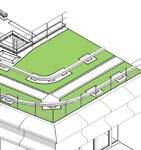
850 02 A-140001 01 A-140002 01 A-140001 3 11 19 H GENERATOR ROOF EDGE TENANT 24H TENANT 24H TERRACE BELOW PAVILION GLAZING OUTLINE BELOW SILENCER ATTN ATTN E 7.5 14.5 PV PANELS 8.5 6.5 5.5 4.5 13.5 12.5 15.5 16.5 17.5 L GREEN ROOF GREEN ROOF WALKWAY GR D E T NG OU S P R STRU T RAL ENG N E S DR W N R E T NG OU S P R T UCTURA ENG N E S DR W NG 5 5 GUTTER UNDER PAVERS ACCESS HATCH TO EGRESS STAIR EXTENSIVE SEDUM GREEN ROOF SYSTEM FOR GRID SETTING OUT REFER TO STRUCTURAL ENGINEER. FOR LOADING PLAN REFER TO STRUCTURAL ENGINEER. AUTOMATIC OPENING VENTILATOR 01 AUTOMATIC OPENING VENTILATOR 02 PV PANELS RWL +109.400 PV PANELS PV PANELS PV PANELS RAINWATER OUTLET RAINWATER OUTLET RAINWATER OUTLET RAINWATER OUTLET RAINWATER OUTLET RAINWATER OUTLET RAINWATER OUTLET RAINWATER OUTLET RAINWATER OUTLET RAINWATER OUTLET RAINWATER OUTLET RAINWATER OUTLET SHIP STAIR 01 SHIP STAIR 02 SHIP STAIR 03 SHIP STAIR 04 SHIP STAIR 05 SHIP STAIR 08 SHIP STAIR 07 SHIP STAIR 06 BMU TRACKS TERRACE BELOW PAVILION GLAZING OUTLINE BELOW FRL +109.55 FRL +107.81 FRL +107.55 FRL +107.81 FRL +109.55 FRL +109.55 FRL +109.55 FRL +109.55 FRL +109.55 WALKWAY FALL 1/80 GUTTER GUTTER UNDER PAVERS FALL 1/80 FALL 1/80 FALL 1/80 FALL 1/80 FALL 1/80 FALL 1/80 FALL 1/80 FALL 1/80 FALL 1/80 FALL 1/80 FALL 1/80 RF-01 RF-01 RF-01 RF-01 RF-01 RF-01 RF-01 RF-01 RF-01 BALAST NOT LAID TO FALL BALAST NOT LAID TO FALL EXTENSIVE SEDUM GREEN ROOF SYSTEM CONCRETE PAVERS BALAST NOT LAID TO FALL CONCRETE PAVERS RWL +109.400 RWL +109.400 RWL +109.400 RWL +109.400 RWL +109.40 RWL +109.37 RWL +109.30 RWL +109.40 RWL +109.37 RWL +109.30 RWL +109.40 RWL +109.37 RWL +109.33 RWL +109.39 RWL +109.40 RWL +109.37 RWL +109.33 RWL +109.39 UPSTAND FOR GENERATOR UPSTAND FOR TENANT 24 UPSTAND FOR TENANT 24 RF-03 RF-03 RF-03 RF-03 RF-03 RF-03 RF-03 RF-03 RF-03 RF-03 RF-03 RF-03 RF-03 RF-03 RF-03 BACK-OF HOUSE FINISHES LEGEND BOH-01 (BOH corridors protection) FLOOR SKIRTING WALL WALL PROTECTION CEILING FA-01 FA-01 Cove Skirting 100mm height PT-02 (to 3m height, CO-01 above) PR-02 (400mm and 1000mm height) PT-26 BOH-02 (General Plant Rooms & Electrical Plant Rooms) FLOOR SKIRTING WALL CEILING FA-01 FA-01 Cove Skirting 100mm height PT-02 (to 3m height, CO-01 above) PT-26 BOH-11 (Existing Stair Cores) FLOOR SKIRTING WALL WALL PROTECTION CEILING FA-06 treads and risers, FA-07 nosings FA-06 Cove Skirting 100mm height, RAL 7021 PT-02 full-height Existing UPVC railings,
requirements FLOOR
metal to match wall PT-02 PT-26 BOH-04 (Plant Rooms with waterproofing
SKIRTING WALL CEILING PT-12 PT-12 UP TO 600MM CO-01 PT-26 BOH-05 (UKPN Access -Ground Floor) FLOOR SKIRTING WALL CEILING FA-01 FA-01, Cove Skirting to 100mm height PT-02 PT-25, painted with PT-04 BOH-06 (Retail) FLOOR SKIRTING WALL CEILING N/A (By tenant) N/A
02 A-140001 01 A-140002 01 A-140001 3 11 19 K H F E 7.5 14.5 8.5 6.5 5.5 4.5 13.5 12.5 15.5 16.5 17.5 L GENERATOR TENANT 24H TENANT 24H ATTN ATTN FALL 1/80 FALL 1/80 FRL +107.81 FRL +107.81 ACCESS HATCH TO EGRESS STAIR AUTOMATIC OPENING VENTILATOR 01 AUTOMATIC OPENING VENTILATOR 02 UPSTAND FOR GENERATOR UPSTAND FOR TENANT 24 UPSTAND FOR TENANT 24 RWL +107.64 RWL +107.62 RWL +107.62 RWL +107.65 RWL +107.62 RWL +107.34 RWL +107.34 RWL +107.35 RWL +107.60 RWL +107.60 RWL +107.59 RWL +107.59 FRL +107.55 RWL +107.55 RWL +107.65 RWL +107.35 RWL +107.35 RWL +107.35 RWL +107.35 RWL +107.35 RWL +107.38 RWL +107.38 RWL +107.38 RWL +107.40 RWL +107.37 RWL +107.65 RWL +107.62 RAINWATER OUTLET BALAST CONCRETE PAVERS RF-01 RF-01 RF-01 RF-01 RF-01 RF-01 RF-01 RF-01 RF-01 ALSO TO BE READ IN CONJUNCTION WITH: -070000 SERIES DRAWING'S FOR ALL WALL TYPE WINDPOST CODES FLOOR BUILDUP TRANSITION. REFER TO FLOOR DETAILS SERIES -500000 SETTING OUT OF MEP SERVICES ON RCP's AND GA'S SUBJECT TO DESIGN DEVELOPMENT FLOOR BOXES TO BE SET OF TO CENTER OF FULL TILE. REFE TO FINISHES PLANS FOR SETTING OUT OF TILES. ALL VISIBLE SERVICE OUTLETS LOCATIONS TO BE AGREED WIT THE ARCHITECT SHEET NOTES Gensler All rights reserved, including but not limited to he Copyright, Design and Patents Act 1988 date revision note drawn checked P N key plan category project client project code date first issue scale family project number GENERAL NOTES 1. DO NOT SCALE FROM DRAWINGS. ALL DISCREPANCIES TO BE REPORTED TO GENSLER ARCHITECT IMMEDIATELY. 2. ALL EXISTING BUILDING DIMENSIONS TO BE VERIFIED ON SITE PRIOR TO COMMENCEMENT OF CONSTRUCTION 3. ALL DRAWINGS TO BE READ IN CONJUNCTION WITH GRAPHIC SYMBOLS DOCUMENT 0885_001-GEN-XXX-XXX-DR-A-000002 4. ALL DRAWINGS TO BE READ IN CONJUCTION WITH STRUCTURAL AND MEP ENINGEER’S INFORMATION 5. PLEASE REFER TO 0885_001-GEN-XXX-XXX-SP-A-900100 FOR SPECIFICATION 6. PLEASE REFER TO 0885_001-GEN-XXX-XXX--SH-A-86000 FOR FINISHES SCHEDULE 7. PLEASE REFER TO 0885_001-GEN-XXX-XXX--SH-L-86000 FOR LANDSCAPE FINISHES 8. PLEASE REFER TO
FOR SANITARYWARE SCHEDULE 9. PLEASE REFER TO
FOR FF AND E SCHEDULE lead consultant title origin vol/systype rolenumber rev lvl/loc drawnchecked status Tel +44 (0) 20 7073 9600 Fax +44 (0) 20 7539 1917 Thomas More Square London, LND E1W 1YW England United Kingdom LAND SECURITIES PROPERTIES 100 VICTORIA STREET LONDON, UK SW1E 5JL As indicated@A0 P09 26/01/2021 11:25:15 0885_001 GA PLAN LEVEL 30 AND ROOF 008.7638.000 PORTLAND HOUSE WESTMINSTER, LONDON, SW1E 5RS 1 GENERAL ARRANGEMENT 110000-119999 PLANS SETTING OUT 31.10.2019 FOS KK GEN XXX A-114000 130 DR S4 2020 PREVIOUS DRAWING NUMBER: PH-GEN-XX-29-DR-A-113900 SCALE: 100 GA PLAN -ROOF 02 SCALE: 100 GA PLAN -LEVEL 30 01 P0131.01.2020STAGE 3 DESIGN FREEZEAHSC P0213.03.2020STAGE 3 100% SUBMISSIONAHBF P0307.05.2020STAGE 3 100% SUBMISSIONRSCK P0429.05.2020STAGE 3 100% RE-SUBMISSIONJVBF P0522.06.2020STAGE 3 CLOSE OUTGLDW P0605.10.2020MID STAGE FREEZEKKDW P0709.11.2020STAGE 4 BACKGROUND FREEZE RKDW P0810.12.2020FOR COORDINATIONRKDW P0926.01.2021STAGE 4A SUBMISSIONKKDW
Technical
Roof
0885_001-GEN-XXX-XXX--SH-A-84000
0885_001-GEN-XXX-XXX--SH-A-85000
Sample of
Documentation
Plans


11 H 15 7.5 14.5 8.5 9.5 6.5 5.5 13.5 12.5 15.5 16.5 A-330052 02 05 A-330052 60 0 0 0 00 00 0 0 0 0 1 38 510 600 600 200 200 600 600 200 600 600 641 600 638 451 00 FACADE SETTING OUT FROM THE CENTRE LINE 600 600 600 600 600 FACADE SETTING OUT FROM THE CENTRE LINE 600 600 600 600 600 600 600 600 FACADE SETTING OUT FROM THE CENTRE LINE FACADE SETTING OUT FROM THE CENTRE LINE 600 600 600 593 593 600 629 600 200 550 600 0 6 6 60 600 00 00 0 0 6 6 600 600 600 600 600 600 600 600 600 900 310 600 600 200 200 600 600 259 FACADE SETTING OUT FROM THE CENTRE OF THE WALL 549 600 600 200 40 600 600 600 600 600 600 600 580 683 427 81 0 0 00 00 60 60 6 6 0 5 607 5 392 47 631 690 0 6 6 60 60 4 8 6 60 0 0 0 00 0 0 0 0 51 556 600 600 200 600 600 600 600 600 600 600 580 FACADE SETTING OUT FROM THE CENTRE LINE 600 600 600 600 600 600 600 600 FACADE SETTING OUT FROM THE CENTRE LINE 629 600 200 600 00 60 60 6 6 0 0 00 00 60 60 600 600 600 600 600 476 5 00 00 0 6 6 60 60 600 00 607 5 392 4 6 630 631 727 FACADE SETTING OUT FROM THE CENTRE OF THE WALL FACADE SETTING OUT FROM THE CENTRE OF THE WALL FACADE SETTING OUT FROM THE CENTRE OF THE WALL FACADE SETTING OUT FROM THE CENTRE OF THE WALL FACADE SETTING OUT FROM THE CENTRE OF THE WALL 03 A-330052 04 A-330052 SF-001601 SF-001602 3240 1710 TOB FFL+111.05 LEVEL 30R FFL+109.55 H LEVEL 30 FFL+107.81 2150 MT-83 MT-83 1&2 SF-001600 TOB FFL+111.05 LEVEL 30R FFL+109.55 LEVEL 30 FFL+107.81 MT-83 MT-83 MT-83 MT-83 MT-83 MT-83 MT-83 MT-83 MT-83 3&4 SF-001600 BALUSTRADE POSTS @1200 DISTANCE TOB FFL+111.05 LEVEL 30R FFL+109.55 H LEVEL 30 FFL+107.81 MT-83 TOB FFL+111.05 LEVEL 30R FFL+109.55 H LEVEL 30 FFL+107.81 MT-83 Gensler All rights reserved, including but not limited to he Copyright, Design and Patents Act 1988 date revision note drawn checked rev P N key plan category project client project code date first issue scale family project number GENERAL NOTES 1. DO NOT SCALE FROM DRAWINGS. ALL DISCREPANCIES TO BE REPORTED TO GENSLER ARCHITECT IMMEDIATELY. 2. ALL EXISTING BUILDING DIMENSIONS TO BE VERIFIED ON SITE PRIOR TO COMMENCEMENT OF CONSTRUCTION 3. ALL DRAWINGS TO BE READ IN CONJUNCTION WITH GRAPHIC SYMBOLS DOCUMENT 0885_001-GEN-XXX-XXX-DR-A-000002 4. ALL DRAWINGS TO BE READ IN CONJUCTION WITH STRUCTURAL AND MEP ENINGEER’S INFORMATION 5. PLEASE REFER TO 0885_001-GEN-XXX-XXX-SP-A-900100 FOR SPECIFICATION 6. PLEASE REFER TO 0885_001-GEN-XXX-XXX--SH-A-86000 FOR FINISHES SCHEDULE 7. PLEASE REFER TO 0885_001-GEN-XXX-XXX--SH-L-86000 FOR LANDSCAPE FINISHES 8. PLEASE REFER TO 0885_001-GEN-XXX-XXX--SH-A-84000 FOR SANITARYWARE SCHEDULE 9. PLEASE REFER TO 0885_001-GEN-XXX-XXX--SH-A-85000 FOR FF AND E SCHEDULE lead consultant title origin vol/systype rolenumber lvl/loc drawnchecked status Tel +44 (0) 20 7073 9600 Fax +44 (0) 20 7539 1917 Thomas More Square London, LND E1W 1YW England United Kingdom LAND SECURITIES PROPERTIES 100 VICTORIA STREET LONDON, UK SW1E 5JL 1 50@A0 P01 26/01/2021 11:29:40 0885_001 EWS TYPE M 008.7638.000 PORTLAND HOUSE WESTMINSTER, LONDON, SW1E 5RS 3 ASSEMBLY DETAILS 330000-339999 EXTERNAL WALL SYSTEMS 11/10/20 FOS KK GEN A-330052 S4 2020 P0126.01.2021STAGE 4A SUBMISSIONKKDW SCALE: EWS M -3D VIEW 06 SCALE: 50 EWS M -PLAN 01 SCALE: 1 50 EWS M -SECTION MAIN GENERATOR PLANT 05 SCALE: 50 EWS M -ELEVATION 02 SCALE: 50 EWS M -SECTION NORTH TENANT 24 PLANT 03 SCALE: 1 50 EWS M -SECTION SOUTH TENANT 24 PLANT 04 -ALL FACADE DRAWINGS TO BE READ IN CONJUNCTION WITH FMDC SPECIFICATIONS AND REPORT -REFER TO FMDC/ERITH REPORT WITH REGARDS TO EXISTING BUILDING CONCRETE CLEANING AND MAINTENANCE -REFER TO D2E STAGE 3 SUBMISSION FOR ACCESS AND MAINTENANCE OF THE FACADES VERIFY DIMENSIONS ON SITE Sample of Technical Documentation Facade Drawings Level 30 and 31 Roof Plant
METALDECK TO STRUCTURAL ENGINEER DRAWINGS PIPES TO MEP ENGINEER DRAWINGS STAINLESS STEEL JUBILEE CLIP THERMAL INSULATION FOAMGLAS CUT TO FALL VARIES VARIES PROPRIETARY COWLING METAL PIPE SLEEVE MECHANICALLY FIXED TO STRUCTURAL DECK VAPOUR BARRIER WATERPROOFING BALAST OR PAVERS FOR THE FINISHES REFER TO PLAN MIN. 150 PROTECTION SHEET GRAVEL COMPRISING OF 20-40MM ROUNDED WASHED STONE LEVEL 30R RL +109.55 LEVEL 30R SSL +109.01 VARIES VARIES FOAMGLAS TAPERED SLAB BONDED ON HOT BITUMEN CUT TO FALL 1/60 METAL DECK SLAB TO STRUCTURAL ENGINEER DETAILS 2 LAYERS HIGH PERFORMANCE FELT BMU RAIL REFER TO FACADE AND ACCESS ENGINEER EXTENSIVE SEDUM GREEN ROOF SYSTEM BALLAST NOT LAID TO FALL VAPOUR BARRIER PROTECTION MAT BLACKDOWN MOISTURE DRAINAGE RESERVOIR BOARD FILTER SHEET ALUMINIUM TRIM ANGLE METAL CAPPING REFER TO FACADE AND ACCESS ENGINEER SHOCK ABSORPTION PAD REFER TO FACADE AND ACCESS ENGINEER WATERPROOFING MEMBRANE, MAINTAIN SEAL AT BOLT LOCATIONS GRAVEL COMPRISING OF 20-40MM ROUNDED WASHED STONE O CONCRETE PAVER FOAMGLAS UPSTAND INSULATION CAST IN U-BOLTS REFER TO FACADE AND ACCESS ENGINEER CONCRETE UPSTAND TO STRUCTURAL ENGINEER DETAILS STEEL UPSTAND TO SUPPORT WATERPROOFING AND ACCESS HATCH GRAVEL COMPRISING OF 20-40MM ROUNDED WASHED STONE OR CONCRETE PAVER FOAMGLAS TAPERED SLAB BONDED ON HOT BITUMEN CUT TO FALL 1/60 METAL DECK SLAB TO STRUCTURAL ENGINEER DETAILS LAYERS HIGH PERFORMANCE FELT VAPOUR BARRIER FOAMGLAS UPSTAND INSULATION PROTECTION SHEET CONTINUOUS METAL FLASHING AUTOMATIC OPENING VENTILATION SYSTEM STEEL UPSTAND TO SUPPORT WATERPROOFING AND ACCESS HATCH GRAVEL COMPRISING OF 20-40MM ROUNDED WASHED STONE OR CONCRETE PAVER FOAMGLAS TAPERED SLAB BONDED ON HOT BITUMEN CUT TO FALL 1/60 METAL DECK SLAB TO STRUCTURAL ENGINEER DETAILS LAYERS HIGH PERFORMANCE FELT VAPOUR BARRIER FOAMGLAS UPSTAND INSULATION PROTECTION SHEET CONTINUOUS METAL FLASHING INSULATED ROOF HATCH FOAMGLAS TAPERED SLAB BONDED ON HOT BITUMEN CUT TO FALL 1/60 METAL DECK SLAB TO STRUCTURAL ENGINEER DETAILS LAYERS HIGH PERFORMANCE FELT EXTENSIVE SEDUM GREEN ROOF SYSTEM BALAST NOT LAID TO FALL VAPOUR BARRIER PROTECTION MAT BLACKDOWN MOISTURE DRAINAGE & RESERVOIR BOARD FILTER SHEET ALUMINIUM PERFORATED TRIM ANGLE GRAVEL COMPRISING OF 20-40MM ROUNDED WASHED STONE O CONCRETE PAVER LEVEL 30R RL +109.55 LEVEL 30R SSL +109.01 VARIES VARIES INSULATED VERTICAL OUTLET & WATER PIPES REFER TO MEP ENGINEER RAINWATER OUTLET, SIZE PERFORMANCE TO ENGINEER’S PACKAGE ADJUSTABLE PEDESTAL WITH SLOPE CORRECTOR, SITTING ON MEMBRANE ROOF FINISHES: PAVERS OR STONE BALLAST, REFER TO FLOOR PLANS CABLE TRAY REFER TO MEP ENGINEER DUCT WALL TO MEP ENGINEER DRAWINGS SEALANT STAINLESS STEEL CLIP FOAMGLAS TAPERED SLAB BONDED ON HOT BITUMEN CUT TO FALL 1/60 METAL DECK SLAB TO STRUCTURAL ENGINEER DETAILS LAYERS HIGH PERFORMANCE FELT VAPOUR BARRIER GRAVEL COMPRISING OF 20-40MM ROUNDED WASHED STONE O CONCRETE PAVER FOAMGLAS UPSTAND INSULATION STEEL UPSTAND TO SUPPORT WATERPROOFING PROTECTION SHEET GALVANISED STEEL BASE PLATE BOLT FIXED TO METALDECK GROUT GALVANISED STEEL POST 30mm SQUARE STAINLESS STEEL SLEEVE WELDED TO BASE PLATE ELASTOMETRIC FLASHING SEALANT STAINLESS STEEL CLIP FOAMGLAS TAPERED SLAB BONDED ON HOT BITUMEN CUT TO FALL 1/60 METAL DECK SLAB TO STRUCTURAL ENGINEER DETAILS LAYERS HIGH PERFORMANCE FELT VAPOUR BARRIER GRAVEL COMPRISING OF 20-40MM ROUNDED WASHED STONE OR CONCRETE PAVER FOAMGLAS UPSTAND INSULATION METAL PROFILE PROTECTION SHEET GALVANISED BALUSTERS @400mm SPACING FROM THE HANDRAIL CENTRELINE GALVANISED HANDRAIL TOP OF THE HANDRAIL @1100mm HEIGHT FROM THE ROOF FINISHES LEVEL VARIES 150 FOAMGLAS TAPERED SLAB BONDED ON HOT BITUMEN CUT TO FALL 1/60 METAL DECK SLAB TO STRUCTURAL ENGINEER DETAILS LAYERS HIGH PERFORMANCE FELT VAPOUR BARRIER WATERPROOFING MEMBRANE, MAINTAIN SEAL AT BOLT LOCATIONS GRAVEL COMPRISING OF 20-40MM ROUNDED WASHED STONE O CONCRETE PAVER FOAMGLAS UPSTAND INSULATION PROTECTION SHEET CONCRETE UPSTAND TO STRUCTURAL ENGINEER DETAILS LEVEL 30 RL +107.81 LEVEL 30 SSL +107.10 560 150 FOAMGLAS TAPERED SLAB BONDED ON HOT BITUMEN CUT TO FALL 1/60 METAL DECK SLAB TO STRUCTURAL ENGINEER 2 LAYERS HIGH PERFORMANCE FELT VAPOUR BARRIER ALUMINIUM TRIM ANGLE METAL CAPPING REFER TO FACADE AND ACCESS ENGINEER GRAVEL COMPRISING OF 20-40MM ROUNDED WASHED STONE OR CONCRETE PAVER FOAMGLAS UPSTAND INSULATION DRIP FLASHING EWS M FACADE SYSTEM TO FACADE AND ACCESS ENGINEER CONCRETE UPSTAND TO STRUCTURAL ENGINEER DETAILS WATERPROOFING MEMBRANE, MAINTAIN SEAL AT BOLT LOCATIONS STEEL BEAM TO STRUCTURAL ENGINEER PROTECTION SHEET LEVEL 30 SSL +107.10 FOAMGLAS TAPERED SLAB BONDED ON HOT BITUMEN CUT TO FALL 1/60 METAL DECK SLAB TO STRUCTURAL ENGINEER LAYERS HIGH PERFORMANCE FELT VAPOUR BARRIER ALUMINIUM TRIM ANGLE GRAVEL COMPRISING OF 20-40MM ROUNDED WASHED STONE OR CONCRETE PAVER FOAMGLAS UPSTAND INSULATION DRIP FLASHING EWS M FACADE SYSTEM TO FACADE AND ACCESS ENGINEER CONCRETE UPSTAND TO STRUCTURAL ENGINEER DETAILS WATERPROOFING MEMBRANE, MAINTAIN SEAL AT BOLT LOCATIONS STEEL BEAM TO STRUCTURAL ENGINEER PROTECTION SHEET DUCT WALL TO MEP ENGINEER DRAWINGS SEALANT STAINLESS STEEL CLIP PIPE TO MEP ENGINEER DRAWINGS 100 1410 150 WIDTH OF THE BOX 3240 GALVANISED STEEL BASE PLATE BOLT FIXED TO METALDECK GROUT GALVANISED SHIP STAIR POST WELDED TO BASE PLATE ELASTOMETRIC FLASHING SEALANT FOAMGLAS TAPERED SLAB BONDED ON HOT BITUMEN CUT TO FALL 1/60 METAL DECK SLAB TO STRUCTURAL ENGINEER DETAILS LAYERS HIGH PERFORMANCE FELT VAPOUR BARRIER GRAVEL COMPRISING OF 20-40MM ROUNDED WASHED STONE OR CONCRETE PAVER FOAMGLAS UPSTAND INSULATION METAL PROFILE PROTECTION SHEET FRL THERMAL INSULATION FOAMGLAS CUT TO FALL 1/80 METAL DECK SLAB TO STRUCTURAL ENGINEER DETAILS VAPOUR BARRIER LAYERS HIGH PERFORMANCE FELT ADJUSTABLE PAVERS CERAMIC TILES 20MM A INSULATED VERTICAL OUTLET WATER PIPES REFER TO MEP ENGINEER INSULATED VERTICAL OUTLET WATER PIPES REFER TO MEP ENGINEER PROTECTION SHEET ROOF FINISHES: PAVERS OR STONE BALLAST, REFER TO FLOOR PLANS A Gensler All rights reserved, including but not limited to he Copyright, Design and Patents Act 1988 date revision note drawn checked rev P N key plan category project client project code date first issue scale family project number GENERAL NOTES 1. DO NOT SCALE FROM DRAWINGS. ALL DISCREPANCIES TO BE REPORTED TO GENSLER ARCHITECT IMMEDIATELY. 2. ALL EXISTING BUILDING DIMENSIONS TO BE VERIFIED ON SITE PRIOR TO COMMENCEMENT OF CONSTRUCTION 3. ALL DRAWINGS TO BE READ IN CONJUNCTION WITH GRAPHIC SYMBOLS DOCUMENT 0885_001-GEN-XXX-XXX-DR-A-000002 4. ALL DRAWINGS TO BE READ IN CONJUCTION WITH STRUCTURAL AND MEP ENINGEER’S INFORMATION 5. PLEASE REFER TO 0885_001-GEN-XXX-XXX-SP-A-900100 FOR SPECIFICATION 6. PLEASE REFER TO 0885_001-GEN-XXX-XXX--SH-A-86000 FOR FINISHES SCHEDULE 7. PLEASE REFER TO 0885_001-GEN-XXX-XXX--SH-L-86000 FOR LANDSCAPE FINISHES 8. PLEASE REFER TO 0885_001-GEN-XXX-XXX--SH-A-84000 FOR SANITARYWARE SCHEDULE 9. PLEASE REFER TO 0885_001-GEN-XXX-XXX--SH-A-85000 FOR FF AND E SCHEDULE lead consultant title origin vol/systype rolenumber lvl/loc drawnchecked status Tel +44 (0) 20 7073 9600 Fax +44 (0) 20 7539 1917 Thomas More Square London, LND E1W 1YW England United Kingdom LAND SECURITIES PROPERTIES 100 VICTORIA STREET LONDON, UK SW1E 5JL 1 10@A0 P01 26/01/2021 11:15:41 0885_001 LEVEL 30 AND ROOF DETAILS 008.7638.000 PORTLAND HOUSE WESTMINSTER, LONDON, SW1E 5RS 3 ASSEMBLY DETAILS 320000-329999 ROOF DETAILS 09/01/20 FOS KK GEN XXX A-320021 XXX DR S4 2020 PREVIOUS DRAWING NUMBER: N/A P0126.01.2021STAGE 4A SUBMISSIONKKDW SCALE: 10 INSULATED PIPE PENETRATION DETAIL 05 SCALE: 10 BMU PLINTH LVL 30R 06 SCALE: 10 TYPICAL ROOF DETAIL -AOV 11 SCALE: 10 TYPICAL ROOF DETAIL -ROOF HATCH 10 SCALE: 10 TYPICAL ROOF DETAILS -RAINWATER OUTLET LVL 30R 09 SCALE: 10 DETAIL SECTION OF TYP SERVICES DUCT PENETRATION AT ROOF 08 SCALE: 10 TYPICAL ROOF BALUSTRADE DETAIL 04 SCALE: 10 PLANT EQUIPMENT PLINTH 07 SCALE: 10 BEAM CASING LVL 30 02 SCALE: 10 DUCT AND PIPES CASING 01 SCALE: 10 SHIP STAIR BASE DETAIL 03 SCALE: 10 TYPICAL ROOF DETAIL -RAINWATER OUTLET 12
Technical
Roof Details
Sample of
Documentation
TOB FFL+111.05
LEVEL 30R FFL+109.55
11
LEVEL 29 FFL+103.81
EWS E 11 RESTAURANT
03 1 0 4 1 1 00 184 184 40 18 1 0 84 40 1 0 84 18 1580 1575 1575 570 3680 570 1840 SF-000901 SF-000903 02 A-330051 I N T E R S E C T P O I N T F A C E O F G L A S S @ I N T E R S E C T O F M U L L I O N R A D I U S 1 3 6 0 8 5
05 A-330051 LEVEL 29 FFL+103.81 TOB FFL+111.05 LEVEL 30R FFL+109.55 F LEVEL 30 FFL+107.81 SOFFIT TO BE PROVIDED BY TENANT ALLOWANCE SHALL BE MADE FOR A MASS BARRIER CEILING AS PER THE ENCLOSED ACOUSTIC SPECIFICATION FOR MASS BARRIER CEILING RESTAURANT EXTERNAL TERRACE 4000 1740 2190 4485 1340 SF-000900 SF-000901
FFL+103.81 TOB FFL+111.05 LEVEL 30R FFL+109.55 K H F LEVEL 30 FFL+107.81 METAL CLADDING SOFFIT ROOF EDGE EQ EQ SAFETY BALUSTRADE GL-53 GL-53 GL-53 GL-53 GL-53 GL-53 GL-53 06 A-330051 MT-77 MT-77 MT-78 GL-53 GL-53 900 500 2800 MT-78 MT-78 MT-78
GL-53 GL-53 GL-53 GL-53 GL-53 LEVEL 29 FFL+103.81 TOB FFL+111.05 LEVEL 30R FFL+109.55 19 LEVEL 30 FFL+107.81 17.5 1740 4000 2190 900 2800 1360 SOFFIT TO BE PROVIDED BY TENANT ALLOWANCE SHALL BE MADE FOR MASS BARRIER CEILING AS PER THE ENCLOSED ACOUSTIC SPECIFICATION FOR MASS BARRIER CEILING SF-000902 SF-000901 SF-000701 SF-000701 Gensler All rights reserved, including but not limited to he Copyright, Design and Patents Act 1988 date revision note drawn checked rev P N key plan category project client project code date first issue scale family project number GENERAL NOTES 1. DO NOT SCALE FROM DRAWINGS. ALL DISCREPANCIES TO BE REPORTED TO GENSLER ARCHITECT IMMEDIATELY. 2. ALL EXISTING BUILDING DIMENSIONS TO BE VERIFIED ON SITE PRIOR TO COMMENCEMENT OF CONSTRUCTION 3. ALL DRAWINGS TO BE READ IN CONJUNCTION WITH GRAPHIC SYMBOLS DOCUMENT 0885_001-GEN-XXX-XXX-DR-A-000002 4. ALL DRAWINGS TO BE READ IN CONJUCTION WITH STRUCTURAL AND MEP ENINGEER’S INFORMATION 5. PLEASE REFER TO 0885_001-GEN-XXX-XXX-SP-A-900100 FOR SPECIFICATION 6. PLEASE REFER TO 0885_001-GEN-XXX-XXX--SH-A-86000 FOR FINISHES SCHEDULE 7. PLEASE REFER TO 0885_001-GEN-XXX-XXX--SH-L-86000 FOR LANDSCAPE FINISHES 8. PLEASE REFER
FOR SANITARYWARE SCHEDULE 9. PLEASE REFER
FOR FF AND E SCHEDULE lead consultant title origin vol/systype rolenumber lvl/loc drawnchecked status Tel +44 (0) 20 7073 9600 Fax +44 (0) 20 7539 1917 Thomas More Square London, LND E1W 1YW England United Kingdom LAND SECURITIES PROPERTIES 100 VICTORIA STREET LONDON, UK SW1E 5JL 1 50@A0 P03 26/01/2021 11:27:53 0885_001 EWS TYPE E 008.7638.000 PORTLAND HOUSE WESTMINSTER, LONDON, SW1E 5RS 3 ASSEMBLY DETAILS 330000-339999 EXTERNAL WALL SYSTEMS 13.03.2020 FOS KK GEN XXX A-330051 XXX DR S4 2020 PREVIOUS DRAWING NUMBER: PH-GEN-XX-XX-DR-A-330051 SCALE: 50 EWS E -WEST ELEVATION 02 SCALE: EWS E -3D VIEW 04 SCALE: 50 EWS E -TYPICAL PLAN 01 SCALE: 50 EWS E -SECTION 05 SCALE: 1 50 EWS E -SOUTH ELEVATION 03 P0113.03.2020STAGE 3 100% SUBMISSIONKMBF P0205.10.2020MID STAGE FREEZEKKDW P0326.01.2021STAGE 4A SUBMISSIONKKDW SCALE: 50 EWS E -DOOR SECTION 06 -ALL FACADE DRAWINGS TO BE READ IN CONJUNCTION WITH FMDC SPECIFICATIONS AND REPORT -REFER TO FMDC/ERITH REPORT WITH REGARDS TO EXISTING BUILDING CONCRETE CLEANING AND MAINTENANCE -REFER TO D2E STAGE 3 SUBMISSION FOR ACCESS AND MAINTENANCE OF THE FACADES VERIFY DIMENSIONS ON SITE
Technical
29
LEVEL 30 FFL+107.81 ROOF EDGE 05 A-330051 MT-78 GL-53 GL-53 GL-53 GL-53 MT-77 MT-77 MT-77 MT-77 MT-77 BALUSTRADE
A-330051
06 A-330051
LEVEL 29
MT-78
TO 0885_001-GEN-XXX-XXX--SH-A-84000
TO 0885_001-GEN-XXX-XXX--SH-A-85000
Sample of
Documentation Facade Drawings Level
Bar
L 150 445 810 200 45010150 200 165 50 2 0 20 TOP OF PARAPET +106.00 GRC PANEL COPING METAL PROFILE SINGLE GLAZED BALUSTRADE 97 203 150 475 40 FRL L GLASS BALUSTRADE SPANS BETWEEN THE PIERS GRC FIN BEYOND METAL COPING ANTI-SLIP FINISH TERRAZZO TILES ALUMINIUM PLATE SHADOW BOX PRIMARY EDGE BEAM TO STRUCTURL ENGINEER DETAILS FIRESTOP UNITISED CURTAIN WALL GLAZING THERMAL INSULATION 200 45010150 445 530 810 200450 50200 500 650 250 500 RHS COLUMN BEHIND LEVEL 29 RL +103.81 OUTSIDE INSIDE OUTSIDE 0 F L THERMAL ISULATION FOAMGLAS CUT TO FALL 1/60 METAL DECK SLAB TO STRUCTURAL ENGINEER DETAILS FRL +103.710 LEVEL 29 SSL +103.51 770 GLAZING HEIGHT 4270MM 150 150 410 40 FFL L GRC FIN BEYOND RAISED FLOOR PRIMARY EDGE BEAM TO STRUCTURL ENGINEER DETAILS FIRESTOP UNITISED CURTAIN WALL GLAZING THERMAL INSULATION 445 530 ALUMINIUM PROFILED PANEL INSULATED SPANDREL 200 450 50200 500 650 250 500 5050100145100 BOXED COLUMN BEHIND OUTSIDE INSIDE INSIDE LEVEL 28 FFL +98.52 UNITISED CURTAIN WALL GLAZING GLAZING HEIGHT 4270MM 770 GLAZING HEIGHT 1630MM 100MM INSULATION TO LINE THE INTERIOR OF THE PRECAST PANELS EXISTING PRECAST PANELS TO BE CLEANED (REFER TO FMDC REPORT ON CLEANING AND REPAIR) SILL LEVEL 1080 MM VAPOUR BARRIER L OUTSIDE INSIDE UNITISED CURTAIN WALL GLAZING 445 5050100 10 320 ALUMINIUM PROFILE PANEL 60 50150 10 450 GLAZING HEIGHT 1630MM FA L A CENTRE OF THE TERRACE FRL FRL TERRAZZO TILES THERMAL ISULATION FOAMGLAS CUT TO FALL 1/60 METAL DECK SLAB TO STRUCTURAL ENGINEER DETAILS VAPOUR BARRIER WATERPROOFING LEVEL 29 RL +103.81 1 6 AL 275 FRL +103.685 LEVEL 29 SSL +103.51 FRL +103.710 PRIMARY EDGE BEAM TO STRUCTURL ENGINEER DETAILS THERMAL ISULATION FOAMGLAS CUT TO FALL 1/60 METAL DECK SLAB TO STRUCTURAL ENGINEER DETAILS VAPOUR BARRIER WATERPROOFING FINISHES TO TENANT FIT OUT 475 150 200 100 475 150 300 DOUBLE GLAZED STICK SYSTEM LIGHT GREY ALUMINIUM FRAME INSIDE OUTSIDE INSIDE INSIDE ADJUSTABLE PAVERS OUTSIDE INSIDE 1 6 F L FRL ROOF EDGE RL +109.9 ROOF SSL +109.01 EDGE BEAM TO STRUCTURL ENGINEER DETAILS FOAMGLAS TAPERED SLAB BONDED ON HOT BITUMEN CUT TO FALL 1/60 METAL DECK SLAB TO STRUCTURAL ENGINEER DETAILS PRIMER COAT OUTSIDE 2 LAYERS HIGH PERFORMANCE FELT FRL +103.710 275 150 775 SEPARATIVE (PROTECTIVE) LAYER 1100 METAL BALUSTRADE BMU RAIL METAL PANEL THERMAL INSULATION DOUBLE GLAZED STICK SYSTEM ALUMINIUM PROFILE 1610 150 200 100 480 HOLLOW STEEL SECTION STRUCTURE FOR METAL PROFLE SUPPORT, FIXED TO THE FACADE SYSTEM EXTENSIVE GREEN ROOF SYSTEM BALAST IS NOT LAID TO FALL OUTSIDE INSIDE 50 4 5 2 3 0 2 7 ALUMINIUM PROFILE DOUBLE GLAZED STICK SYSTEM OUTSIDE INSIDE ALUMINIUM MULLION DOUBLE GLAZED STICK SYSTEM 2 30 2 7 5 810 10 50 50 ALUMINIUM TRANSOM ALUMINIUM CORNER PROFILE Gensler All rights reserved, including but not limited to he Copyright, Design and Patents Act 1988 date revision note drawn checked rev P N key plan category project client project code date first issue scale family project number GENERAL NOTES 1. DO NOT SCALE FROM DRAWINGS. ALL DISCREPANCIES TO BE REPORTED TO GENSLER ARCHITECT IMMEDIATELY. 2. ALL EXISTING BUILDING DIMENSIONS TO BE VERIFIED ON SITE PRIOR TO COMMENCEMENT OF CONSTRUCTION 3. ALL DRAWINGS TO BE READ IN CONJUNCTION WITH GRAPHIC SYMBOLS DOCUMENT PN-GEN-XX-XX-DR-A-000002 4. ALL DRAWINGS TO BE READ IN CONJUCTION WITH STRUCTURAL AND MEP ENINGEER’S INFORMATION 5. PLEASE REFER TO PH-GEN-XX-XX-SP-A-900100 FOR SPECIFICATION 6. PLEASE REFER TO PH-GEN-XX-XX-SH-A-860001 FOR FINISHES SCHEDULE 7. PLEASE REFER TO PH-GEN-XX-XX-SH-L-860001 FOR LANDSCAPE FINISHES 8. PLEASE REFER TO PH-GEN-XX-XX-SH-A-840001 FOR SANITARYWARE SCHEDULE 9. PLEASE REFER TO PH-GEN-XX-XX-SH-A-850001 FOR FF AND E SCHEDULE lead consultant title origin vol/systype rolenumber lvl/loc drawnchecked status Tel +44 (0) 20 7073 9600 Fax +44 (0) 20 7539 1917 Thomas More Square London, LND E1W 1YW England United Kingdom LAND SECURITIES PROPERTIES 100 VICTORIA STREET LONDON, UK SW1E 5JL 1 10@A0 P01 2 9 0 5 2 2 0 1 1 8 6 PH EWS TYPE A1, D, D1, E -DETAILS 008.7638.000 PORTLAND HOUSE WESTMINSTER, LONDON, SW1E 5RS 3 ASSEMBLY DETAILS 330000-339999 EXTERNAL WALL SYSTEMS 13.03.2020 BF KK GEN XX A-330151 XX DR S4 2020 SCALE: 1 10 EWS D1 -TYPICAL SECTION PARAPET LVL 29 08 SCALE: 1 10 EWS D -TYPICAL SECTION @LVL 29 07 SCALE: 1 10 EWS D -TYPICAL SECTION @LVL 28 06 SCALE: 1 10 EWS A1 -TYPICAL SECTION @LVL 27 05 SCALE: 10 EWS E -TYPICAL SECTION @LVL 29 03 SCALE: 10 EWS E -TYPICAL SECTION ROOF EDGE 04 SCALE: 10 EWS E -TYPICAL PLAN @LVL 29 02 SCALE: 1 10 EWS E -TYPICAL CORNER PLAN @LVL 29 01 P0113.03.2020STAGE 3 100% SUBMISSIONKKBF
Technical Documentation
Sample of
Facade Section Details

L 3380 5290 RESTAURANT OFFICE
TERRACE
4840 450 1080 EXISTING PRECAST CLADDING PANELS MT-52
2630 750 1715 1050 595 4375 875 2250 2190
SF-000700
14 19 K 18 17 15 L 16 M - 2 MT-5 G - 6 G221 2 0 210 22 2 10 210 22 50 495 244 20 442 44 0 A-330050 04 SF-000200 SF-000200 SF-000200 SF-000200 14 19 K 18 17 15 L 16 AC-51 MT-52 MT-78 AC-51 2 10 22 0 210 2 10 22 210 6 0 16 00 1 10 60 610 6 0 16 00 1 0 60 610 6 0 13 0 156 45 2 10 7 5 45 45 4 0 420 442 A-330050 04 SF-000704 SF-000703 SF-000703 LEVEL 27 FFL+95.14 LEVEL 28 FFL+98.52 LEVEL 29 FFL+103.81 14 19 05 A-330050 MT-69 EWS A1 EWS D GL-56 GL-52 MT-52 MT-52 GL-56 AC-51 AC-51 GL-55 EWS D1 EXISTING PRECAST CLADDING PANELS AC-51 SF-000702 SF-000702 19 L MT-52 GL-55 AC-51 MT-78 22 0 10 221 22 0 10 221 20 5 21 5 15 0 16 600 1 10 60 610 0 16 0 600 1 10 60 61 0 1 0 415 30 A-330050 04 SF-000801 SF-000800 SF-000800 All rights reserved, including but not limited to he Copyright, Design and Patents Act 1988 date revision note drawn checked P N key plan category project client project code date first issue scale family project number GENERAL NOTES 1. DO NOT SCALE FROM DRAWINGS. ALL DISCREPANCIES TO BE REPORTED TO GENSLER ARCHITECT IMMEDIATELY. 2. ALL EXISTING BUILDING DIMENSIONS TO BE VERIFIED ON SITE PRIOR TO COMMENCEMENT OF CONSTRUCTION 3. ALL DRAWINGS TO BE READ IN CONJUNCTION WITH GRAPHIC SYMBOLS DOCUMENT 0885_001-GEN-XXX-XXX-DR-A-000002 4. ALL DRAWINGS TO BE READ IN CONJUCTION WITH STRUCTURAL AND MEP ENINGEER’S INFORMATION 5. PLEASE REFER TO
FOR SPECIFICATION 6. PLEASE REFER TO
FOR FINISHES SCHEDULE 7. PLEASE REFER TO
FOR LANDSCAPE FINISHES 8. PLEASE REFER
FOR SANITARYWARE
9. PLEASE REFER
FOR FF AND
SCHEDULE lead consultant title origin vol/systype rolenumber rev lvl/loc drawnchecked status Tel +44 (0) 20 7073 9600 Fax +44 (0) 20 7539 1917 Thomas More Square London, LND E1W 1YW England United Kingdom LAND SECURITIES PROPERTIES 100 VICTORIA STREET LONDON, UK SW1E 5JL 1 50@A0 P03 26/01/2021 11:26:17 0885_001 EWS TYPE A1, D, D1 008.7638.000 PORTLAND HOUSE WESTMINSTER, LONDON, SW1E 5RS 3 ASSEMBLY DETAILS 330000-339999 EXTERNAL WALL SYSTEMS 13.03.2020 FOS KK GEN XXX A-330050 XXX DR S4 2020 PREVIOUS DRAWING NUMBER: PH-GEN-XX-XX-DR-A-330050 SCALE: 1 50 EWS A1, D -SECTION 05 SCALE: EWS A1, D -3D VIEW 06 SCALE: 1 50 EWS A1 -TYPICAL PLAN @LVL 27 01 SCALE: 1 50 EWS D -TYPICAL PLAN @LVL 28 02 SCALE: 1 50 EWS A1, D -ELEVATION 04 SCALE: 1 50 EWS D1 -TYPICAL PLAN @LVL 29 03 P0113.03.2020STAGE 3 100% SUBMISSIONKKBF P0205.10.2020MID STAGE FREEZEKKDW P0326.01.2021STAGE 4A SUBMISSIONKKDW -ALL FACADE DRAWINGS TO BE READ IN CONJUNCTION WITH FMDC SPECIFICATIONS AND REPORT -REFER TO FMDC/ERITH REPORT WITH REGARDS TO EXISTING BUILDING CONCRETE CLEANING AND MAINTENANCE -REFER TO D2E STAGE 3 SUBMISSION FOR ACCESS AND MAINTENANCE OF THE FACADES VERIFY DIMENSIONS ON SITE Sample of Technical Documentation Facade Drawings Levels 27, 28, 29
LEVEL 27 FFL+95.14 LEVEL 28 FFL+98.52 LEVEL 29 FFL+103.81
EXTERNAL
MT-52 MT-69 GL-52
AC-51 AC-51
GL-56 GL-55 MT-78 MT-78 MT-78 SF-000701 SF-000701
SF-000201
0885_001-GEN-XXX-XXX-SP-A-900100
0885_001-GEN-XXX-XXX--SH-A-86000
0885_001-GEN-XXX-XXX--SH-L-86000
TO 0885_001-GEN-XXX-XXX--SH-A-84000
SCHEDULE
TO 0885_001-GEN-XXX-XXX--SH-A-85000
E
GL 200 50 150 L GLASS LINE TYPICAL FLOORS BELOW GLASS LINE LVL 27 200 50 315 350 INSULATION & FIRE PROTECTION 20400 300 200 450 250 445 1400 500 500 EXISTING COLUMN ABOVE LVL 27 CILL GRC PANEL GRC PANEL NEW COLUMN FOR THE COLUMN TYPE VAPOUR BARRIER GRC PANEL REMOVABLE FOR GLASS REPLACEMENT INTERNAL GLAZING BEAD INTERNAL GLAZING BEAD GRC PANEL REMOVABLE FOR GLASS REPLACEMENT DOUBLE GLAZED UNITISED FACADE SYSTEM WATERPROOFING SECONDARY STRUCTURE FOR THE COLUMN TYPE A L 660 480 GL 50501001011525090 320 NEW COLUMN ABOVE LVL 27 CILL INSULATION BELOW EXISTING COLUMN ABOVE LVL 27 CILL DOUBLE GLAZED UNITISED SYSTEM PLASTERBOARD CILL PANEL INTERNAL PLASTER TO BE REMOVED TO THE EXISTING STRUCTURE EXISTING PRECAST PANELS TO BE CLEANED (REFER TO FMDC REPORT ON CLEANING AND REPAIR) ALUMINIUM FRAME POWDER COATED INTUMESCENT PAINT 445 100110 450 1515015015015 165150165 GL L 20 SECONDARY STRUCTURE TO SUPPORT FACADE EDGE BEAM LVL 29 455 EXISTING COLUMN ABOVE LVL 27 CILL GRC CLADDING PANEL FIXED TO SECONDARY STRUCTURE GRC PANEL REMOVABE FOR GLASS REPLACEMENT SINGLE GLAZED GLASS BALUSTRADE BALUSTRADE GRC PROFILE ABOVE BALUSTRADE GRC PROFILE ABOVE SLAB EDGE 530 200 300150101502405085 985 200 455 395 135 250 770 5050° 50 50 7 0 0 2 0 0 250 1180 44 5 7 0 0 445 700 4 0 0 30 0 GRC PANEL DOUBLE GLAZED FACADE UNITISED SYSTEM EXISTING COLUMN ABOVE LVL 27 CILL EXISTING COLUMN BELOW LVL 27 CILL SECONDARY STRUCTURE TO SUPPORT FACADE GRC PANEL REMOVABLE FOR GLASS REPLACEMENT INTERNAL GLAZING BEAD INTERNAL GLAZING BEAD L L INSULATION FIRE PROTECTION VAPOUR BARRIER WATERPROOFING L GL EDGE BEAM LVL 29 GRC CLADDING PANEL FIXED TO SECONDARY STRUCTURE GRC PANEL REMOVABLE FOR GLASS REPLACEMENT SINGLE GLAZED GLASS BALUSTRADE BALUSTRADE GRC PROFILE ABOVE 455 530 985 SLAB EDGE BALUSTRADE GRC PROFILE ABOVE SECONDARY STRUCTURE TO SUPPORT FACADE 200 300150101502405085 1 3 5 3 9 5 4 55 2 00 L 250 770 5050° 50 50 250 53 0 4 5 5 EDGE BEAM LVL 29 GRC PANEL GRC PANEL REMOVABLE FOR GLASS REPLACEMENT SINGLE GLAZED GLASS BALUSTRADE L BALUSTRADE GRC PROFILE ABOVE BALUSTRADE GRC PROFILE ABOVE SLAB EDGE SECONDARY STRUCTURE TO SUPPORT FACADE 530 455 985 135 395 455 200 98 5 8 5 50 24 0 31 0 30 0 2 0 0 L GL 200 30015050200 200 445 1 4 0 0 4 0 5 3 5 0 6 4 5 5 5 90 90 700 200 25 1020 EXISTING COLUMN BELOW LVL 27 CILL GRC PANEL DOUBLE GLAZED UNITISED FACADE SYSTEM GRC PANEL INSULATION AND FIRE PROTECTION EXISTING COLUMN ABOVE LVL 27 CILL GRC PANEL REMOVABLE FOR GLASS REPLACEMENT INTERNAL GLAZING BEAD SECONDARY STRUCTURE TO SUPPORT FACADE GRC PANEL REMOVABLE FOR GLASS REPLACEMENT INTERNAL GLAZING BEAD 4 4 5 INSULATION FIRE PROTECTION VAPOUR BARRIER WATERPROOFING L GL NEW COLUMN ABOVE LVL 27 CILL EXISTING COLUMN ABOVE LVL 27 CILL 445 100110 450 100 230 120 110 100 10010010 15 1052308515 100105 00 5 DOUBLE GLAZED UNITISED SYSTEM 185 18 5 50 INSULATION BELOW PLASTERBOARD CILL PANEL INTERNAL PLASTER TO BE REMOVED TO THE EXISTING STRUCTURE EXISTING PRECAST PANELS TO BE CLEANED (REFER TO FMDC REPORT ON CLEANING AND REPAIR) ALUMINIUM FRAMES POWDER COATED 5 0 5 0 1 00 1 0 3 2 0 44 5 445 DOUBLE GLAZED UNITISED PANEL SECONDARY STRUCTURE EXISTING COLUMN ABOVE LVL 27 CILL EXISTING COLUMN BELOW LVL 27 CILL L L REINFORCING MULLION BACKPAINTED GLASS PANEL BACKPAINTED GLASS PANEL DOUBLE GLAZED UNITISED PANEL INTUMESCENT PAINT REDUCED TRANSOM DEPTH GL INSULATION BELOW 320 10 100 50 50 32 0 1 0 1 0 0 50 50 All rights reserved, including but not limited to he Copyright, Design and Patents Act 1988 date revision note drawn checked rev P N key plan category project client project code date first issue scale family project number GENERAL NOTES 1. DO NOT SCALE FROM DRAWINGS. ALL DISCREPANCIES TO BE REPORTED TO GENSLER ARCHITECT IMMEDIATELY. 2. ALL EXISTING BUILDING DIMENSIONS TO BE VERIFIED ON SITE PRIOR TO COMMENCEMENT OF CONSTRUCTION 3. ALL DRAWINGS TO BE READ IN CONJUNCTION WITH GRAPHIC SYMBOLS DOCUMENT PN-GEN-XX-XX-DR-A-000002 4. ALL DRAWINGS TO BE READ IN CONJUCTION WITH STRUCTURAL AND MEP ENINGEER’S INFORMATION 5. PLEASE REFER TO PH-GEN-XX-XX-SP-A-900100 FOR SPECIFICATION 6. PLEASE REFER TO PH-GEN-XX-XX-SH-A-860001 FOR FINISHES SCHEDULE 7. PLEASE REFER TO PH-GEN-XX-XX-SH-L-860001 FOR LANDSCAPE FINISHES 8. PLEASE REFER TO PH-GEN-XX-XX-SH-A-840001 FOR SANITARYWARE SCHEDULE 9. PLEASE REFER TO PH-GEN-XX-XX-SH-A-850001 FOR FF AND E SCHEDULE lead consultant title origin vol/systype rolenumber rev lvl/loc drawnchecked status Tel +44 (0) 20 7073 9600 Fax +44 (0) 20 7539 1917 Thomas More Square London, LND E1W 1YW England United Kingdom LAND SECURITIES PROPERTIES 100 VICTORIA STREET LONDON, UK SW1E 5JL 1 10@A0 P01 29/05/2020 16:19:23 PH EWS TYPE A1, D, D1 -DETAILS 008.7638.000 PORTLAND HOUSE WESTMINSTER, LONDON, SW1E 5RS 3 ASSEMBLY DETAILS 330000-339999 EXTERNAL WALL SYSTEMS 13.03.2020 BF KK GEN XX A-330150 XX DR S4 2020 SCALE: 1 10 EWS D -TYPICAL PLAN PRIMARY STRUCTURE @LVL 28 08 SCALE: 1 10 EWS A1 -TYPICAL PLAN @LVL 27 07 SCALE: 1 10 EWS D1 -TYPICAL PLAN @LVL 29 09 SCALE: 1 10 EWS D -TYPICAL PLAN CORNER @LVL 28 02 SCALE: 10 EWS D1 -TYPICAL PLAN ANGLE CHANGE @LVL 29 06 SCALE: 1 10 EWS D1 -TYPICAL PLAN CORNER @LVL 29 03 SCALE: 10 EWS D -TYPICL PLAN ANGLE CHANGE @LVL 28 05 SCALE: 10 EWS A1 -TYPICAL PLAN ANGLE CHANGE @LVL 27 04 SCALE: 1 10 EWS A1 -TYPICAL PLAN CORNER @LVL 27 01 P0113.03.2020STAGE 3 100% SUBMISSIONKKBF
of Technical Documentation Facade Details Levels 27, 28, 29
Sample
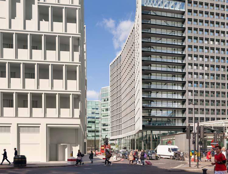
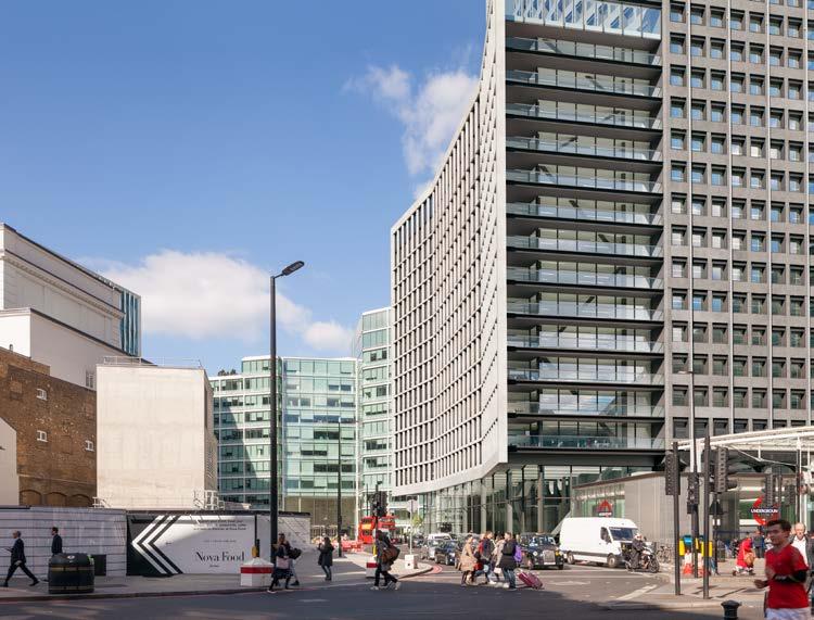
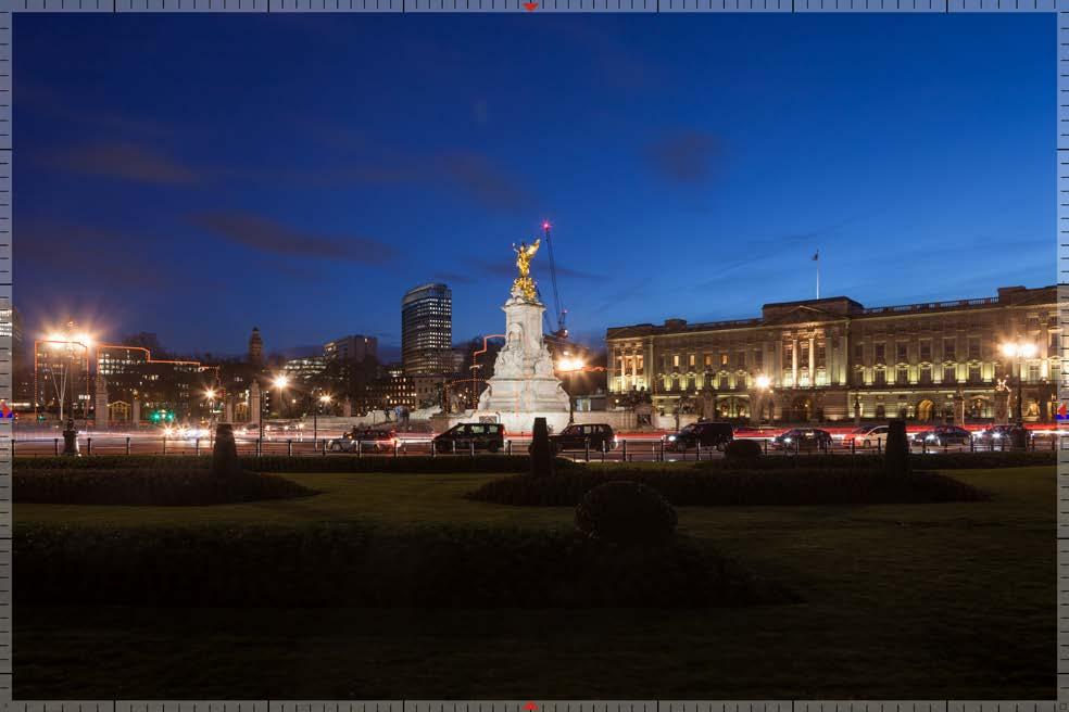
Verified
Views prepared for the planning application
submission
Views towards Victoria underground station and Bressenden Place

DEVELOPMENTS FINALISED
EXISTING CONDITION EXISTING CONDITION PORTLAND HOUSE FINALISED PORTLAND HOUSE FINALISED ALL PLANNED DEVELOPMENTS FINALISED ALL PLANNED
BEFORE BEFORE
Verified Views prepared for the planning application submission
AFTER AFTER
 View from Hyde Park towards Buckingham Palace. Portland House in the background
Competition for Yandex Headquarter in Moscow

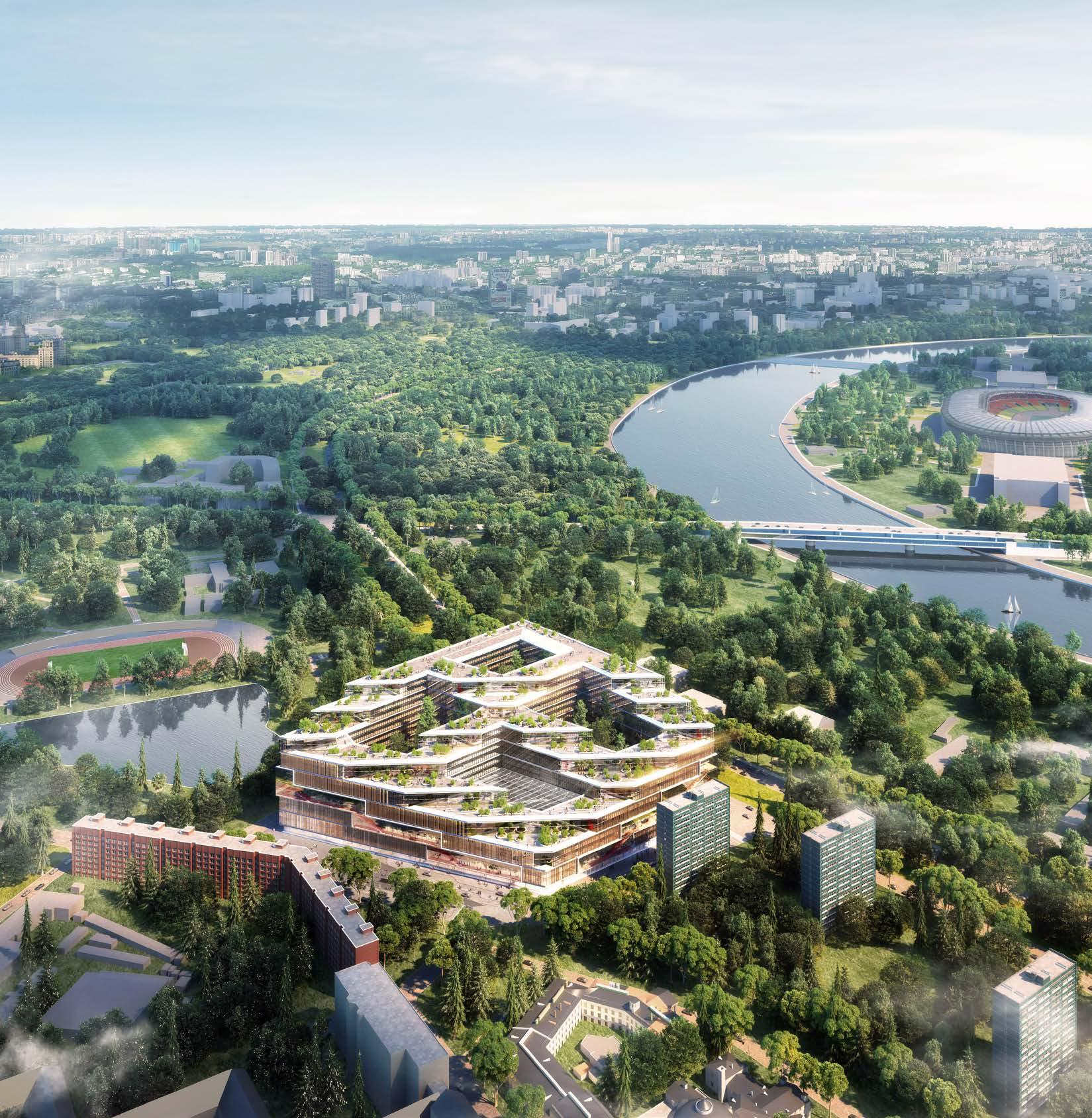
Yandex is a Russian Google. They are well known in Russia and broader Asia and in some respect used even more often than Google. The task for the competition was to design the New Yandex Campus positioned in a single consolidated location. This was a major opportunity for creating a workplace that represents the ethos of Yandex as a whole. The New Campus was to attract, retain, and develop the best talent by engaging with the wider academic and research community. Therefore it was crucial that the concepts were based on real-user feedback, and that the organisation of spaces were undertaken from the viewpoint of the staff. This was not only to increase the productivity and efficiency of the workforce, but also to encourage a collaborative and creative working environment.
We envisioned the New Yandex Campus to be an inclusive and dynamic environment, that reflects what Yandex stands for as an icon of innovation. We found that the client’s staff are youthful and dynamic, and want a work-life balance. Therefore a relaxed, but focus-driven work area will form the backbone of the scheme. This would then be supplemented generously with access to nature, and with spaces and functions to develop a healthy lifestyle. Through strategic spatial design, the project encourages interaction with colleagues both for social activities and for collaboration. Through choreography of creative functions, the building provides for a regenerative and recreational work environment.
The compositional solution of the road-path network takes into account the placement of objects of social activity on the site and possible pedestrian movements.
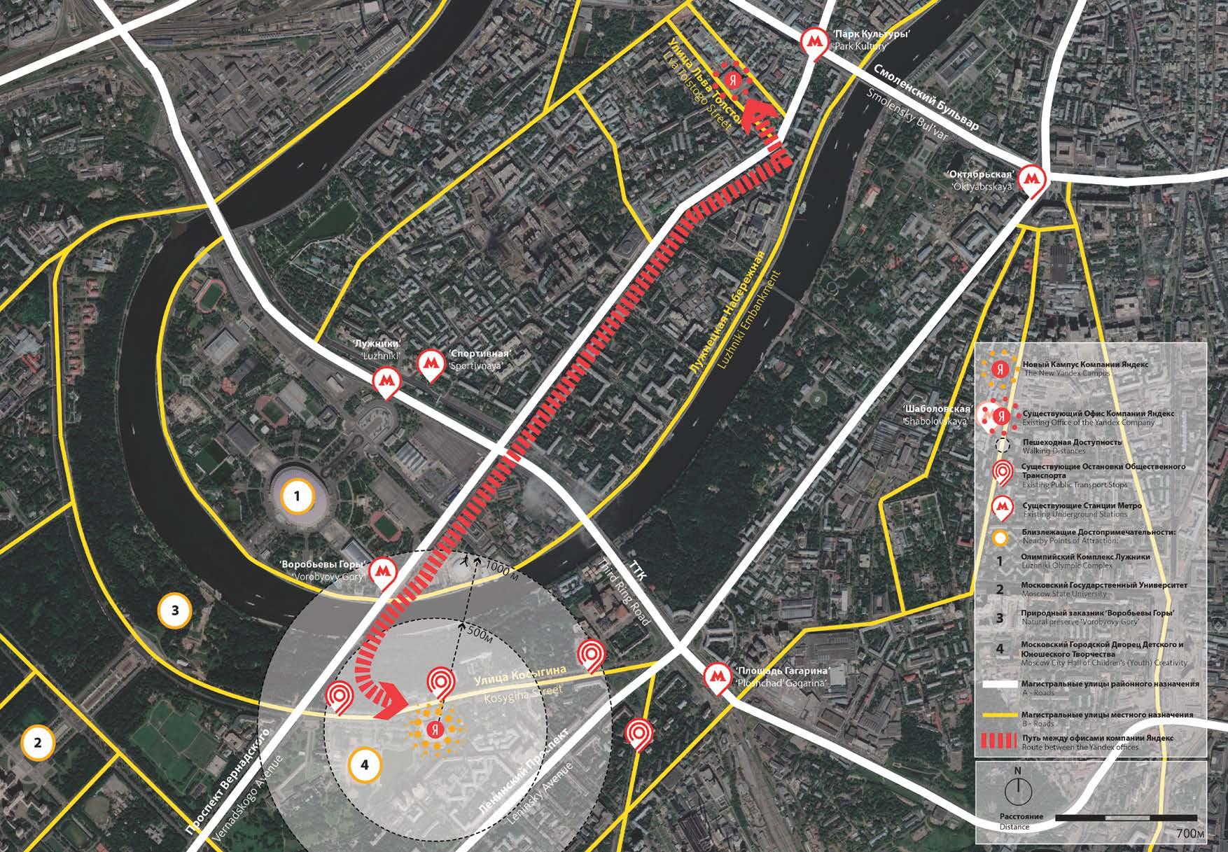
| Masterplan and transport
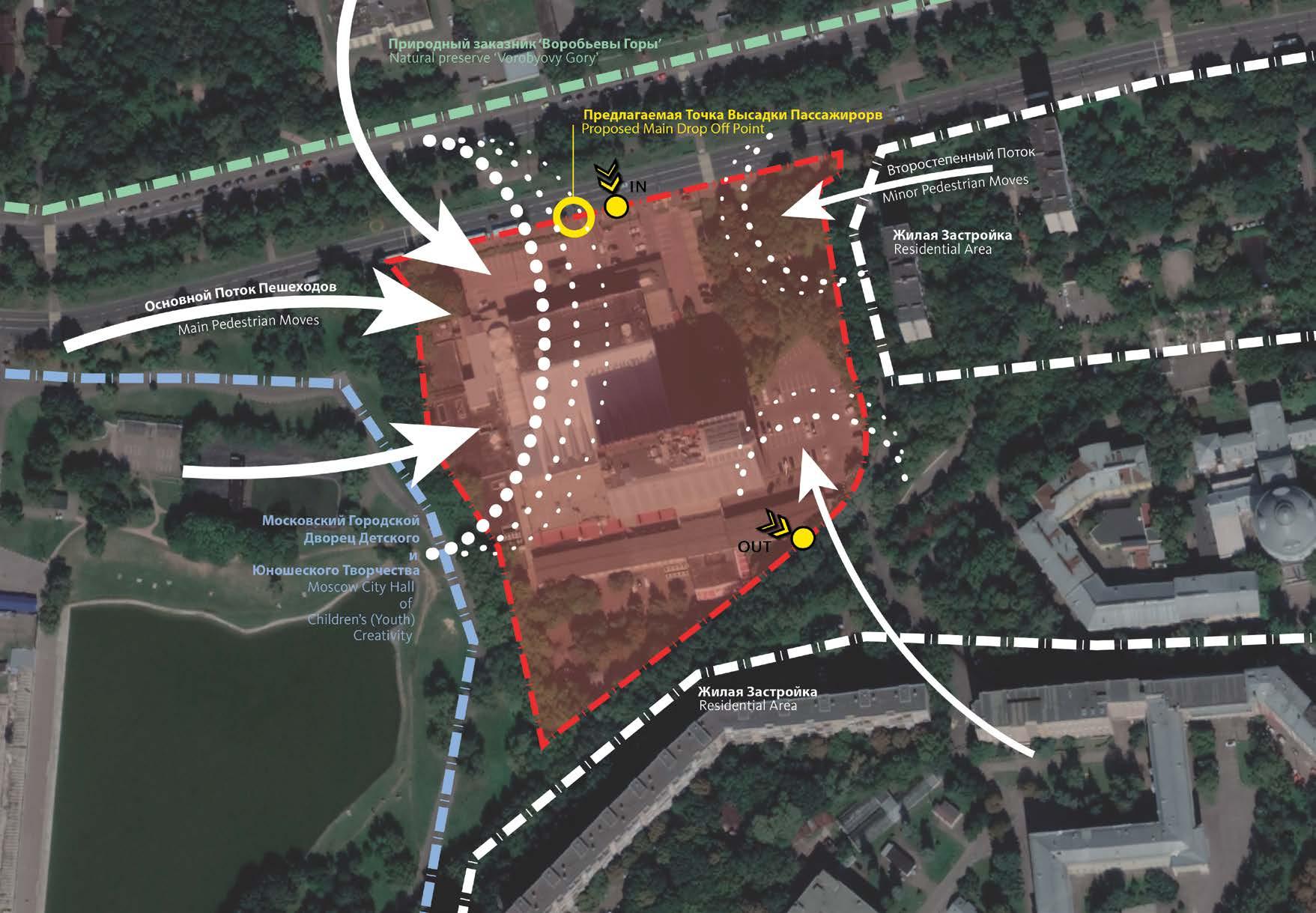
Main entry to the site held from the Kosygina street and departure from the Academic Zeldovich Street. The design was to include terraced floors at the back of the building, which will link low rising public and high rising residential buildings within the area.
Organization of transport and pedestrian traffic on the site: Main pedestrian flow is going to happen at the front of the site, while all transport moves at the back and below ground. Service and citizen transport separated on two different flows. This solution reduces the risk of congestion upon entering and leaving the site.
| Masterplan and transport
31% 56% 2% 11% 7% 6% 4% 3% 3% 3% 3% 2% 2% 2% 2% 2% 1% 1% 17% менеджер по маркетингу разработчик руководитель группы менеджер проекта другое (<1%), в т ч юристы бухгалтеры редакторы, стажеры и пр менеджер по продажам инженер дизайнер руководитель отдела системный администратор руководитель службы специалист менеджер по работе с клиентами программист менеджер аналитик контент-менеджер marketing manager product engineer group manager project manager other (<1%), incl. lawers, accountants, editors, interns, etc. sales manager engineer designer department manager network engineer division manager speciality crewman customer service manager programmer manager analys content manager 2% 2% 2% 11% 26% 40% 20% 23% 17% | Brief Area Breakdown Staff Mix 170,000 sqm 39,600 sqm 31,600 sqm 75m 12,000 GFA SITE AREA Office Education Block Food Court Sport Block Services TECHNICAL STAFF MANAGERS GENERAL STAFF OTHER PARKING TECHNICAL BUILDABLE AREA HEIGHT LIMIT CAPACITY ED SP OF FC SE
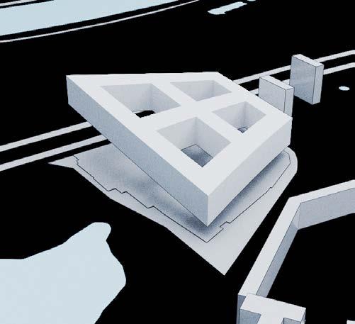
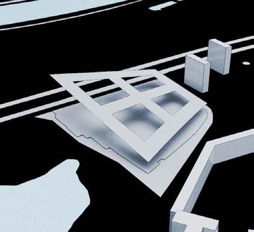
The Kernel and the Platform
Based on careful analysis of brief, and also on our accumulated knowledge of workplace design, we have established 2 core concepts that run through the design of the entire project. With this we have created the Kernel, a modular base unit that represents the way Yandex operates. The second was inspired by the rich context and the wishes of Yandex to fully embrace the public. The Platform, is the way the Kernels are organised to form a functional building, and also represent how it gives back to the community.
Kernel
A kernel is the core component of an operating system. Using interprocess communication and system calls, it acts as a bridge between applications and the data processing performed at the hardware level.
1 the inner softer part of a seed, fruit stone, or nut
2 a whole seed of a cereal a kernel of corn 3 a central or essential part
4 chiefly dialectal : a fruit seed
5 mathematics : a subset of the elements of one set (such as a group) that a function maps onto an identity element of another set Techopedia / Merriam-Webster
Approaching the design from the real-user perspective, we set out to create a base module that works as a building block for the entire project. This unit contains all the necessities for a functional working environment, with a good mix of focusdriven, social, and collaborative elements. We call this the Kernel, an essential part of the technically driven workplace:
20% PRIMARY CIRCULATION
23% SUPPORT AREAS
57% WORK AREA
THE “KERNEL” CONTEXT RESPONSE
This unit contains all the necessities for a functional working environment, with a good mix of focus-driven, social, and collaborative elements.
20% PRIMARY CIRCULATION
23% SUPPORT AREAS
57% WORK AREA
OPTIMISED WORKPLACE
The Kernels are strategically arranged upon the site in order to maximise space efficiency and daylight access into the workplace
We invite views and nature into the site, and embrace the residential and academic context towards Southeast
A FOCAL POINT COMMUNITY RESPONSE GENTLE YET POWERFUL
A heart is naturally defined, at the location where activities and circulation converge
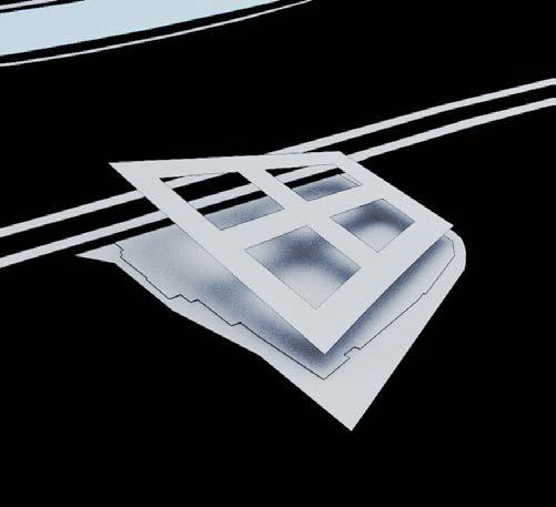
The views and daylight access of neighbouring residences are maintained or improved. The public space becomes an extension of the park
The architecture and spatial experience in tandem, forms a memorable composition that is powerful, but gently embraces and enhances the context
Towards City and Nature
Towards Neighbourhood
Metro Bus/Car Pedestrian Open Views Open Circulation
1 0 2
3 4 5 | Design Evolution
| Basic Spatial Unit
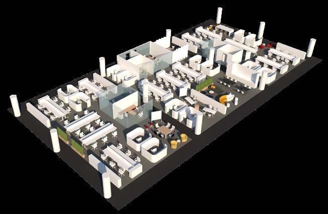
A flexible frame informed by function, efficiency, and user well-being.
The Kernel has a width of 24 meters with access to daylight and views on either side. With a generous floor-to-floor height of 4.2meters, this arrangement ensures that every part of the office block receives a good level of light. We sought to ensure the new working environment is an upgrade from the current offerings. The plan is set around a 1.5 meter square planning grid, with a suggested exposed ceiling system of 0.75 meter square grid. Together, this provides for ultimate flexibility of space planning and a fully futureproof building that can adapt to the evolution of Yandex in the long run.
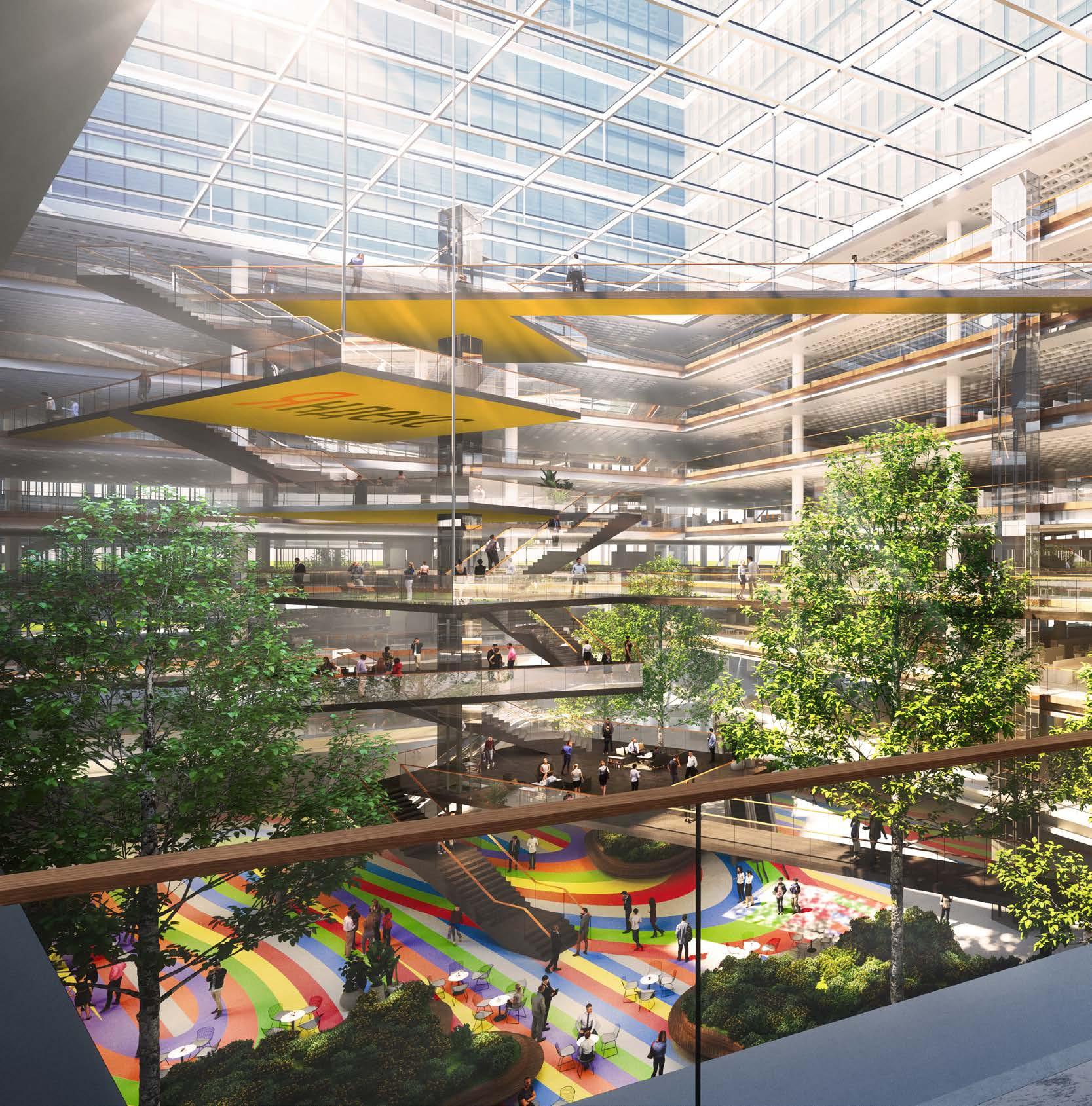
Platform
A platform is a group of technologies that are used as a base upon which other applications, processes or technologies are developed.
1 plan, design
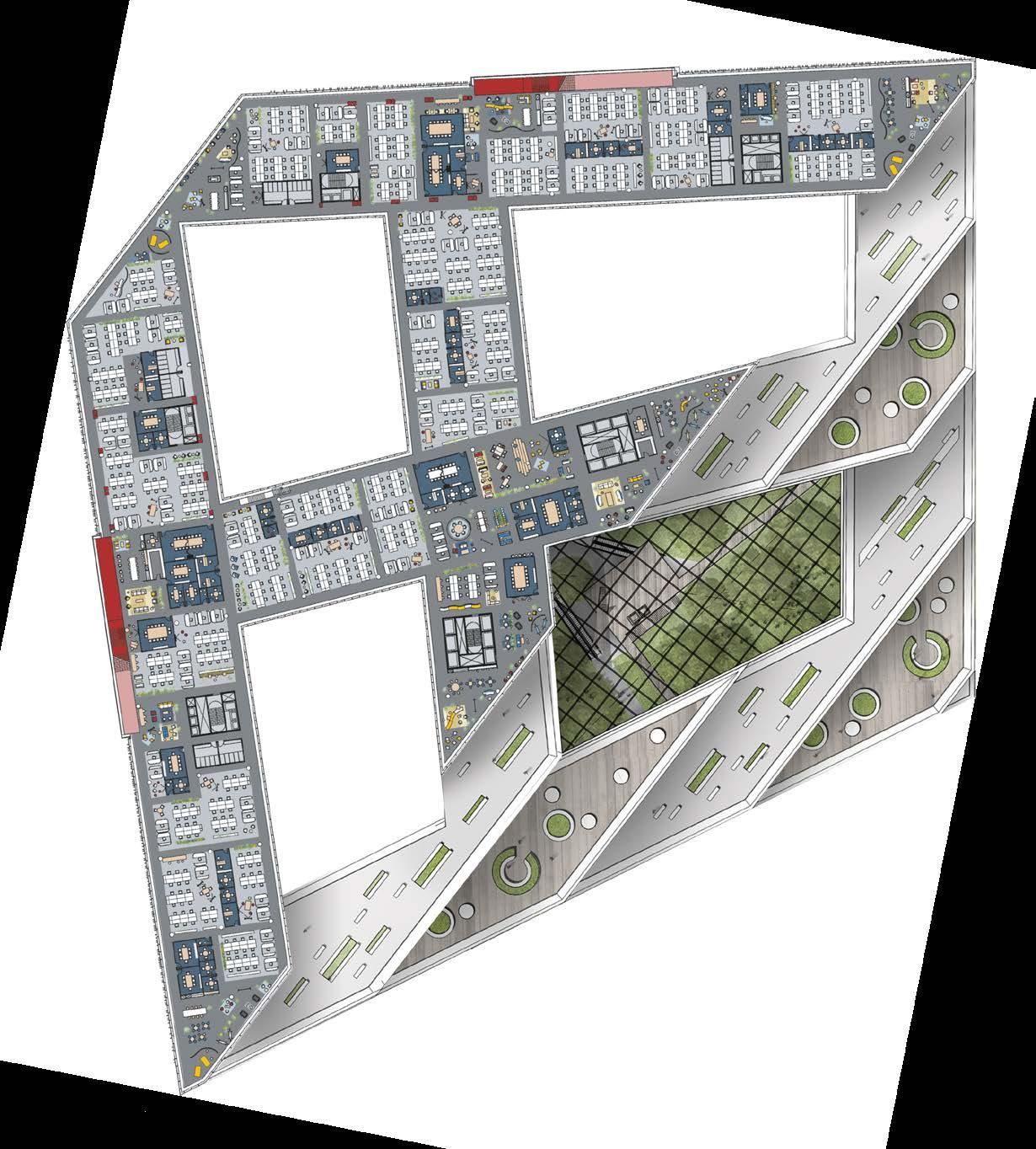
2 a usually raised horizontal flat surface especially : a raised flooring 3 a place or opportunity for public discussion
4 operating system: the computer architecture and equipment using a particular operating system.
Open workspaces and collaborative areas
Urban farming
Coffee points
Recreation Support spaces
| Platform
Techopedia / Merriam-Webster
AUTUMN GARDEN WINTER GARDEN SPRING GARDEN
SUMMER GARDEN
The three exterior courtyards situated under the lightwells would be surrounded by retail and communal services, for use both by Yandex staff and by the public.
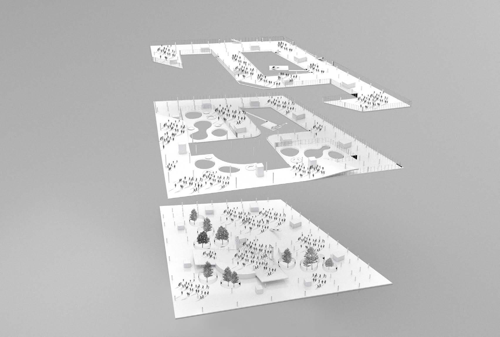
Yandex Museum will have a prominent street presence, where the Education Centre and Sports Blocks each gain their own significant entry sequence by way of the undulating landscape, leading up to level 01.
The staff and visitors are led effortlessly to the sunken main entrance, where a shared lobby, Food Court and a lush internal garden welcomes. From there, the staff can choose to travel via the Hyperlinks, or shortcut their journey through the evenly distributed lift cores.
| Platform
Staff and Visitor Main Entry at B1 Office
Grand Internal Atrium
To Education Block at L1
Education Block Car Drop-Off
Pick-up & Secondary Entry Retail and Services Open Public Courtyard
Sunken Gardens with Daylight Access to B1
Sunken Gardens with Daylight Access to B1
Yandex Museum
Exploded Axonometric of Public Realm
The visual access from the public courtyard into the Food Court and gardens will create an inclusive mood, emphasizing the community driven goals of Yandex. At the same time, the lush internal arrangement will be secured by design, creating an exclusive atrium within the building, accessible only by Yandex staff. This dichotomy is blended incrementally through the 3 external courtyards, where amenities, services, and retail functions open up to the public. The Sports and Education blocks are also situated here, to be accessed by staff and the public alike. Vegetation systems in each garden will respond to different season of the year. Therefore according to the name of the garden there will be planted different trees and bushes.
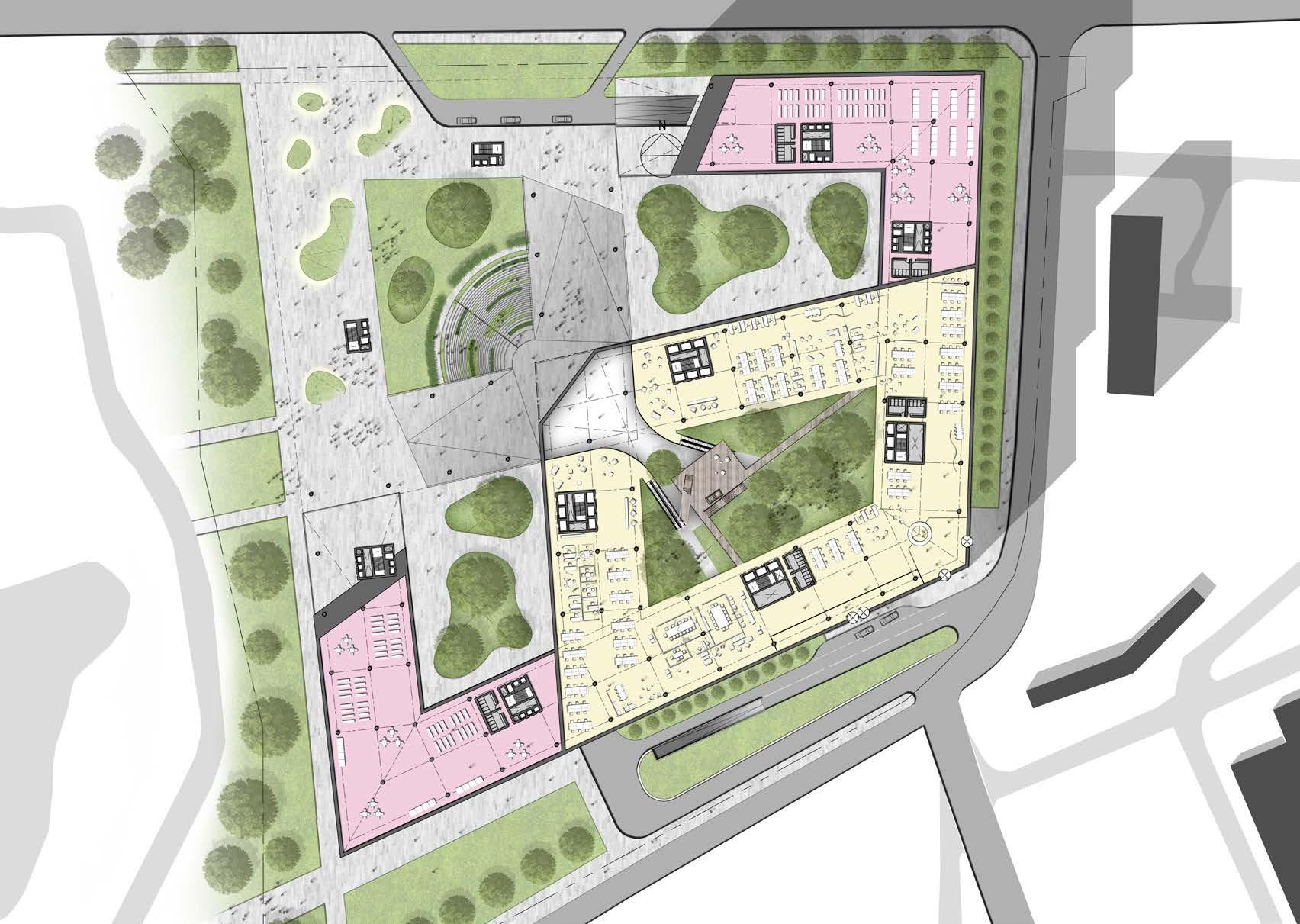
| Gardens Masterplan Layout 0 10 25 50 Yandex Museum Services / Amenities Office Atrium Entrance (below) Open Courtyard Open Courtyard Public Plaza Main Drop-off Pick-up Services Access
The suggested facade system emphasizes on simplicity of construction and maximises access to daylight and views. Glare is one of the key annoyances for a technically driven workplace, which we sought to control by means of a series of slender louvres.
These louvres open up towards view at a perpendicular angle, where at an angle it works as a preventive measure for glare. The materiality is envisaged as natural timber, further strengthening our desire to bring a natural touch to the work environment, and bring warmth via the diffused light reflected off the louvres.
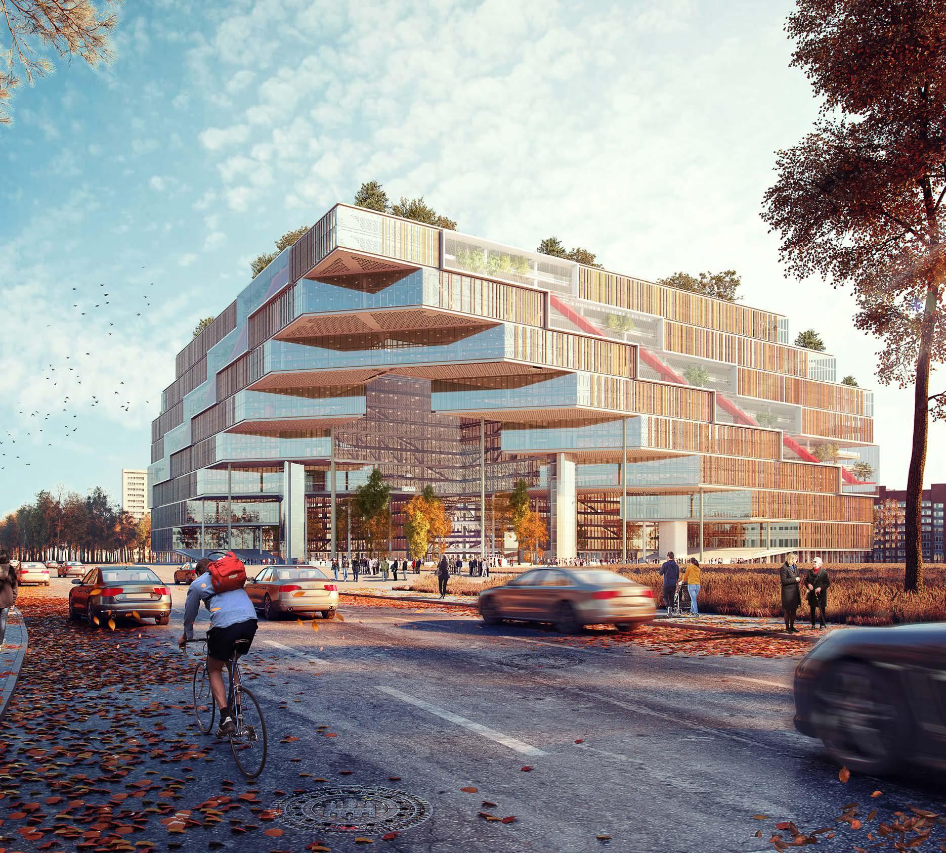
| Facade
We envisaged the public realm as a space that would be activated throughout the work day and into the evening. This would attract not only the immediate neighbours, but also the larger community of the University Campus and Institutions.
By facing the public space and retail functions towards the Northwest, and by containing them within the courtyards of the building, we have effortlessly sheltered the bustle of this area from the more quiet and calm residential neighbourhood.
The overhang of the building poses a unique opportunity to enhance the iconic image of the building, by introducing dynamic light installations.
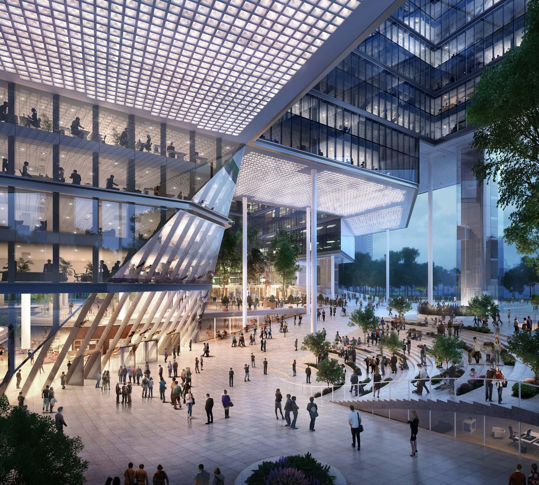
| Public Realm
| Roofscape
The roofscape solution of the building is dictated by the terraced architectural form.
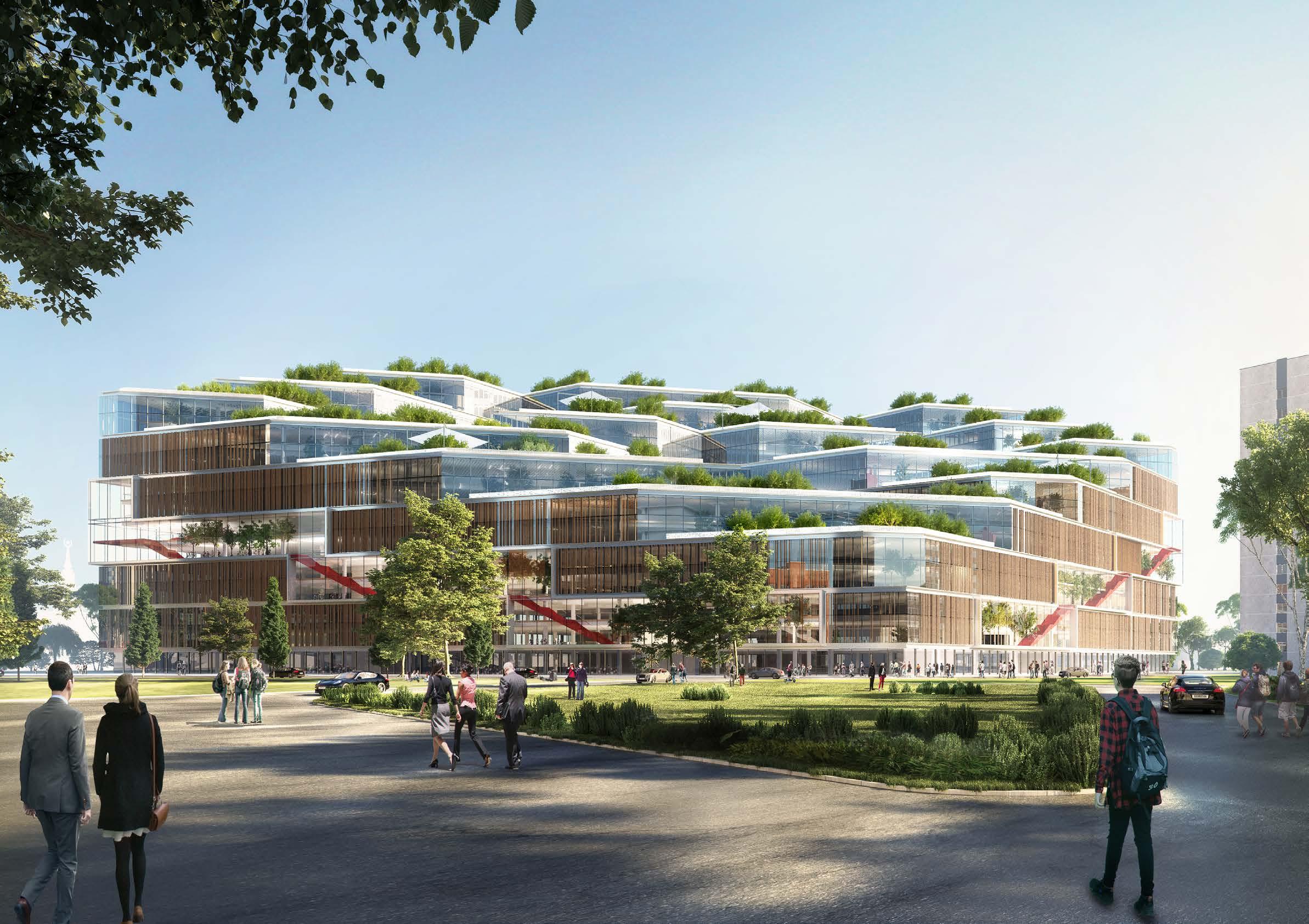
It is proposed to plant meadow flowers on the roof, trees in pots and small shrubs, the ones who can survive in the cold winter and hot summer temperatures.
Plants offered for planting are Oliva, Birch, Japanese Maple, Boxwood, Dogwood Cotoneaster, Heather.
During extremely cold temperatures it is proposed to temporarily remove plants to the internal garden of the building.
Phase 1 Basement 01 Basement 03 and 02 | Basement Plans 0 25 50 100 Phase 1 Ground Level Phase 1 BASEMENT CORE ROOF Office Education Block Food Court Sport Block Services ED SP OF FC SE
Phase 2 Basement 01 | Plans 0 25 50 100 Level 01 Phase 1 Phase 2 Phase 2 Ground Floor BASEMENT CORE ROOF Office Education Block Food Court Sport Block Services ED SP OF FC SE
| Plans Level 04 Level 03 Level 02 Level 07 Level 06 Level 05 BASEMENT CORE ROOF Office Education Block Food Court Sport Block Services ED SP OF FC SE
| Plans Level 10 Level 09 Level 08 Level 13 Level 12 Level 11 BASEMENT CORE ROOF Office Education Block Food Court Sport Block Services ED SP OF FC SE
Level 15 Level 14 Roof Plan | Plans BASEMENT CORE ROOF Office Education Block Food Court Sport Block Services ED SP OF FC SE
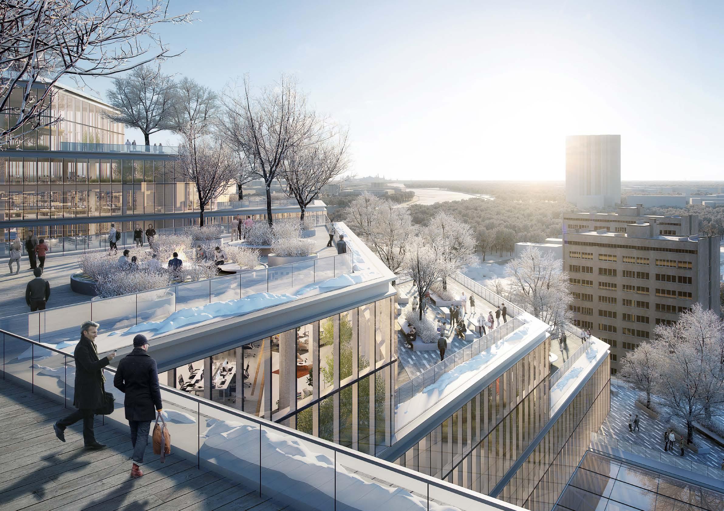
Beauty Experimental Academy Competition
Bonjour!
14 Rue Royale, Paris
Next project is the competition for an innovative beauty academy located on 14 Rue Royale in Paris. The existing building including surrounding properties are listed. The task was to create modern, open space without affecting the buildings except one facade. The program and strategy for the project was prescribed by the client. Sample of uses are shown on the plans on the next pages.
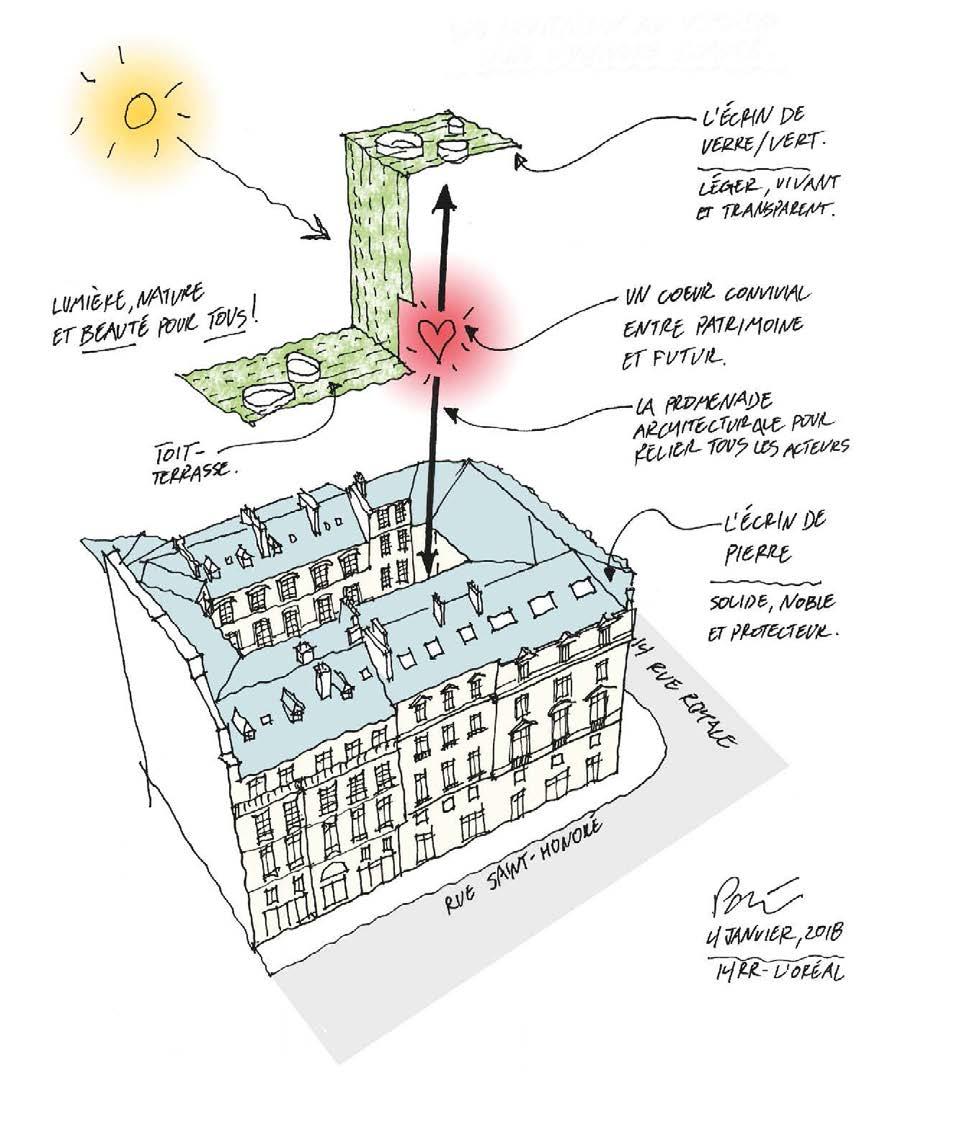
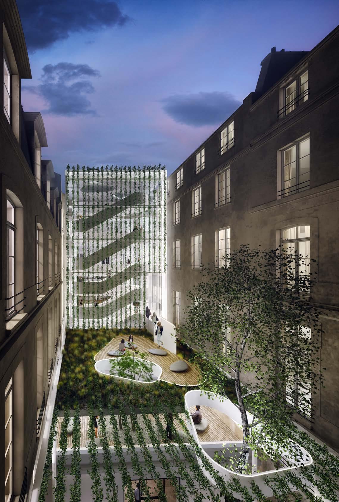
Since the building is a typical French housing it has fairly small floorplates and it is 5 levels high in total. The concept was to create connectivity between the floors and uses by creating feature stairs looking like a sculpture from the outside - the heart of the building. To minimize the visual impact on the surrounding listed buildings the new extension with a staircase was hidden’behind a green wall. The circulation areas are around the internal courtyard and the spaces are located towards the outside of the floorplate. The design is very light, subtle and not dominating in its appearance. The use of light, pastel colours and natural materials give a great background to the creative beauty activities happening in the building.
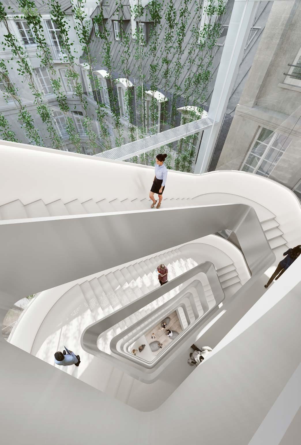
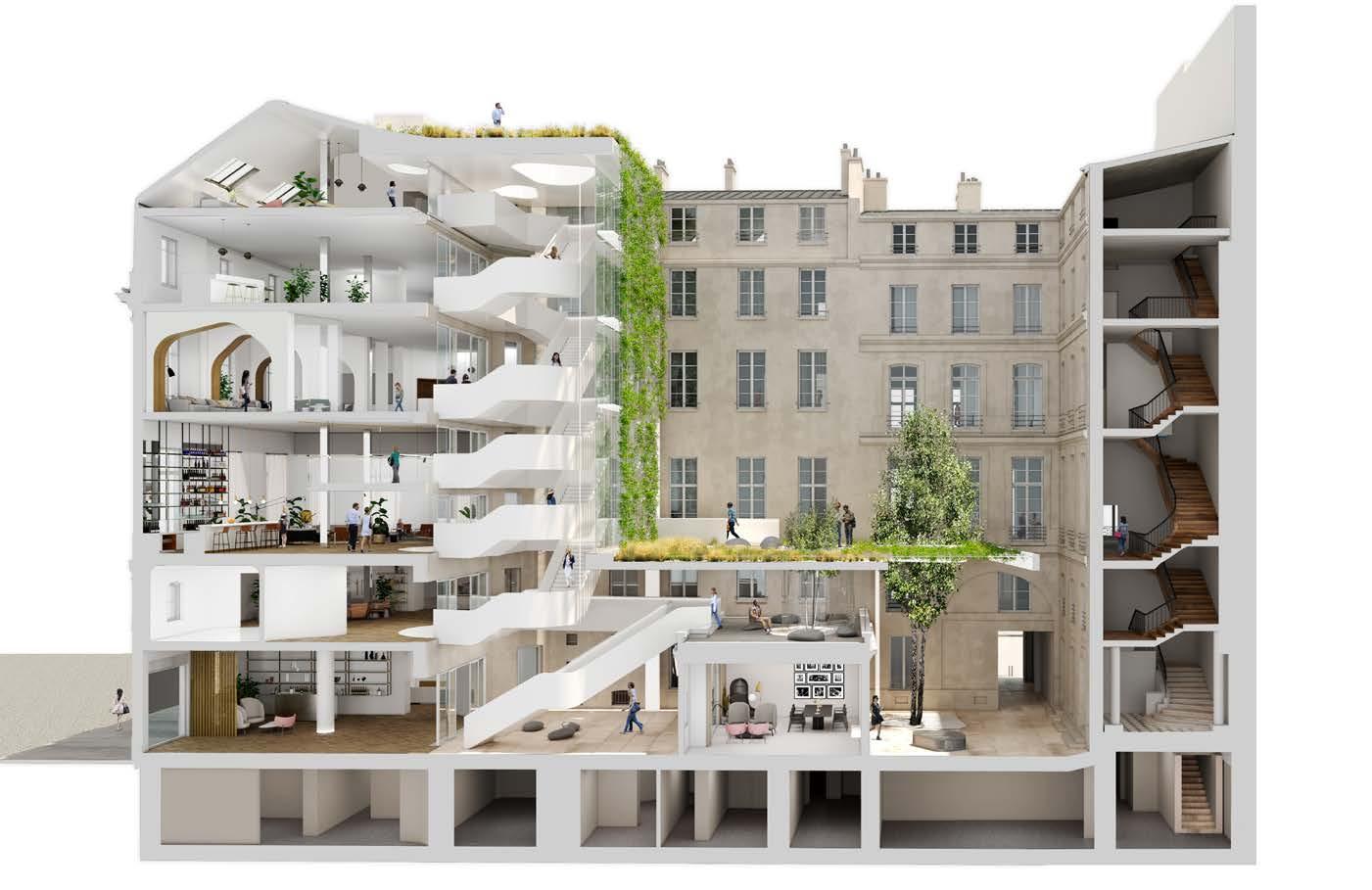
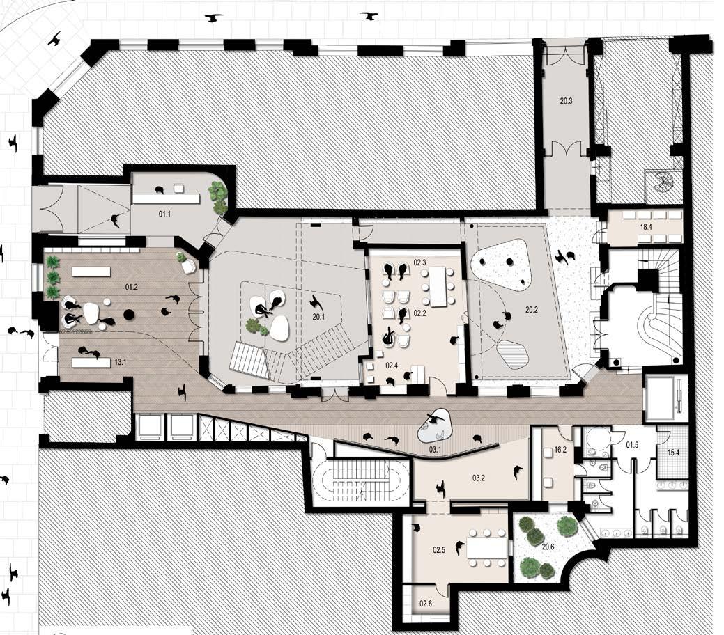
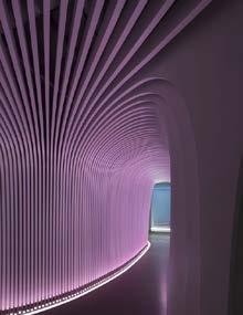
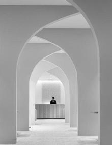

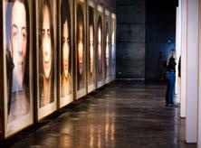
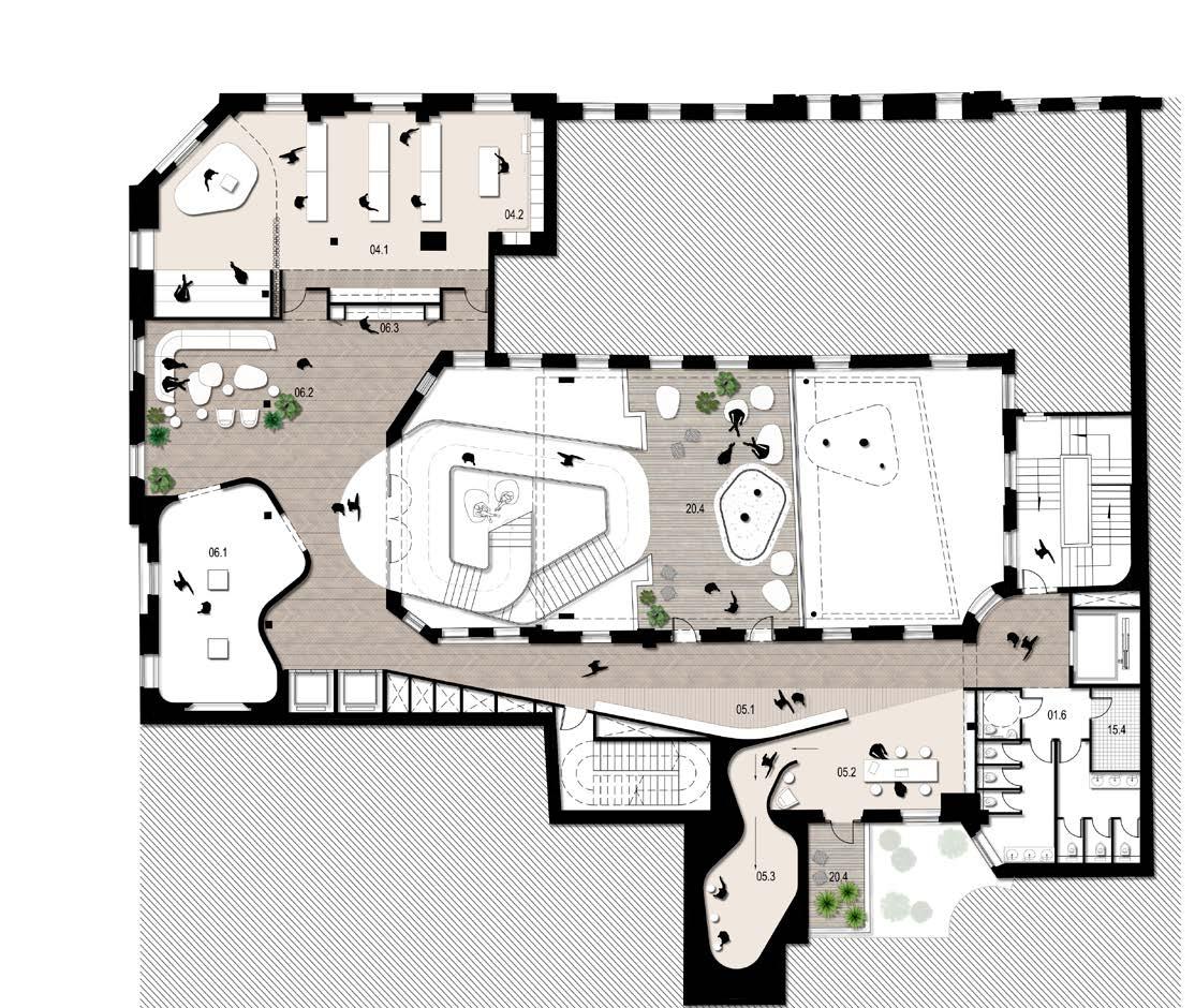
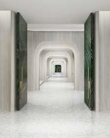

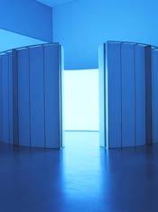
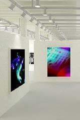
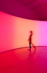
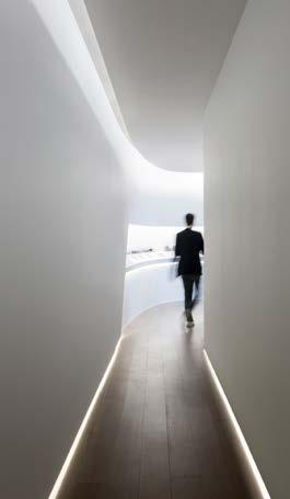
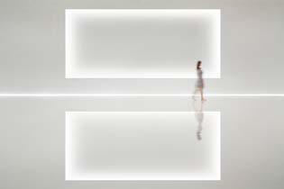

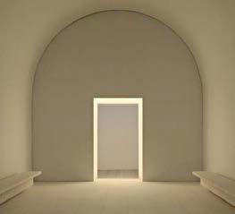
Ground Floor Plan First Floor Plan 01.1 Hall of Beauty 06.3 Material Library and Sensorial Room 06.1 White Cube
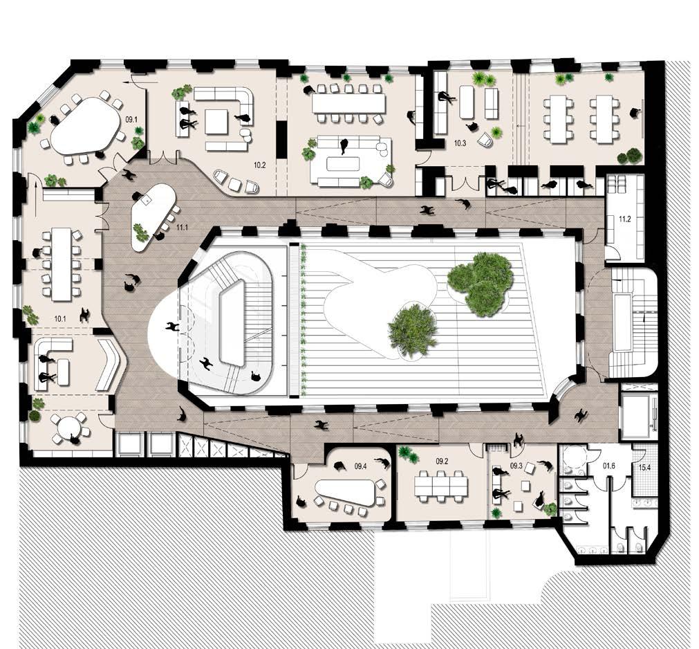
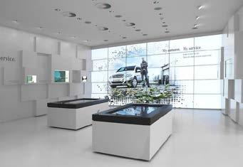
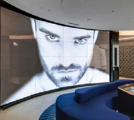

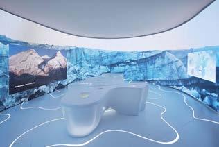
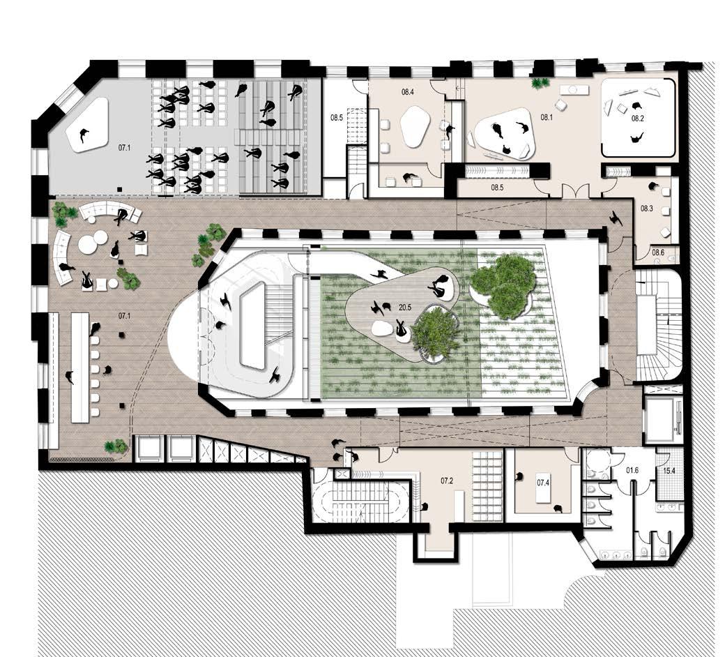
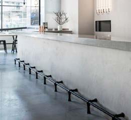


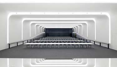
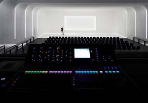
Third Floor Plan Second Floor Plan 07.1 Bar / Lounge 09.4 Web Listening 07.1 Transformer Space
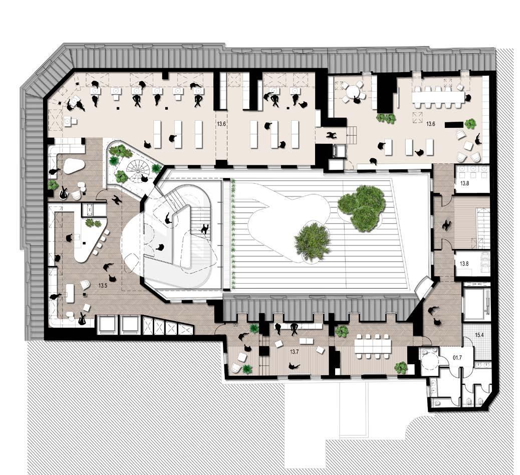
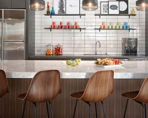

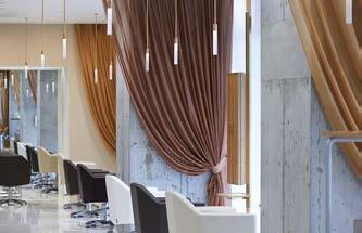
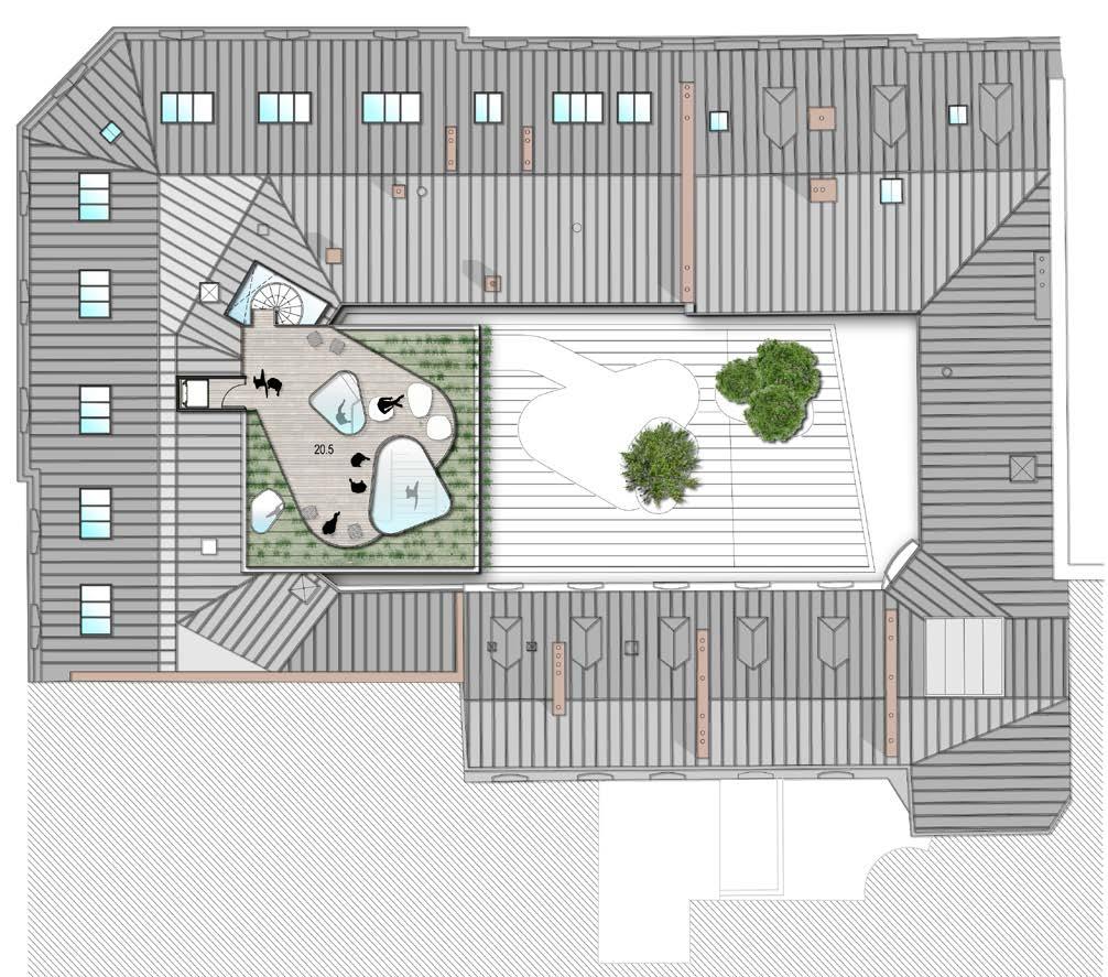
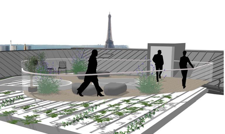
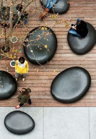
Fifth Floor Plan Roof Top Plan 13.6 Technical Space 20.5 Terrace
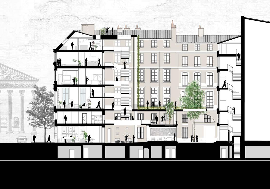
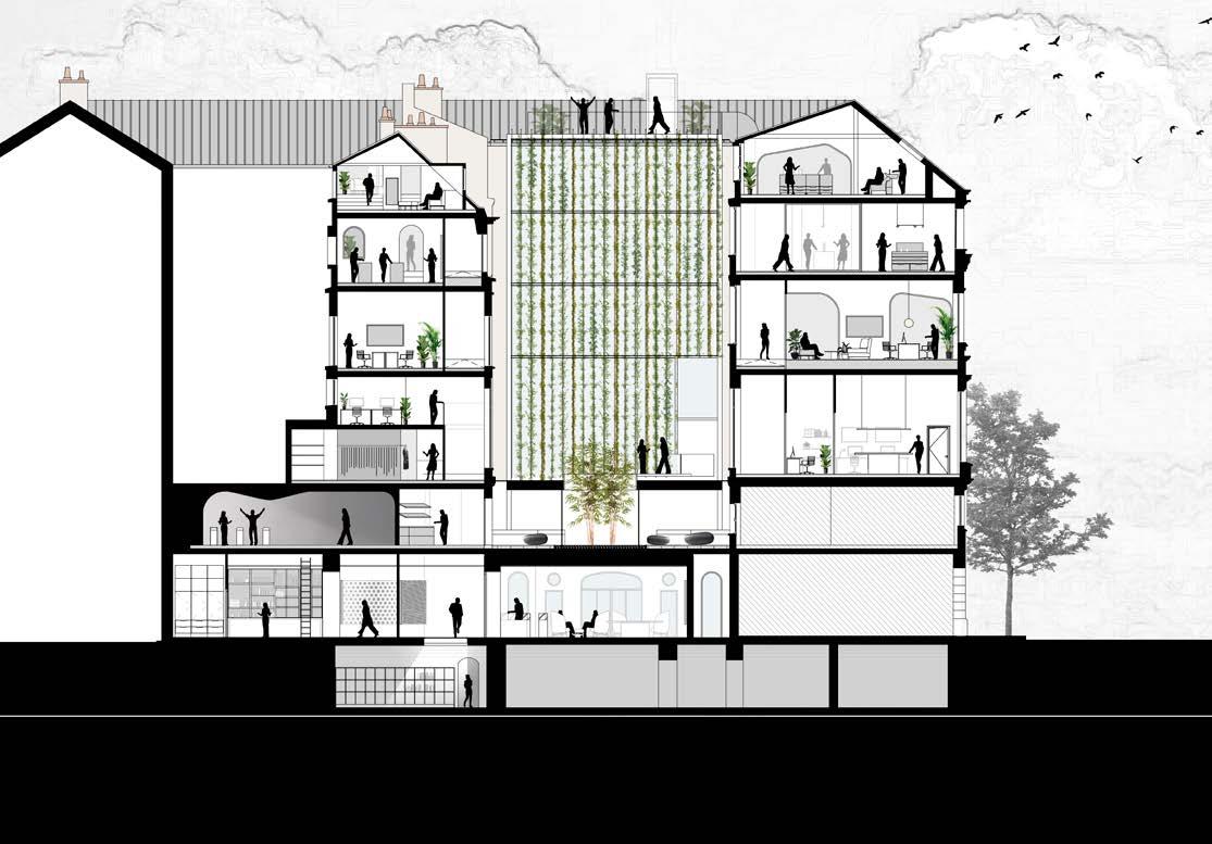 Cross Section
Longitudinal Section
Cross Section
Longitudinal Section
Merci!
ONE FAIRCHILD
Highgate Shoreditch Hotel is a 33,900-sqm mixed-use development located in the heart of London, Shoreditch, an area of dynamic social, physical and economic change.
Positioned at the southern point of the Shoreditch Triangle on a site not currently fulfilling its potential. The development will become a key addition to East London’s creative community, the local economy and nearby residents in Hackney.
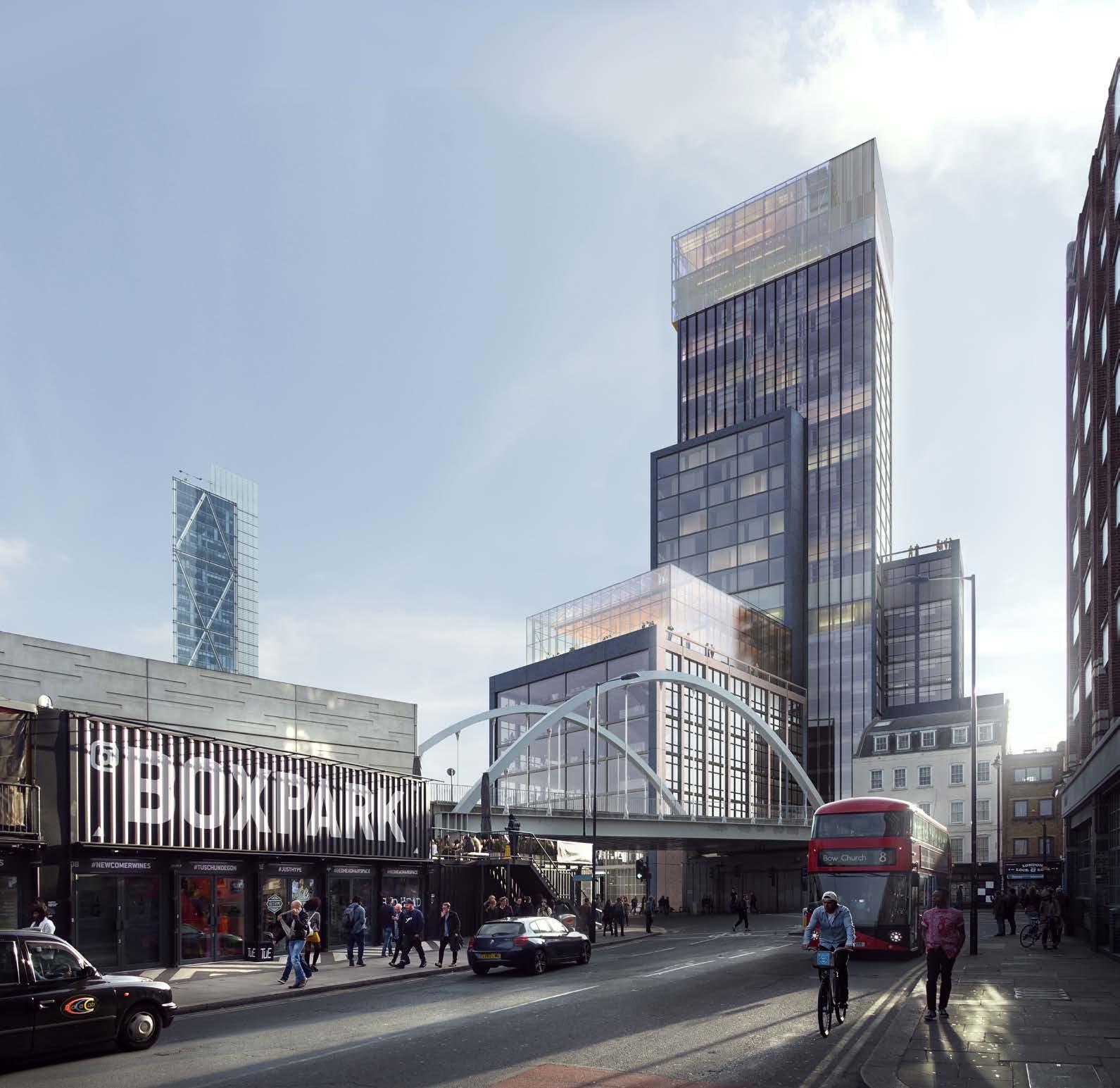
Designed by Gensler, the scheme pays tribute to Shoreditch’s rich industrial legacy while delivering a contemporary piece of architecture that consists of commercial office space, shared amenities, food & beverage, events spaces and a 200-room hotel, defined by glass volumes stacked on top of one another to break down the scale and resonate with the rhythm of the urban grain.
Through its conscientious mix of uses, Highgate Shoreditch Hotel will introduce an important interplay between places to work, meet, eat, drink and enjoy, creating a number of different activities collected together as a microcosm of the neighbourhood. It will also contribute to Shoreditch’s wider regeneration programme, producing new jobs for the area, boosting the local economy and driving forward improvements to the physical environment for the London Borough of Hackney.
SITE STRATEGY
The site stands at an important gateway into the borough, marked by the Great Eastern Street / Shoreditch High Street / Commercial Street road junction. This forms one of three nodes that define the Shoreditch Triangle. The nodes are important infrastructural junctions that frame the triangle, with all three featuring tall elements.
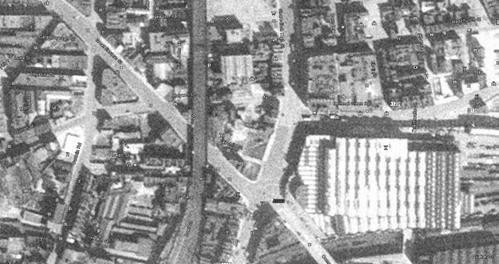
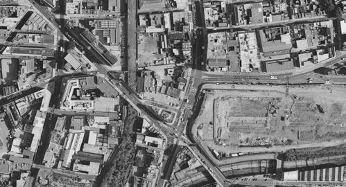
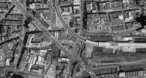
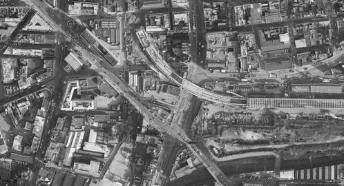
Shoreditch has undergone so much physical, social and economic change in the last few decades that it’s barely recognisable from the industrial manufacturing and residential neighbourhood it used to be, which for the most part, has been replaced with creative agencies, tech start-ups and independent shops, bars and restaurants.
This location provided a fantastic opportunity to add to this diverse economy with a building that complements Shoreditch’s mixture of activities while remaining within the scale of the nearby City of London.
SHOREDITCH HIGH STREET SHOREDITCH HIGH STREET OLD STREET OLD STREET COMMERCIAL STREET GREATEASTERNSTREET HACKNEYROAD RHODASTREET FRENCH PLACE DEREHAM PLACE STREET SWANFIELD STREET DUCAL TOMLINSONCLOSE ARNOLD LANE CIRCUS BRICK STREET VIRGINIAROAD BOUNDARY STREET HOCKER STREET BOOT STREET PAUL STREET RAVEY CHANCE STREET REDCHURCH STREET Mark Square BRICK LANE NEW INN YARD NEW INN YARD BACON STREET PHIPP COURT GATESBOROUGH STREET MARK STREET BETHNALGREENROAD WHITBY STREET LUKE STREET WILLOW STREET ANNING STREET LIGONIER STREET CAMLET STREET BOUNDARY STREET OLD NICHOL STREET NEW INN CURTAIN PLACE BLACKALL STREET LEONARD STREET CLUB ROW RAVEY STREET Willow Court NAVARRESTREET RIVINGTON STREET TURVILLE STREET NEW SCRUTTON StJames's Approach NORTH CHRISTINA STREET ROCHELLE STREET HOXTON SQUARE BOUNDARY STREET NAVARRESTREET CALVERTAVENUE BATEMAN'S ROW BOUNDARY PASS CHARLES SQUARE CHARLES SQUARE GREATEASTERNSTREET GREAT EASTERN STREET GARDEN WALK CLUB MONTCLARE STREET ROW CAMLETSTREET MONTCLARE STREET
AUSTIN STREET LEONARD STREET VANDY STREET FLEUR DE LISSTREET TABERNACLE STREET STREET DYSART PAUL STREET WORSHIPSTREET WORSHIP STREET COURT PLACE HOLYWELL ROW CURTAIN ROAD AVENUE HOLYWELL LANE SHUTTLE COURT AND FAIRCHILDSTREET CROWN HEWETT STREET PLOUGH YARD PLOUGH YARD CLIFTON HEARN STREET MOTLEY ELDER STREET STREET BRICK LANE QUAKER STREET CURTAIN ROAD PALISSY PADBURYCOURT CHARLOTTE ROAD CALVERTAVENUE CHARLES SQUARE EBOR STREET PLACE CHARLES SQUARE CHAMBORDSTREET STREET SCLATER STREET FAIRCHILD STREET Ps Ps Ps HOLYWELL LANE REDCHURCH STREET CALVIN WHELER STREET WILSON STREET STREET BLOSSOM STREET APPOLD STREET DYSART STREET JEROME STREET FLEUR DE LIS STREET COMMERCIAL STREET Court GREY EAGLE STREET CORONET STREET 0 20 100 200 50 1 2 1945 2008 1999 2014
SHACKLEWELLSTREET
3
SITE STRATEGY
The heat map demonstrates the differentiation of heights within the project’s context and the fluid continuity between different tall building clusters in The City to the South.

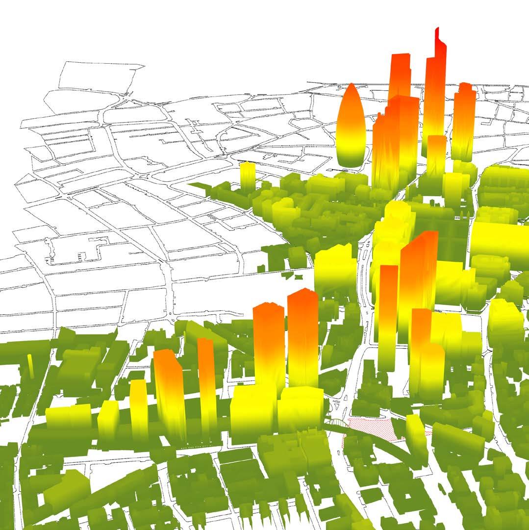
Based on a detailed context analysis and early massing studies, it became apparent that a tower typology would be unsuitable for the site. Despite its close proximity to tall buildings, the design attempts to create a building form more in sympathy with the character of Shoreditch, with the following design directives:
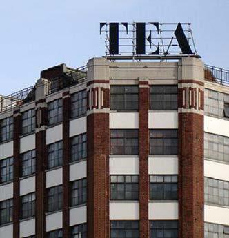
• Install transparent and porous building frontages to enliven street activity & vitalise neighbourhood life
• Create a diverse collection of building uses to cater for local economic demand
• Integrate public shared events space at mid-levels, sensitive to the surrounding townscape
• Open a semi-public neighbourhood lounge & club space at the top of building
• Alleviate traffic on Fairchild Street through shared managed public space
• Continue the economic, social and cultural development of Shoreditch & The City.
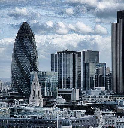
SITE
SHOREDITCH TO THE NORTH
THE CITY TO THE SOUTH SITE
SITE STRATEGY
The building will mediate between its two neighbouring communities; Shoreditch and The City, two distinct environments in which very different activities, personalities and atmospheres exist.
The concept focuses on creating a building within its context that showcases the diverse mix of activities in the area.
Key decisions made in the design strategy are a direct response to the project’s location, producing a building form that sits fittingly amongst a cluster of existing or permitted tall buildings. The strategy also responds to the rhythm of the urban grain and the variety of activities, personalities and atmospheres that exist in the area.
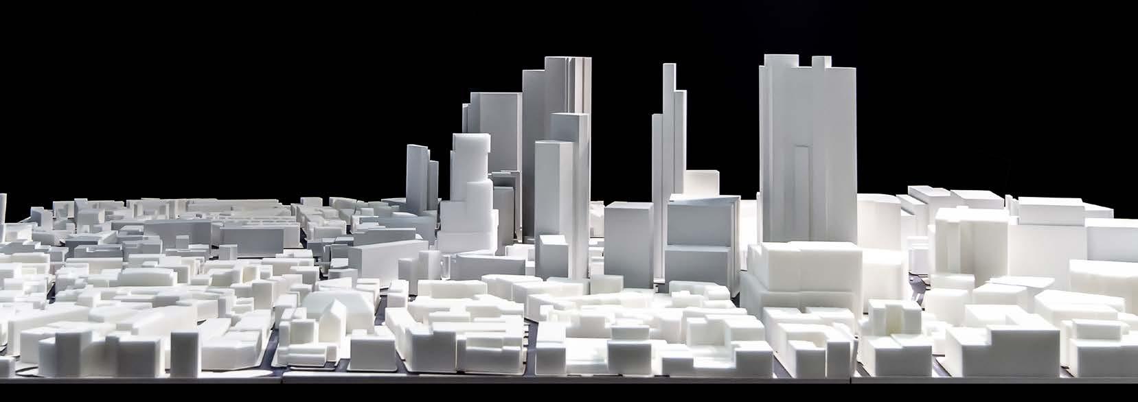
TOWER CITY SHOREDITCH CITY SHOREDITCH CITY SHOREDITCH TOWER + PODIUM URBAN INFILL TOWER CITY SHOREDITCH CITY SHOREDITCH CITY SHOREDITCH TOWER + PODIUM URBAN INFILL TOWER CITY SHOREDITCH CITY SHOREDITCH CITY SHOREDITCH TOWER + PODIUM URBAN INFILL
MASSING - A NEW MIXED USE BUIDLING TYPE
The massing is formed by a sequence of volumes that relate to the grain and the multiple uses and users in Shoreditch.
Stacked on top of each other, the location, proportions and dimensions of these volumes are defned by the activities that will exist within them and their planes ofset to diferentiate these uses.
This arrangement generates a distinctive visual relationship between the volumes and their context. The shifts between volumes create visually distinct edges, ledges and terraces that animate the perception of the building from the surrounding area, with diferent perspectives on its form, depending on the position of the viewer.
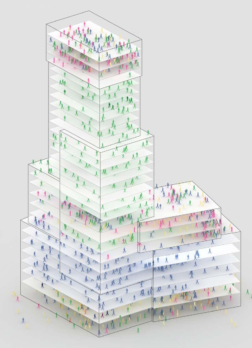
The base aims to encourage pedestrian accessibility with a change in volume after the frst level. The second datum is a similar height to existing buildings in the area such as the Tea Building and Shoreditch House.

The building’s tallest elements are located at the southwest corner of the site with the aim of moving the height away from Shoreditch High Street and Holywell Lane to reduce the impact on the adjacent plots.
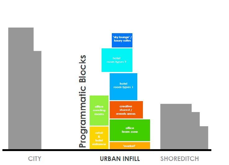
The Southwest corner has two volumetric moves that interrupt the verticality and tallness of the building while still achieving a clean, crisp corner.
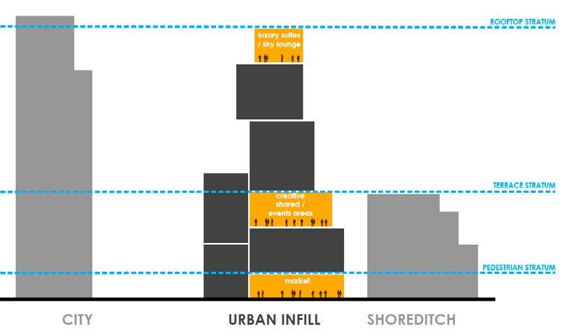
ORIENTATION AND MATERIALITY

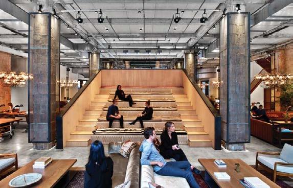
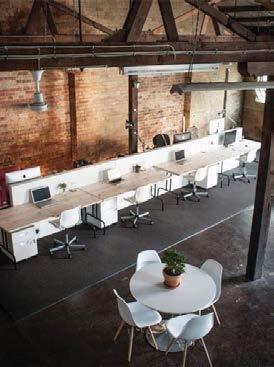
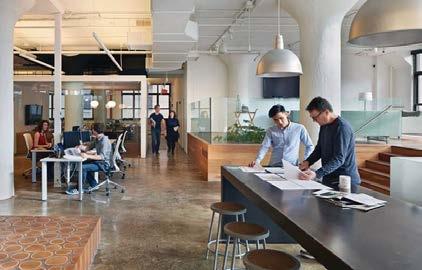
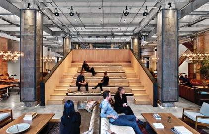

The materiality takes inspiration from the local urban grain with a raw, gritty and dynamic appearance. The façade design is rational, timeless and allows the right amount of transparency to create a dialogue between the inside and the outside. The base appears solid and robust with concrete which will age well and unite with its surroundings in time.
Mid-levels combine the expression of the concrete structure, with black metal fenestration and glass. The dark metal intends to remind the viewer of the factories, warehouses and loft buildings that once stood nearby. The façade colour gets lighter as the building ascends, culminating in a glass volume lightly cantilevered at its highest point.
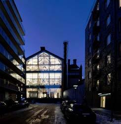
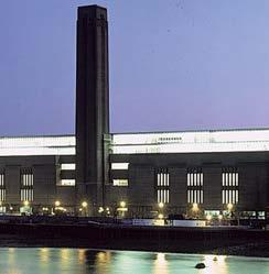
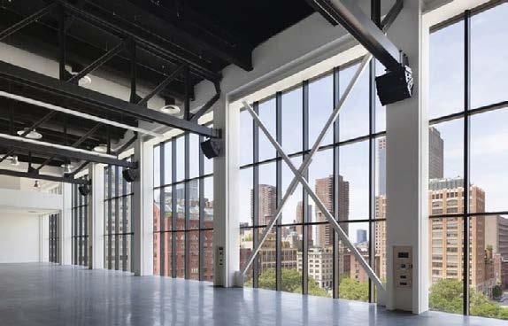
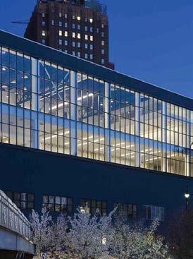
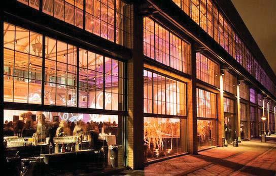
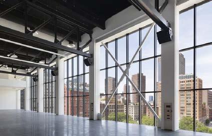
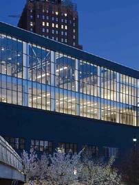
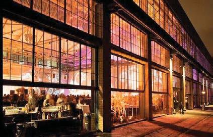
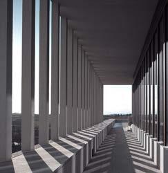
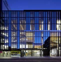
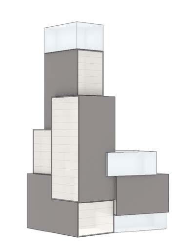
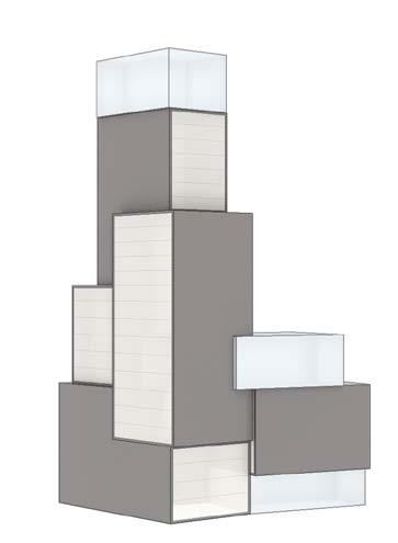
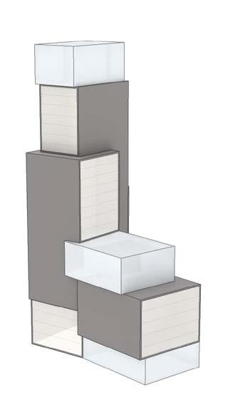
Dark grey pre-cast concrete panels are assembled at the base and lower levels of the building. At upper levels, the solidity continues with glassfibre reinforced concrete, a much lighter material that provides the same quality finish and colour as the concrete to create continuity.
All framed glass is black metal which harmonises the concrete and the glass. The tallest volume is articulated with vertical aluminium that emphasises the slenderness of the volume and acts as a crucial shading element to achieve the desired energy model.
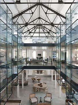

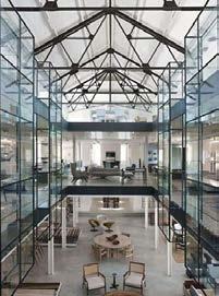
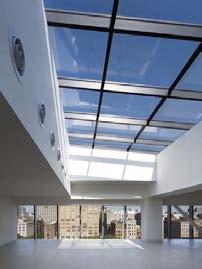
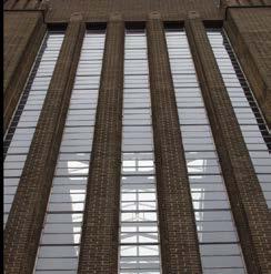
Fairchild Street Fairchild Street from terrace to The City West East to The City Co-working Events Space Exposed structure Black/dark metal Soild/robust base Vertical articulated 22 SOCIAL SKYLIGHT INDUSTRIAL PROGRAM: OFFICE SKY BRIDGE COMMUNAL SPACE FLEXIBLE WORK-LONGE SPACES -OPEN SOCIAL SPACES -WORK & RELAX -FEATURED GLAZING MATERIALITY SOCIAL SKYLIGHT URBAN MODERN PROGRAM: OFFICE SKY BRIDGE COMMUNAL SPACE SOCIAL SPACES -WORK & RELAX -FEATURED GLAZING MATERIALITY 2. ‘The Shed’ 3. ‘Sky Lounge’ 1. ‘The Market’ 2. ‘The Shed’
FINAL DESIGN, LEVELS
'THE MARKET' - LOWER GROUND FLOOR
'THE MARKET' - GROUND FLOOR PLAN
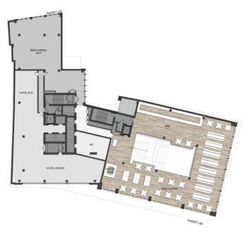
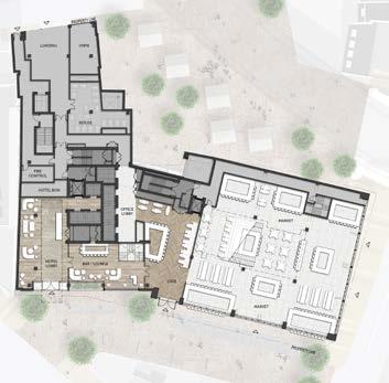
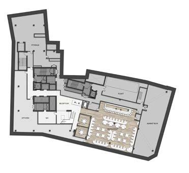
'THE MARKET' - LEVEL ONE PLAN
The final design consists of a 200-room hotel and 11,866-sqm of creative office space, covering an overall area of 29,640-sqm of floor space in total.
The scheme is defined by three glass boxes. The base, called ‘The Market’, is highly permeable and accessible to pedestrians.
The mid-terrace level called ‘The Shed’ offers gathering space for lectures, presentations and other amenities. Finally, the top box named ‘The Sky lounge’ offers a more intimate and exclusive space where visitors can enjoy views of London.
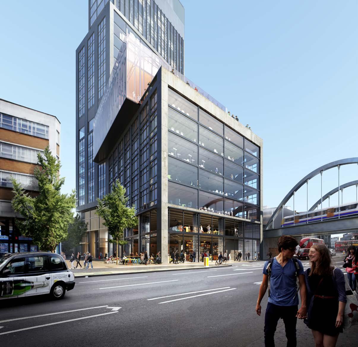
FINAL DESIGN, LEVELS
THE OFFICE - LEVELS 2 TO 4
THE OFFICE - LEVELS 5 TO 6
'THE SHED' - LEVEL 7
Levels 1 – 2 | The Market
The base comprises of shared space that can be enjoyed by the local community, with restaurants, break out spaces and other ancillary areas to the hotel.
Levels 3 – 6 | Office
Flexible office space that can be adapted to suit a diverse mix of tenants but following the reoccurring needs of spaces for a creative and contemporary community.
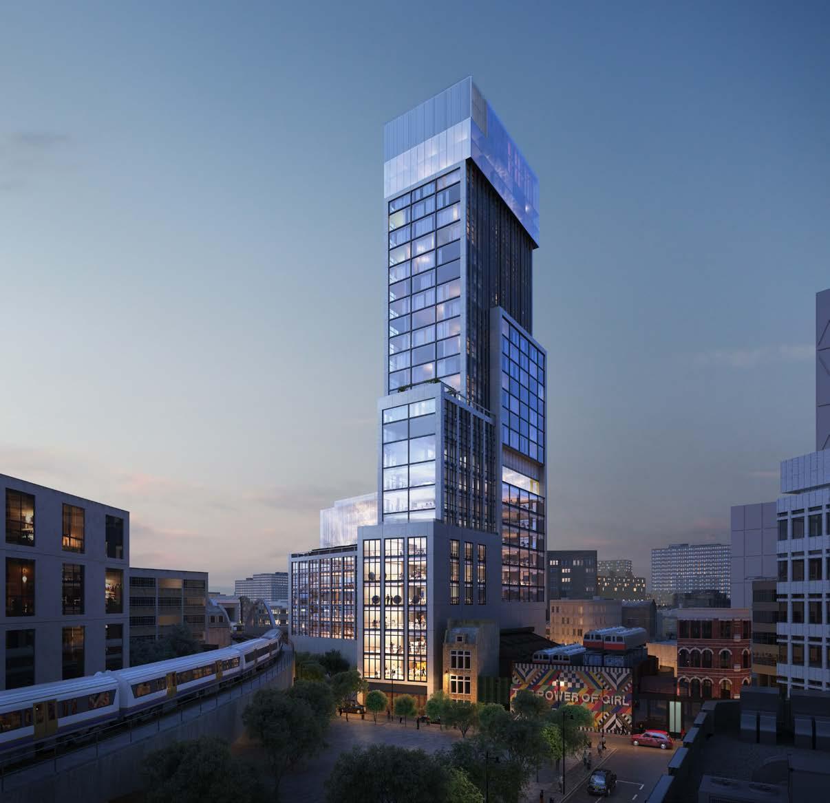
Levels 7 – 9 | The Shed
A triple height shared communal space for office workers, with gathering areas, food & beverage and breakout space. Activities such as conferences, talks, lectures, events, art exhibitions will animate this space.
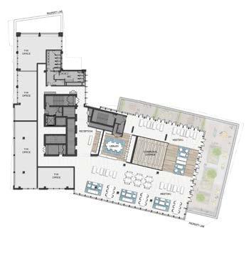
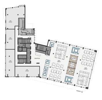
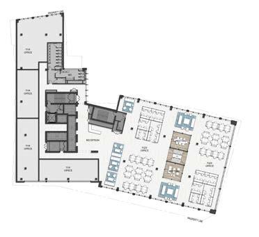
Level 10 | Events Space
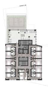
The events space continues with a series of multi-purpose rooms that extends out to a roof terrace. This space functions as banqueting, meeting and shared events space associated with the hotel.
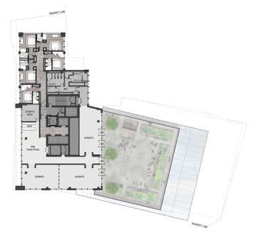
Levels 12 – 25 | Hotel
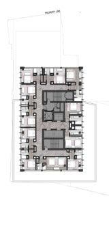
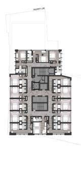
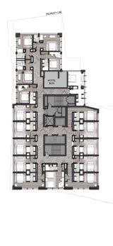
The hotel, with guest rooms on intersecting volumes that encourage openness and maximise views. A fitness centre for hotel guests is located on level 13, with an outdoor terrace for meditation, yoga, group or individual sessions.
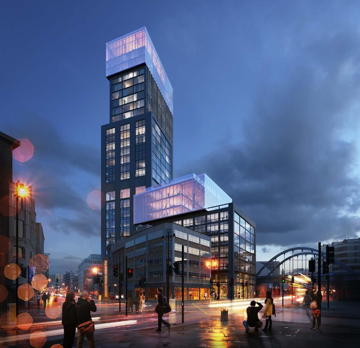
DESIGN,
THE EVENTS SPACE - LEVEL 10 HOTEL - LEVEL 12 HOTEL - LEVEL 13 HOTEL - LEVELS 14 - 18 HOTEL - LEVELS 19 - 25
FINAL
LEVELS
Levels 26 – 29 | Sky Lounge
Special guest rooms are located on levels 26 and 27. The spatial quality of these rooms will be enhanced, with maximised views. The Sky Lounge on level 28 will be a small and intimate space, its principal aspect being to deliver panoramic views orientated mainly to the west, south and east, capturing outstanding London views.
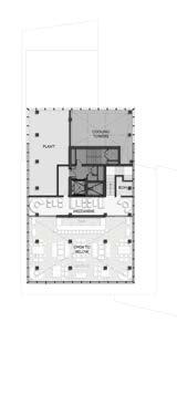
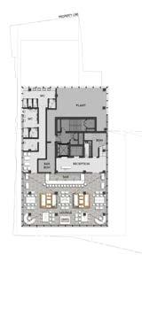
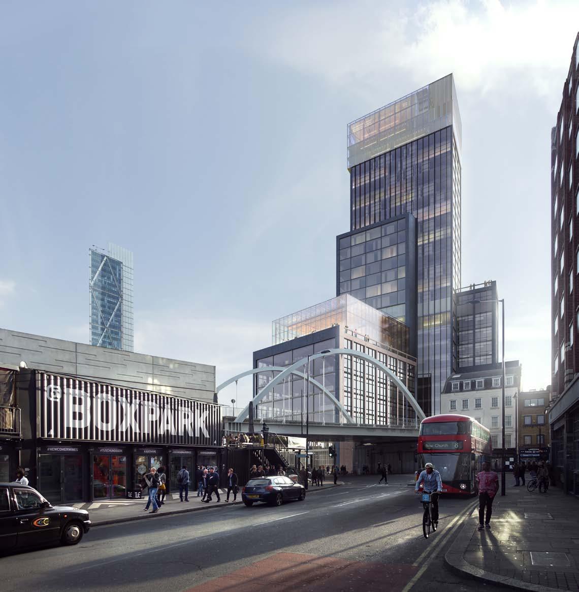
HOTEL - LEVEL 26 HOTEL - LEVEL 27 'SKY LOUNGE' - LEVEL 28 'SKY LOUNGE' - LEVEL 29
FINAL DESIGN, LEVELS

Perspective Section
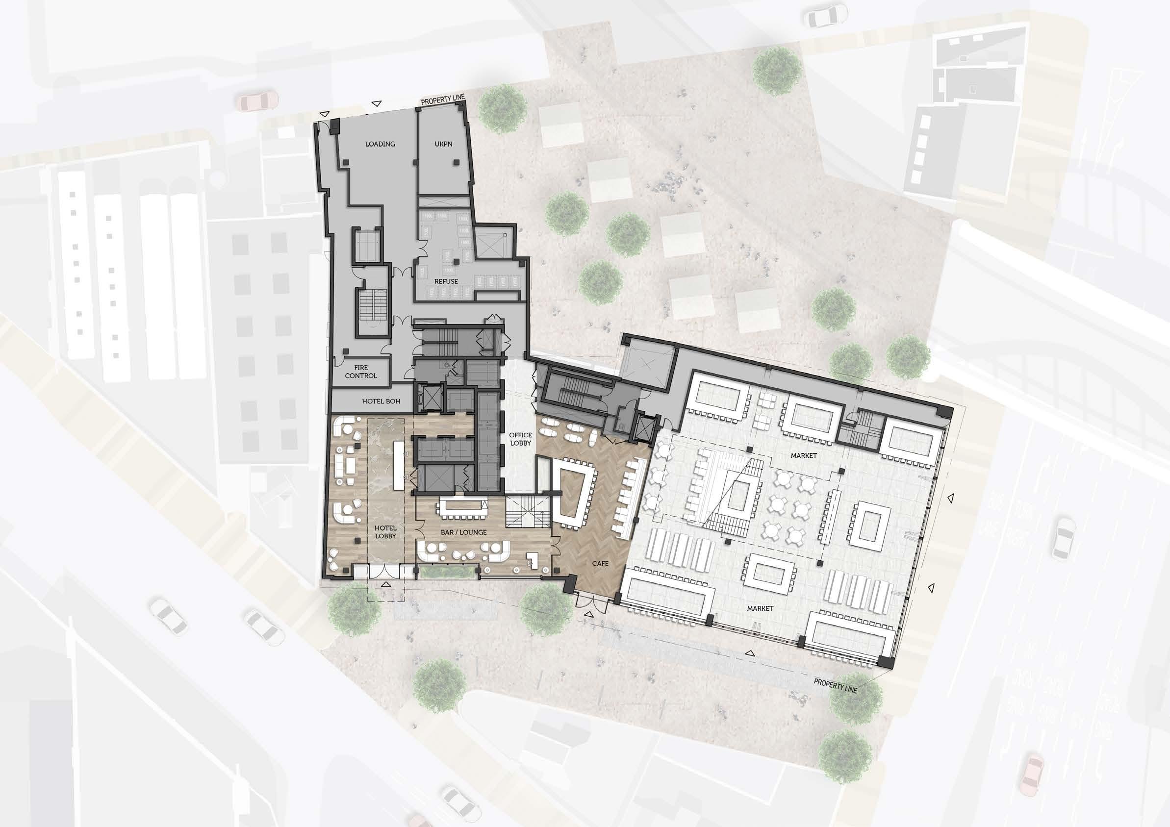
Ground Floor Plan


EXTERNAL
EWS D1REFER TO SHEET A2.404 EWS A KEY 03 AR2-401 A Facade Detail Sheet
SCALE: 01 PART PLAN - EXTERNAL WALL TYPE A 1:50 SCALE: 02 EXTERNAL WALL TYPE A 1:50 SCALE: 04 PART SECTION -
WALL TYPE A 1:50
EWS DREFER TO SHEET A2.404 EWS B 01 PART PLAN - EXTERNAL WALL TYPE B 1:50 02 EXTERNAL WALL TYPE B 1:50 04 PART SECTION - EXTERNAL WALL TYPE B 1:50 AR2-402 A Facade Detail Sheet
Site location
Height heat map analysis Buildings in Shoreditch and City of London
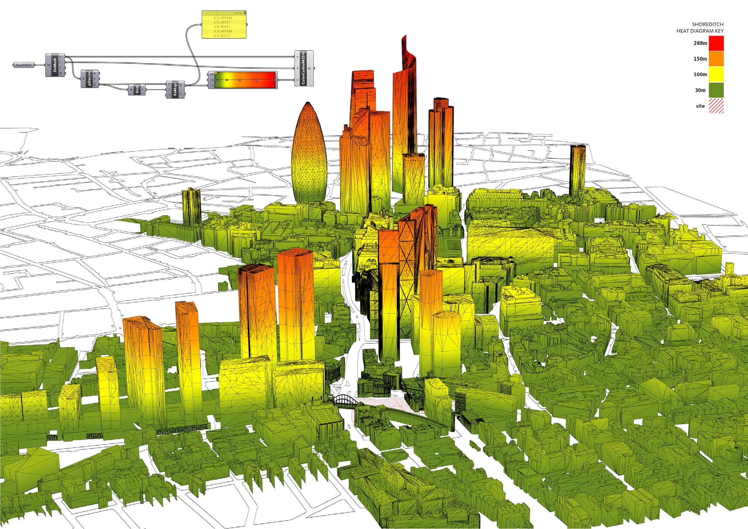
CONSENTED VIEWS
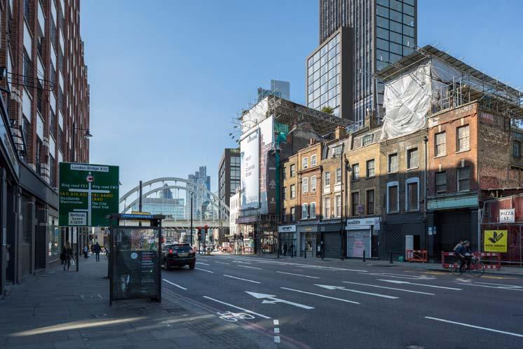
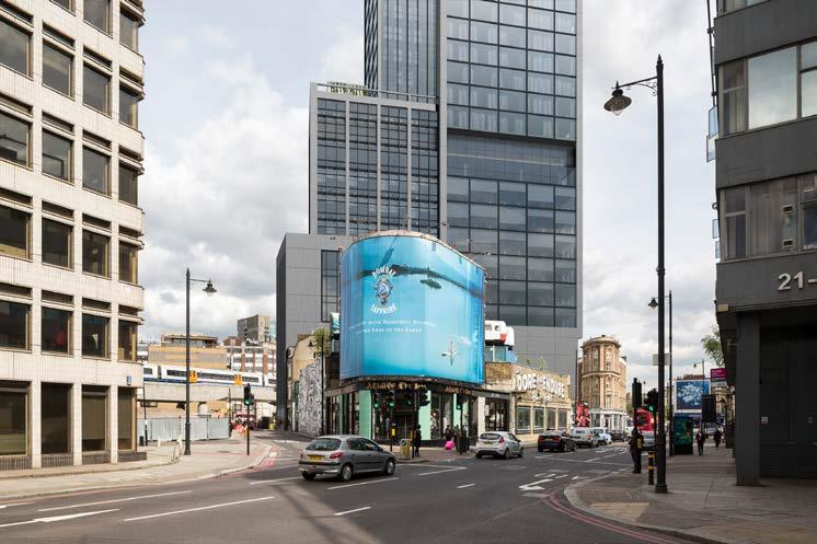
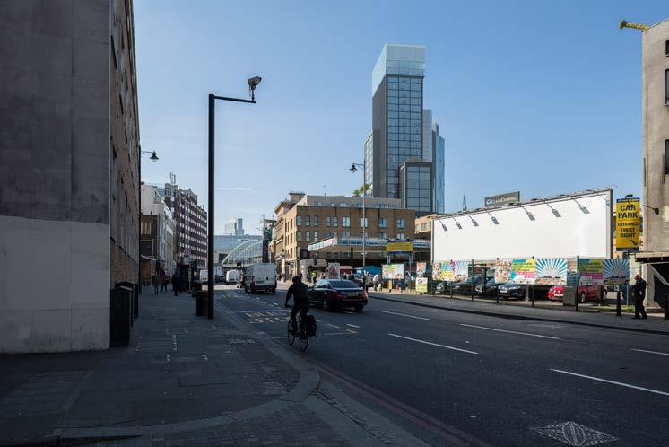
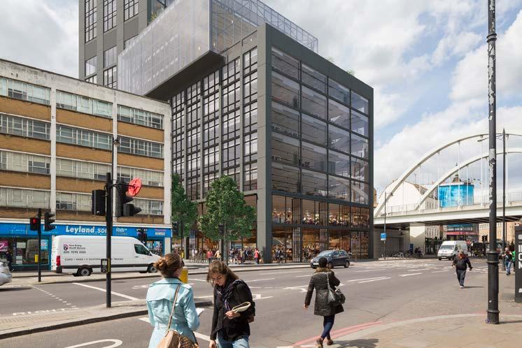
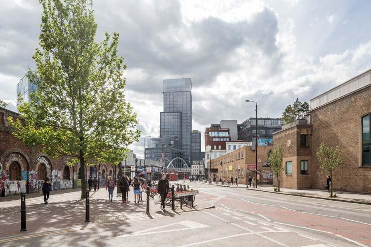
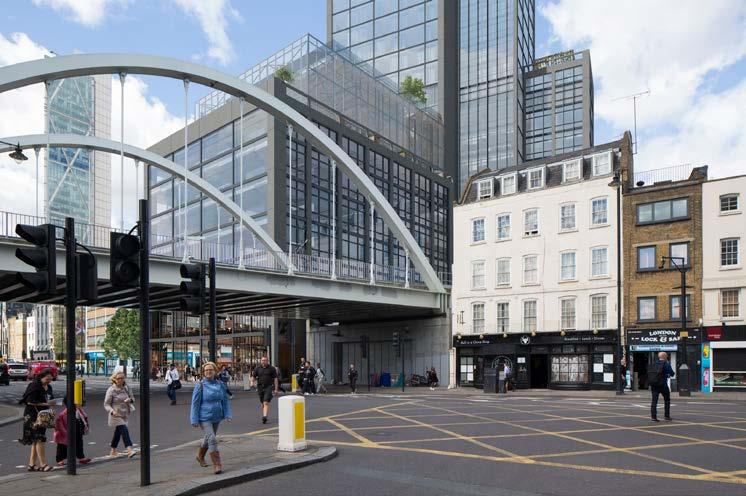
CONSENTED VIEWS
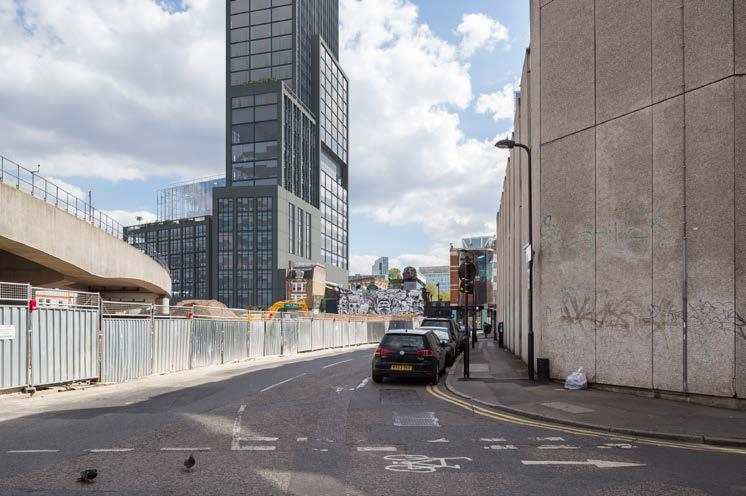
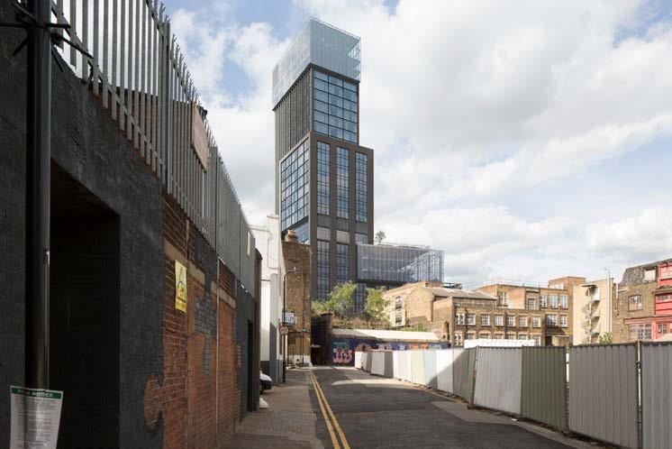
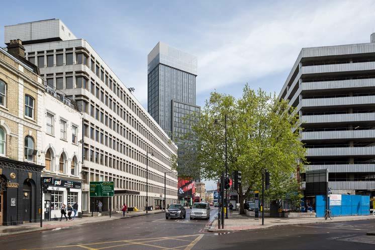
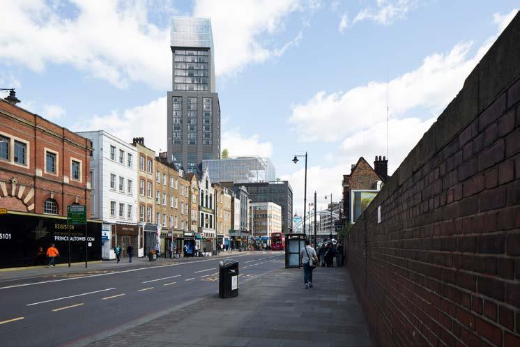
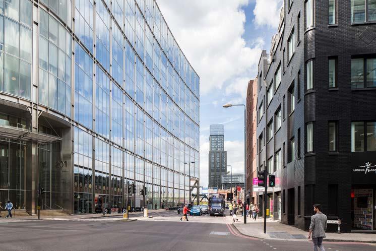
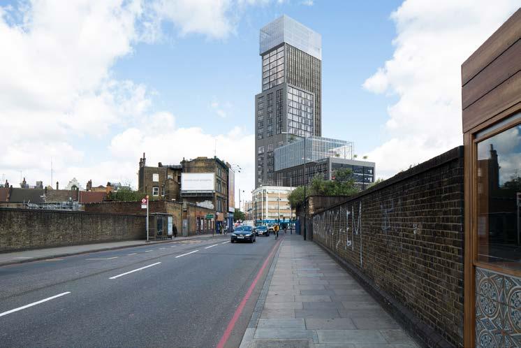
PREVIOUS PROJECTS
Reebok Concept Store
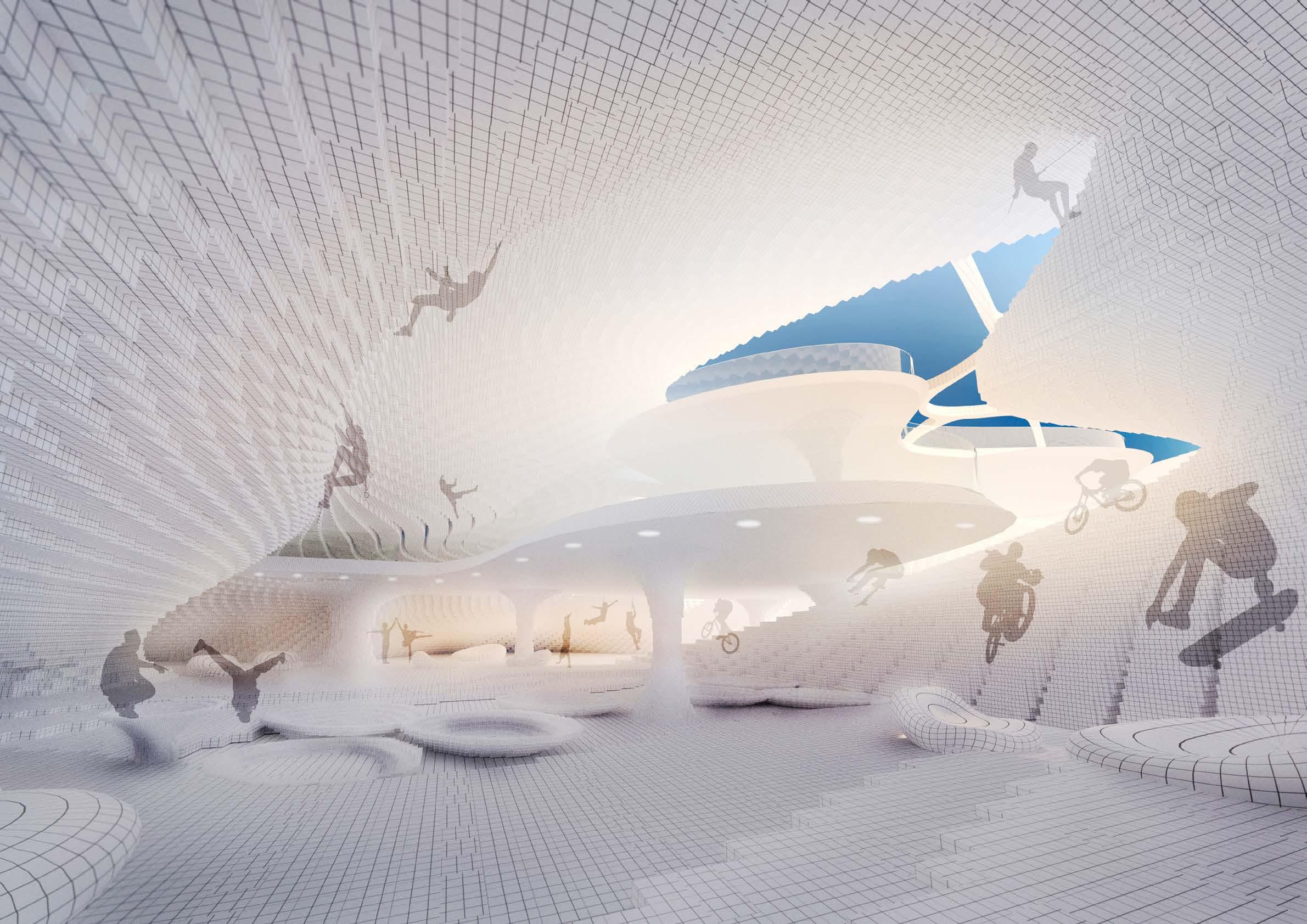
Master Thesis 2013
Internet is changing the retail experience, and how we shop. The role of the storefront is changing. It may not be devoted to physical sale anymore. The currency of value would be the experience. Designing these shopping experiences is about creating opportunities to facilitate impulse purchases. According to paradoxof choice: too much choice results in confusion and indecision. The perceived value of product must come from the user experience. Reebok Concept Store is an attempt to create a sport equipment retail place combined with product fabrication area and space for active entertainment to test the products on the site. In this thesis Computer Aided Design, Voxel Space, Additive Fabrication, Computer Aided Manufacturing, product customization technology, body scan, and the specification of fabrication process in architectural scale were applied in t he design process to achieve a final result – the Concept Store dedicated to sport. The result indicates that this way of performing the design process enables more discussions on high level design issues, supports more effective design operations and creates new field for architectural expression. This thesis suggests that designers can benefit from the use of objects in voxel-based design environments.
Second Award in the International Architectural Thesis Award 2013 *
*
To promote activities happening in the store, the building is situated in the ‘passive’ type of space - one of the biggest shopping mall parking outside Warsaw, Poland. People living in the city orientate with the use of the Cartesian space. People living among nature have spatial intuition and orientation in relation to objects and localities and perceive the space as a web of paths (Nomads). An organic shape of the building was designed to imitate sport tracks but also to stimulate the users’ sense of orientation.
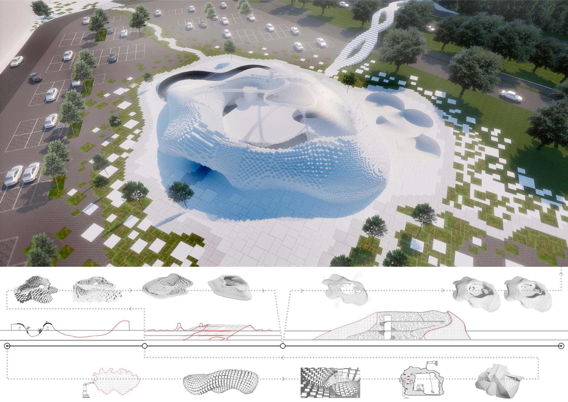
MARCH 2013
COMMUNICATIVE MOMENT
CREATIVE MOMENT
DESIGN PROCESS
STRUCTURING MOMENT
The architecture of the store is created in voxel-based design environment. Voxel is a space unit to which different materials and resolution can be assigned. This environment combined with fabrication technology enables the creation of shapes which were difficult to build before. The building construction process is similar to 3d printing, which already is widely used for product fabrication. Sport equipment exhibition is designed in the wall. This intervention incorporates user experience with the purchasing process. Clients are invited to explore the store’s space and find new equipment ‘hidden’ on many levels. The store’s structure works as a diagnostic station where clients’ movements are scanned and diagnosed. This information is later needed for producing customized, personalized sport equipment in the store. Before purchasing the client has a great opportunity to test the products.
Typical for Poland sun angle has direct impact on the building’s shape. The slope for winter sports is situated on the North side of the building letting the snow last longer.
differentiated resolution of the building structure allows intelligent distribution of material properties which contributes big savings it can also be used for creating various sport tracks

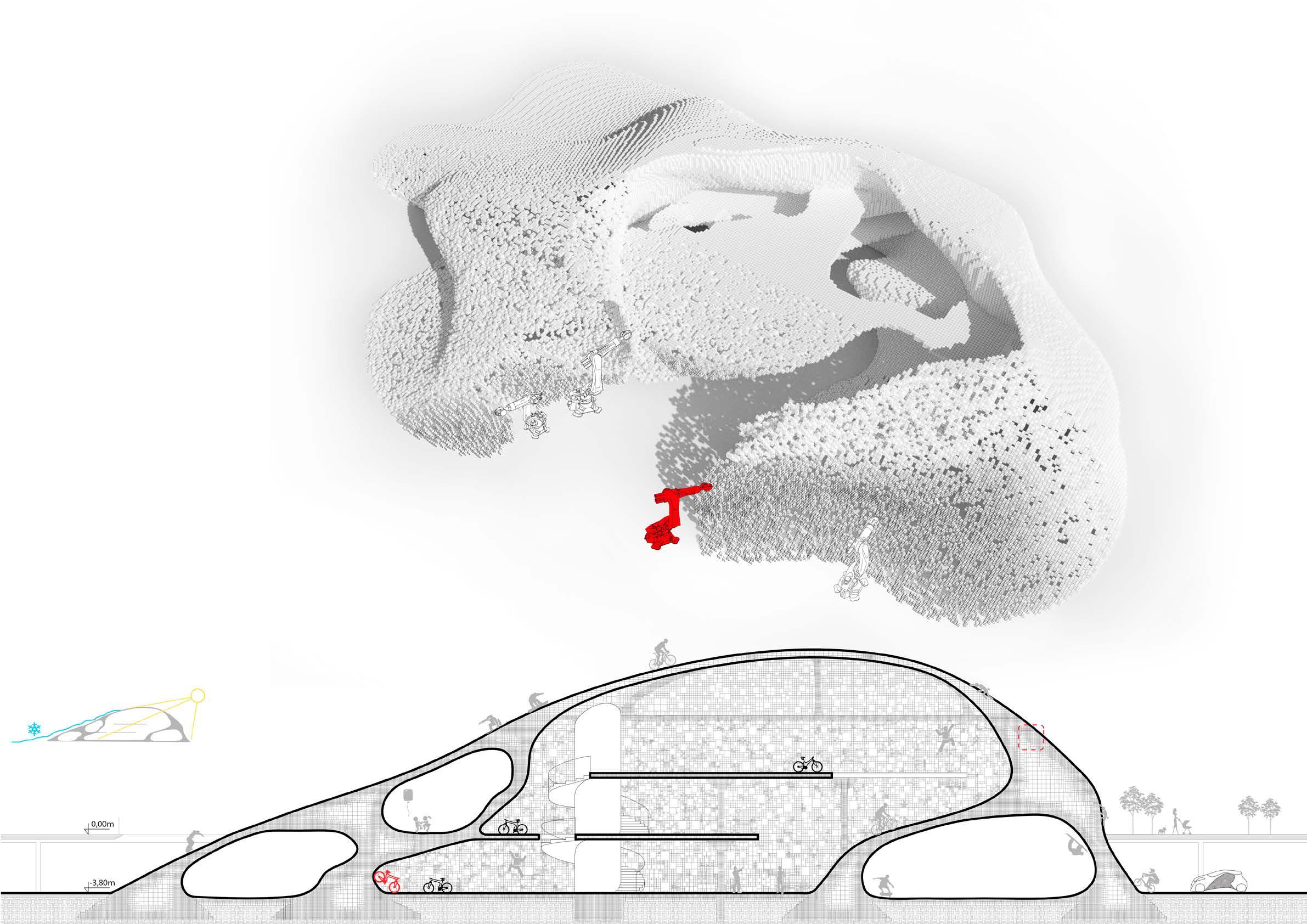
The web of paths, the organic floor plans and the outside and inside slopes create a very dynamic space which is tested by the users. Walls inside the building act as rock. Different resolutions of the wall material create diverse environments for the sportsmen.
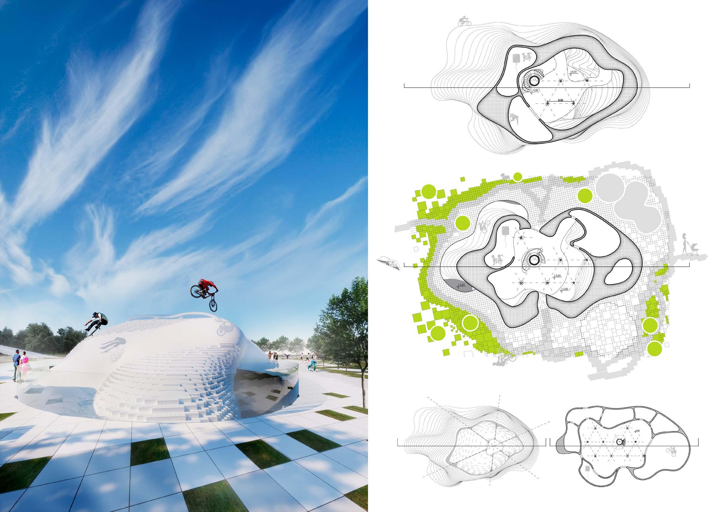 FIRST FLOOR PLAN
UNDERGROUND FLOOR PLAN ROOF PLAN
GROUND FLOOR PLAN
Barge Restaurant
on the Vistula river 2013
The restaurant was designed on the occasion of the football tournament, Euro 2012, organised in Poland and Ukraine.
The restaurant is built on a floating barge on the river and it is connected with the pedestrian bridge.
The restaurant’s 2nd level space is being customized by the designed conveyor system. It forecasts the number and density of the tables needed for an exact event.
The restaurant also has a smart roof which reacts to the sunlight. Kinetic modules open or close depending on the weather and conditions inside the restaurant.
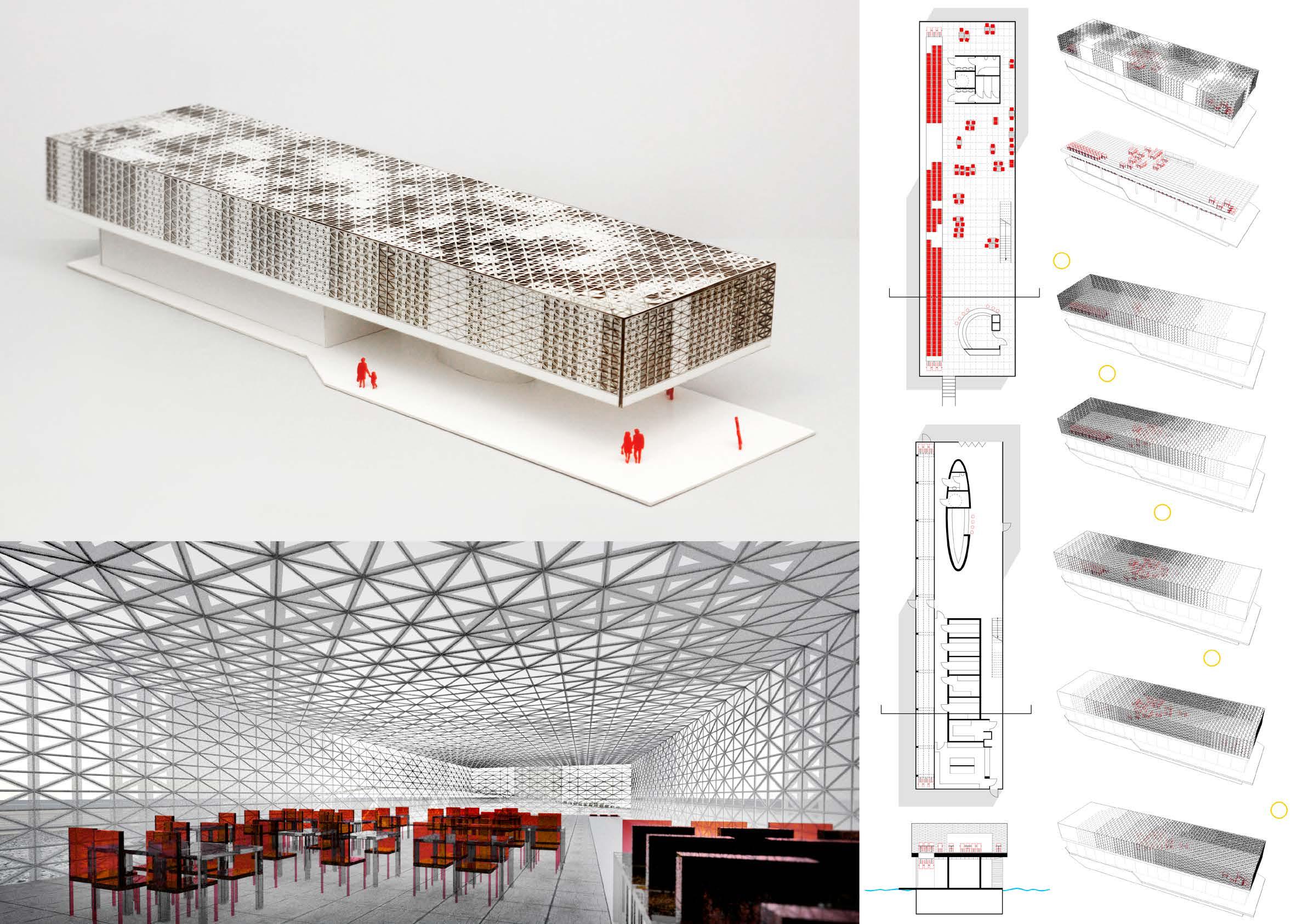
CityOlsztyn Square Competition
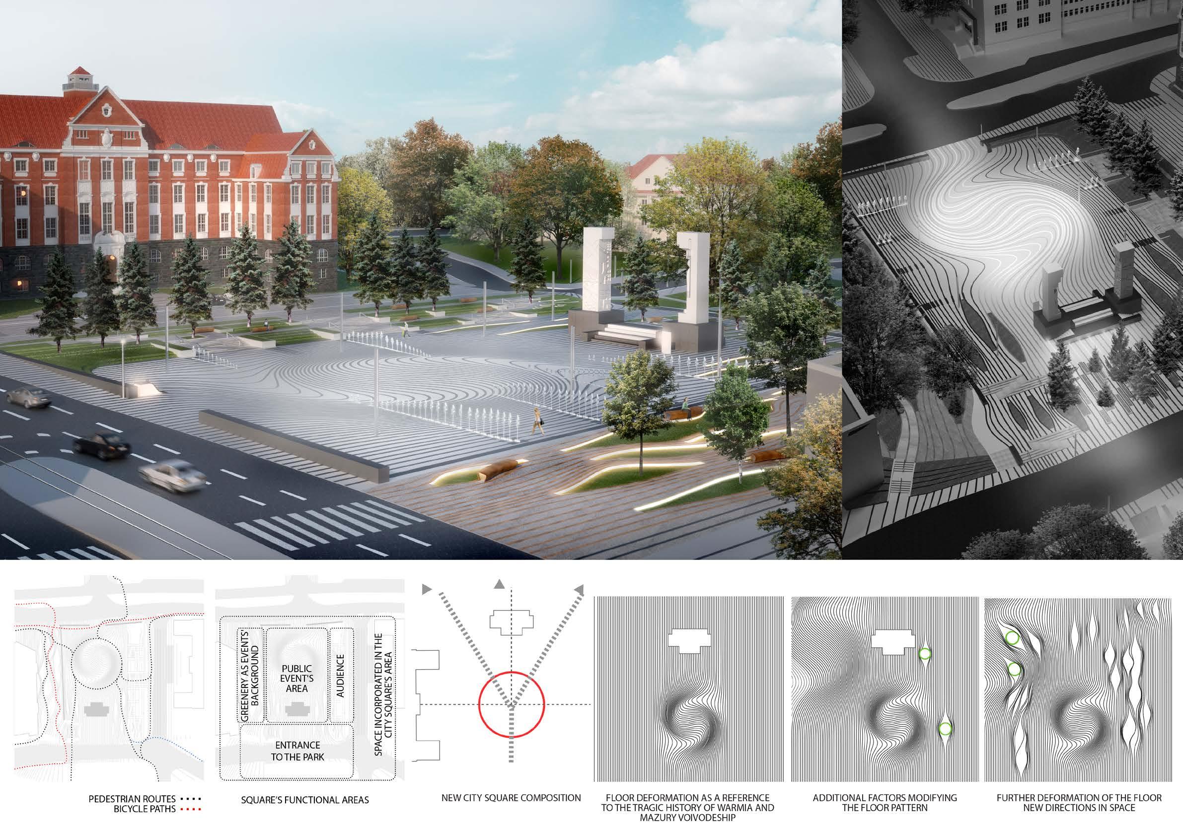
2013
The most important element of the city square is a monument created by Xavery Dunikowski. The square design idea was to emphasize the monument’s importance. Lines on the floor indicate the time and tragic events which occured in this area. The floor pattern deformation is designed in such way so that main space axis have been kept. The computer script developed during the design process enabled the designers to manipulate the deformation of the linear patterns and to create a new composition of the square.
Second Award * *
Robotic Canopy

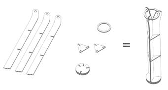
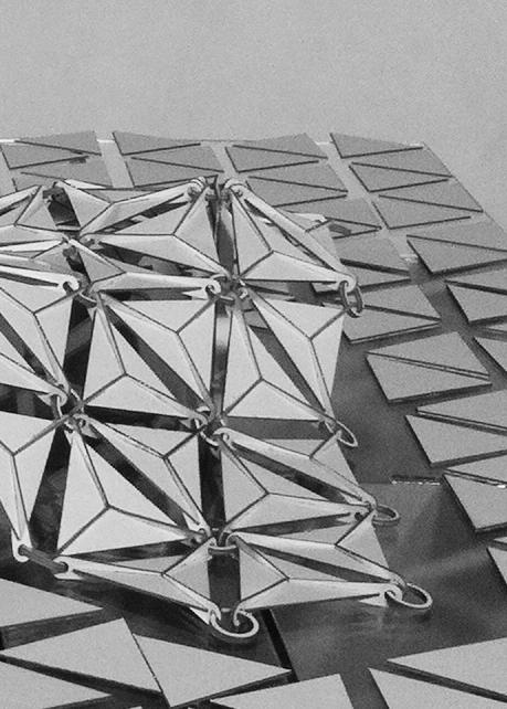
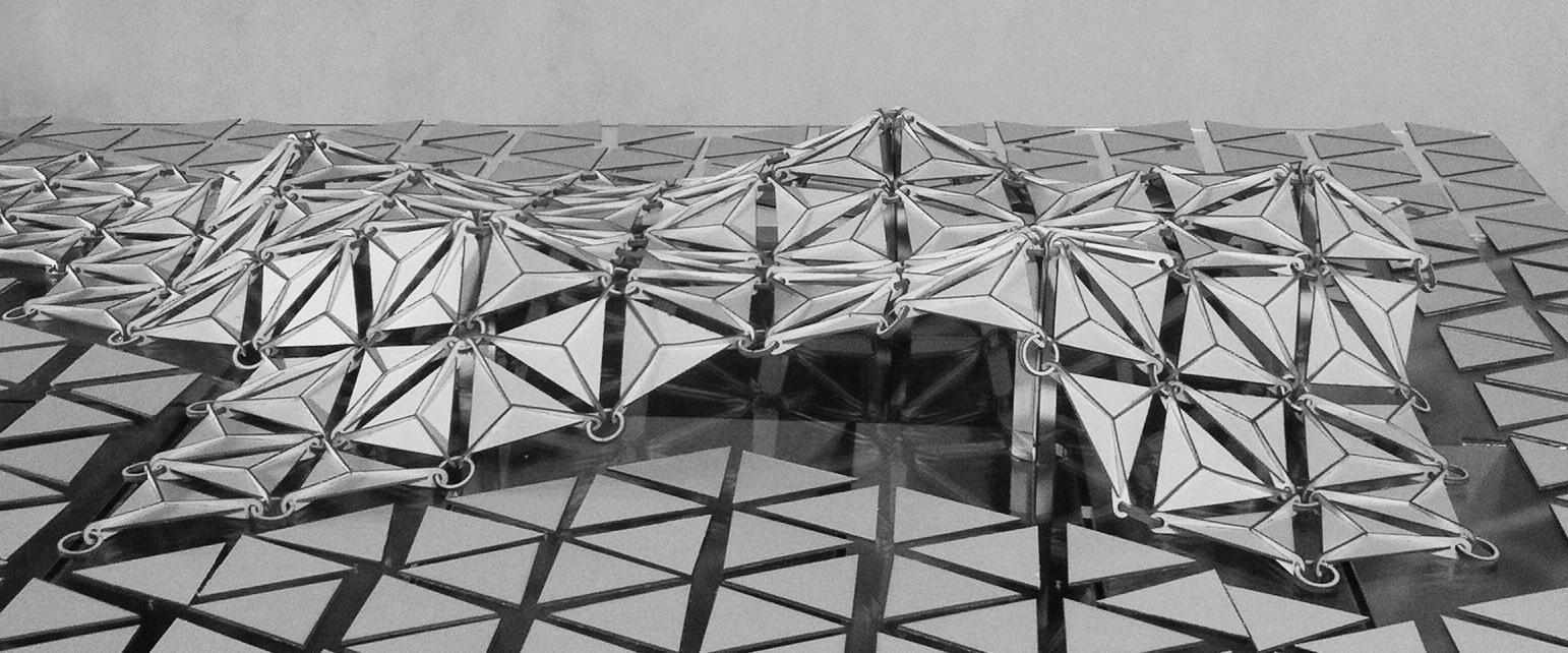
2012
The project combines the kinetic and performative aspects of design with basics of robotics to create conceptual construction of responsive environments.
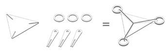
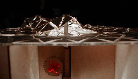
It is a modular tessellated geometry that may be adopted to different city plots. The whole structure is supported by servo motors driven columns. Several alternative sequences of movement are provided in the prototype model. The mechanism is controlled by Arduino programmable controller.

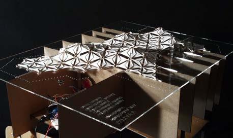
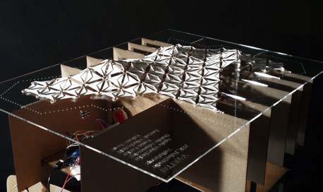
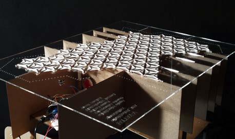

Coworking Building
Madrid
Competition 2011
The Hive is a platform that encourages people to meet and establish a potential future collaboration. The Hive is a place where one can choose the people to work with. It is a collaboration catalyst.
All freelancers are welcome to the public space, where they socialize with others and after some time they can choose to collaborate. They can become members of a specific group or create a new group and thus extract a work region for themselves inside the building. This region can extend in time, forming a larger group by accepting more members.
Additional layers of honeycomb structure are added when more area is needed. If the number of coworkers decreases in the future, some parts of the building can be disassembled, decreasing the maintainance costs.
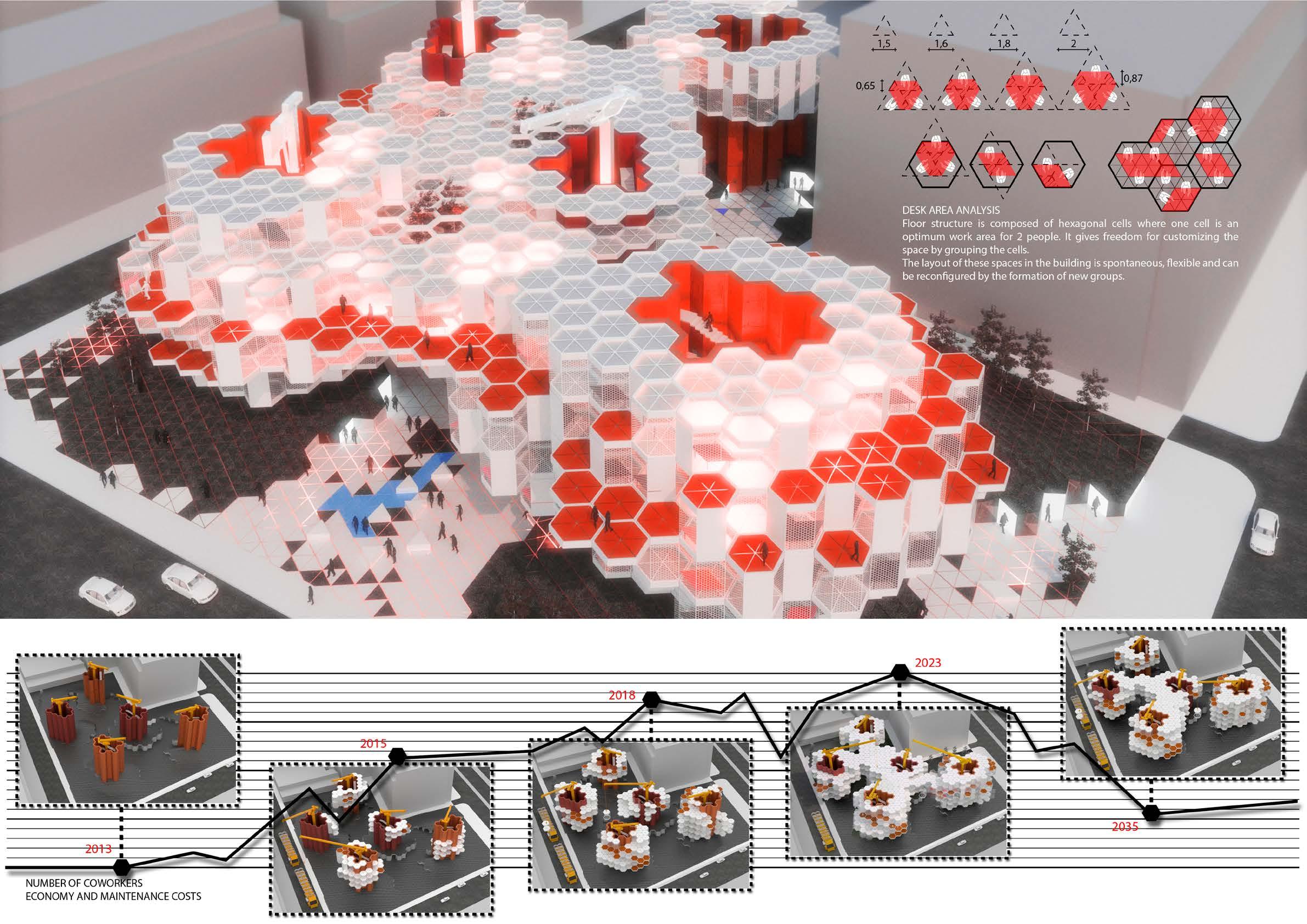
Second Award * *
Parametric Bench
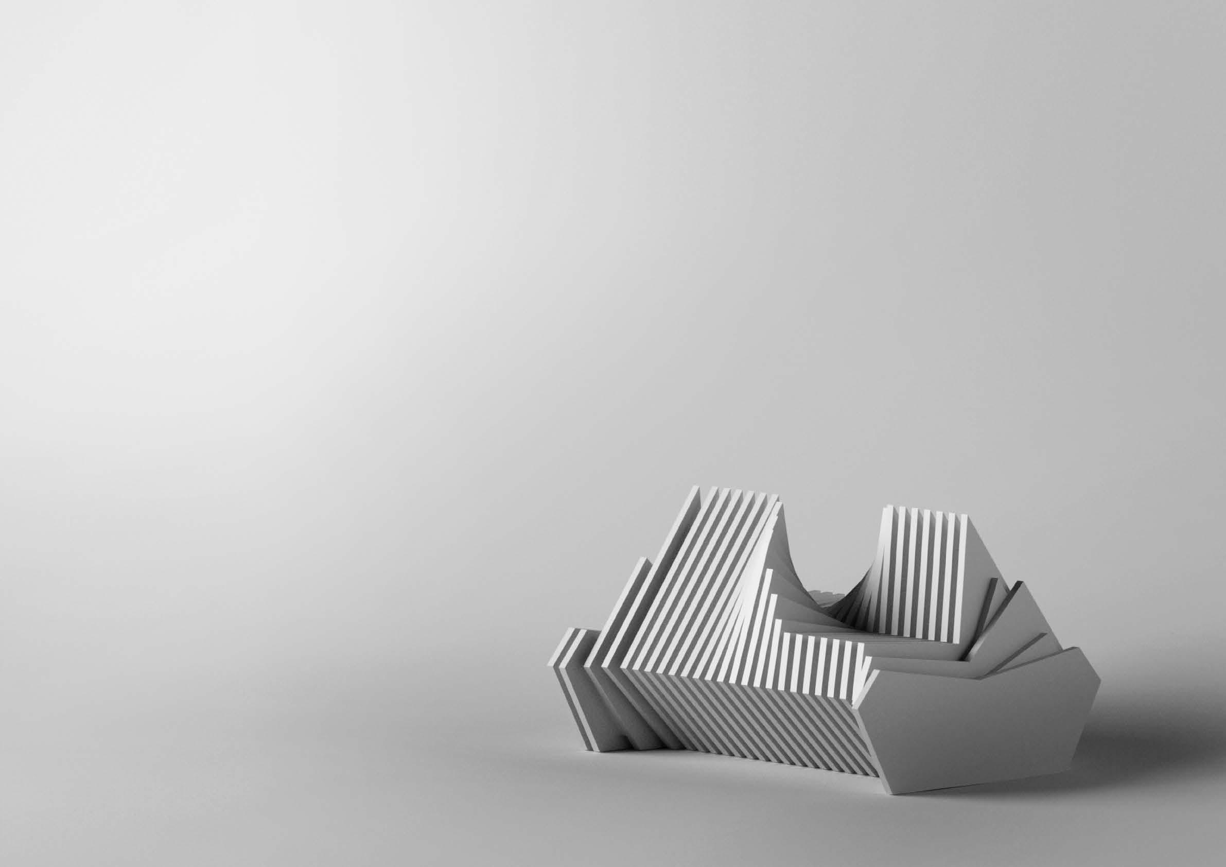
2009
The aim was to explore the potentials of a fully integrated design process which incorporates digital techniques from very early stage starting with the use of programming and scripting (in Rhino Monkey) as design strategy leading to digital fabrication as the construction technique. For the bench fabrication styrofoam panels cut in the thermal plotter were used. The final prototype was created in scale 1:1. The bench is suitable for two people. Its elements rotate around a common axis creating two opposite seats so that users while sitting can talk face to face.
a/ 2a /2 a a a - main input - specific proportion of the user’s height additional input - width of the user’s loins
a/ 2 2a/ 3 a/ 3 a/ 3 a/ 3 a/ 3
a/ 6 a/ 3
90 degrees rotation of the elements
bench sections created from generative procedure
Kokon Lamp 2011
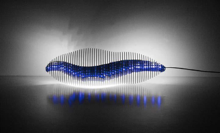
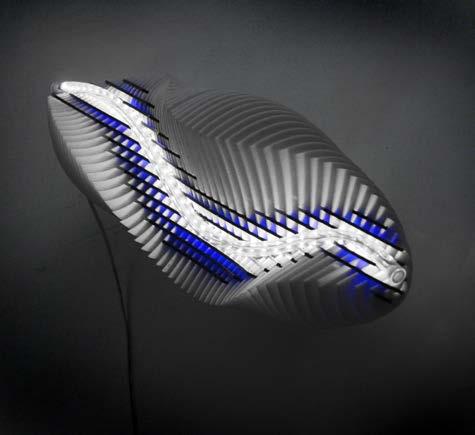
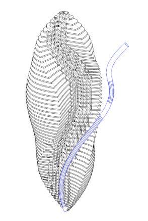
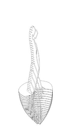
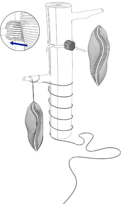
KOKON is a garden lamp. It was designed to manifest the importance of night insects to our environment. It uses low energy consuming LED light that does not give off ultraviolet light — unlike fluorescent and incandescent lights, which attract, trap and kill bugs. This lamp will not disturb evening pests while pollinating plants and maintaining gardens at night.
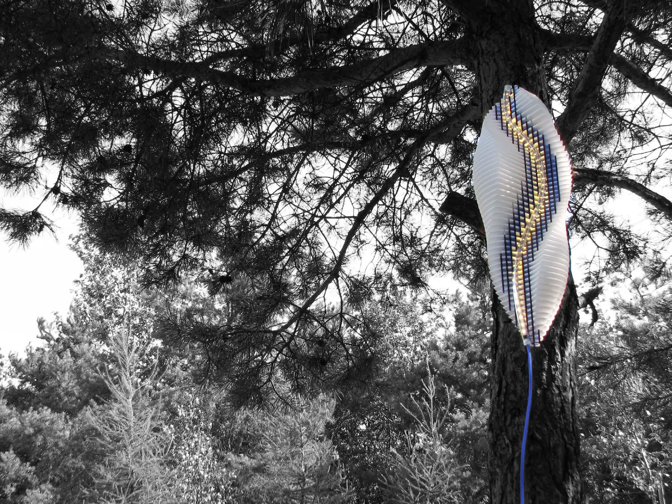
Made of natural materials Kokon lamp can become a part of the garden by letting it grow into the surrounding nature. Then its lighting function would be replaced and turned into shelter for insects.
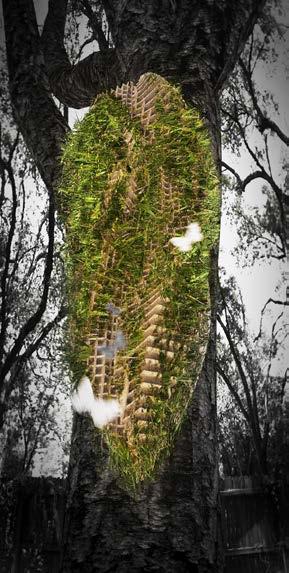
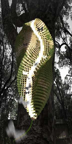
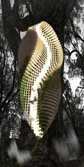
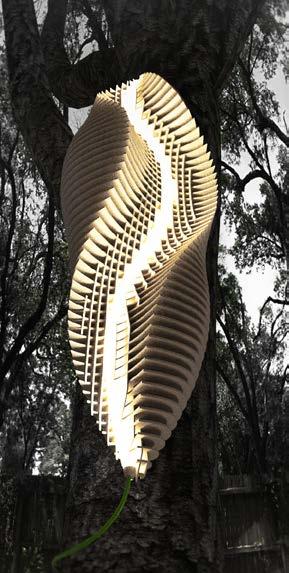
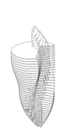
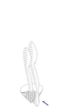
 BLUE ELEMENTS INDICATE THE LARVA IN THE FORM AND BRIGHT COLOR
TIME INFLUENCE ON THE WOODEN VERSION OF THE KOKON LAMP
BLUE ELEMENTS INDICATE THE LARVA IN THE FORM AND BRIGHT COLOR
TIME INFLUENCE ON THE WOODEN VERSION OF THE KOKON LAMP
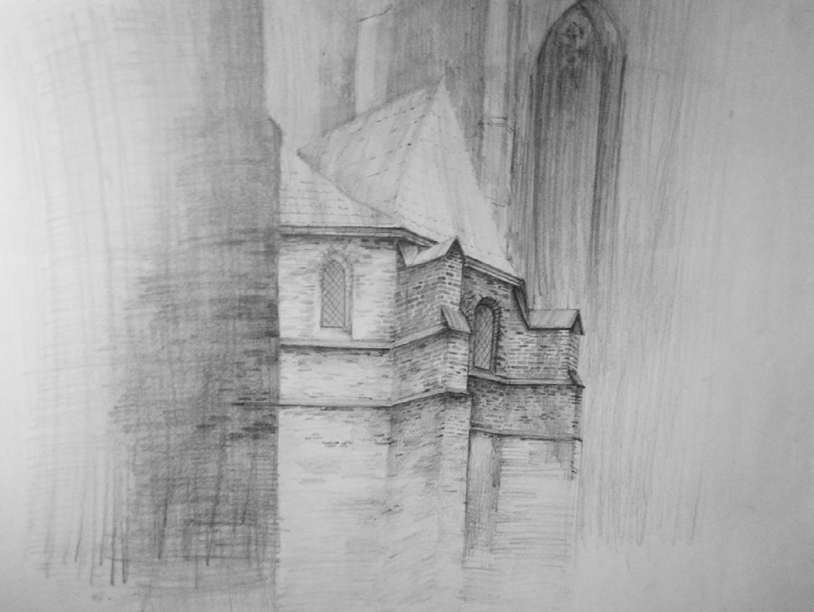
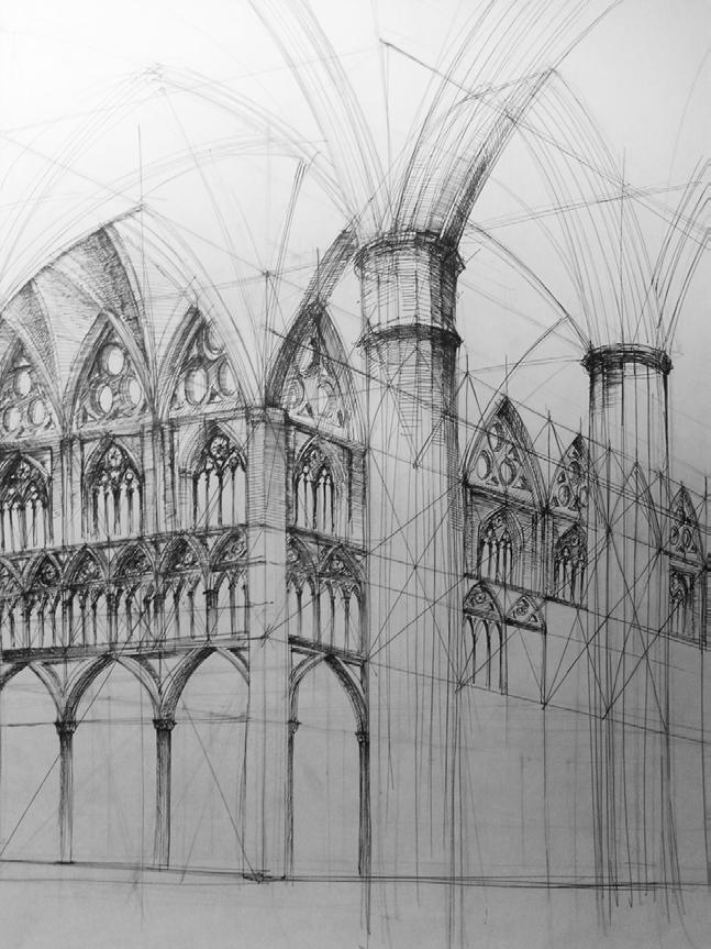
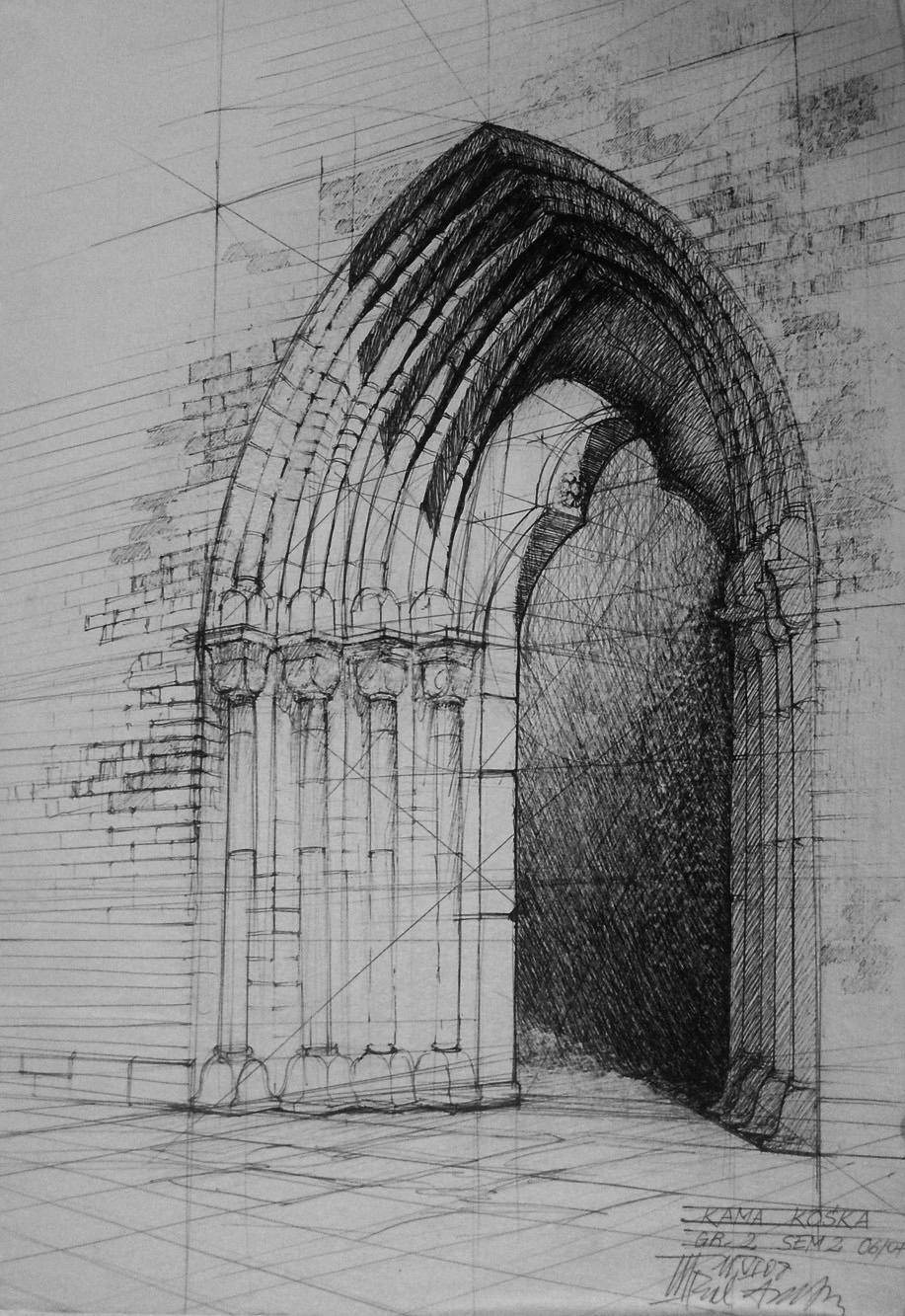
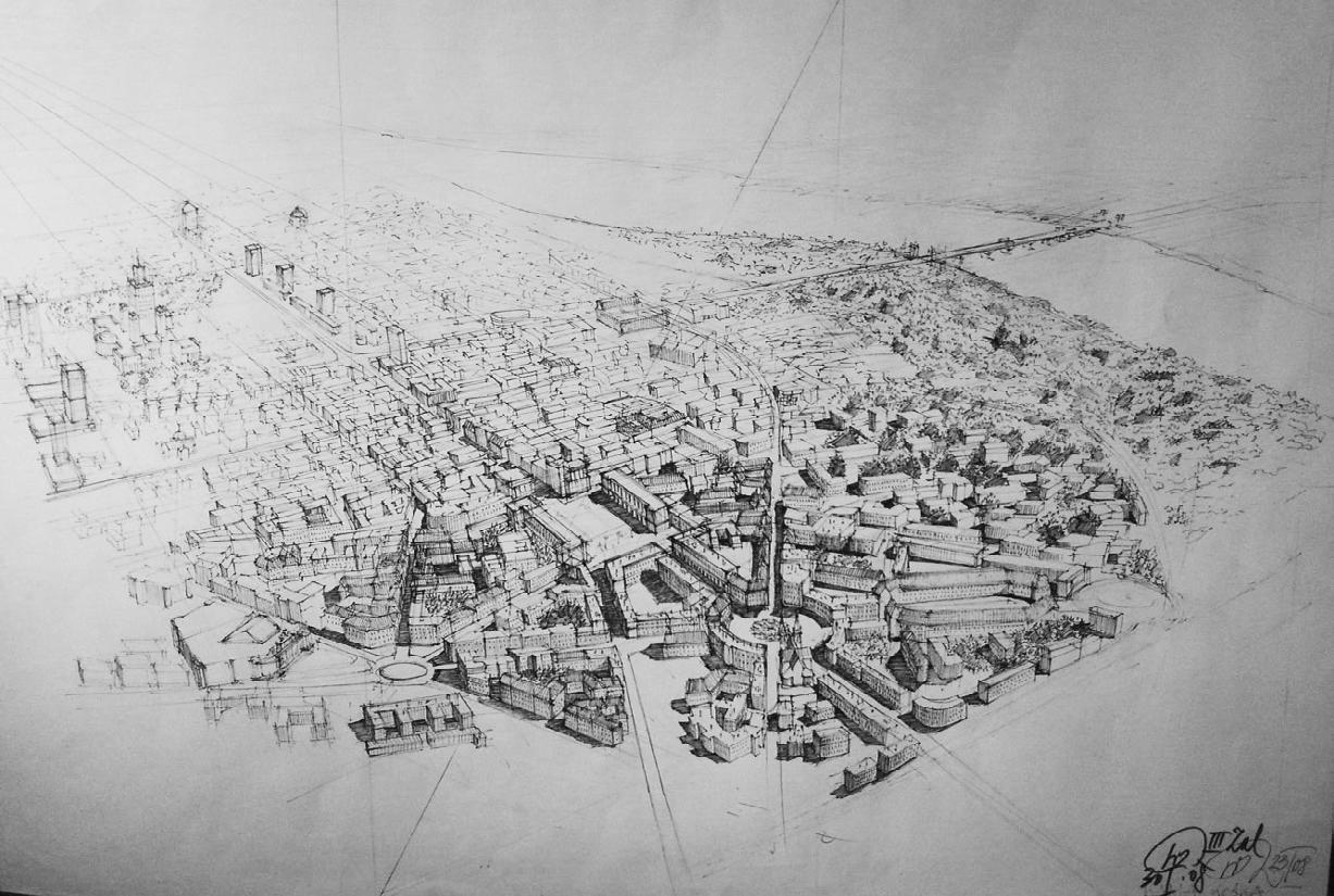
Thank you.