KALEY POLK
Portfolio
2018-2023
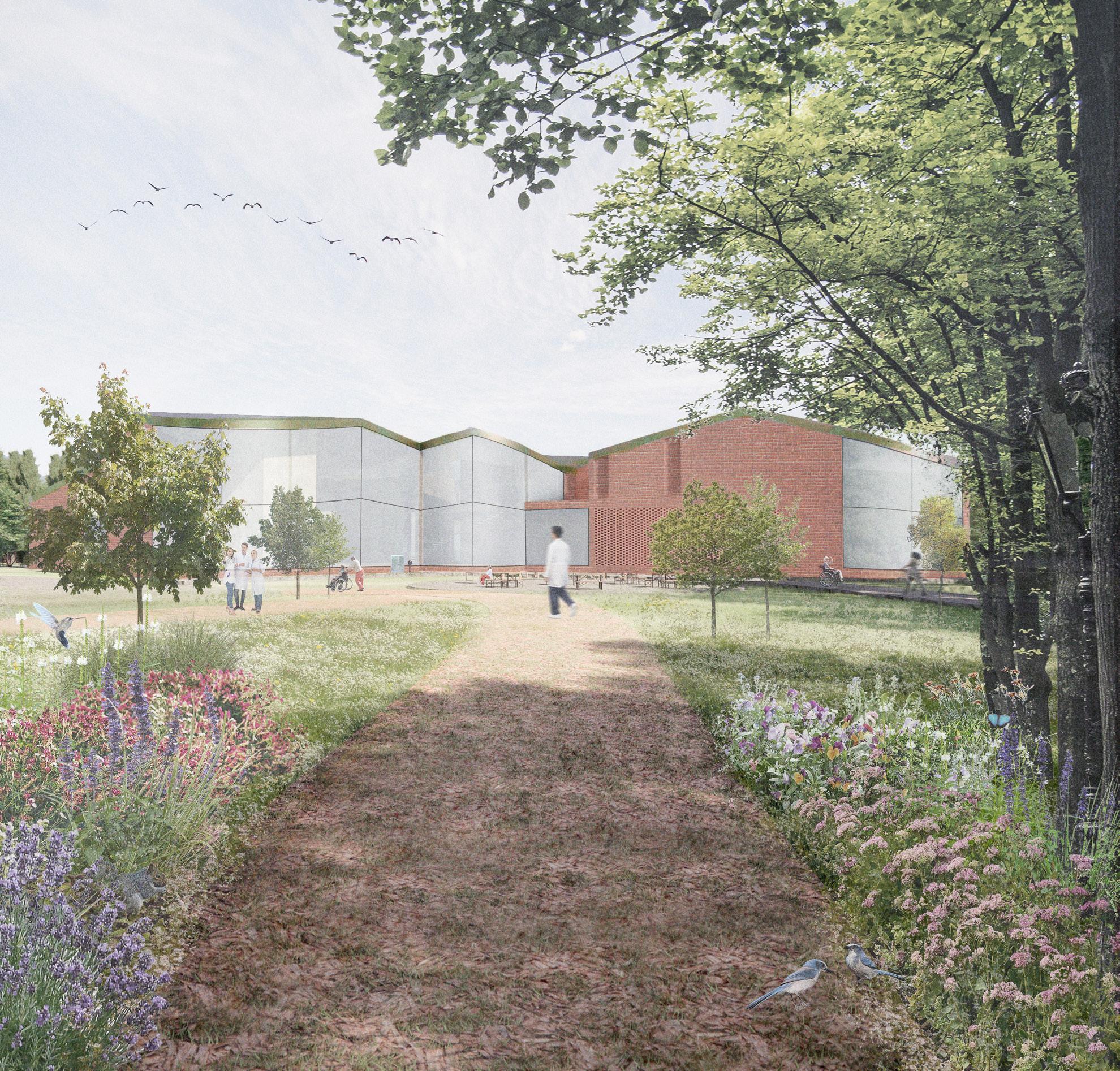
This advanced studio was centered around picking a medicial controversy and deeply researching it in order to imagine a speculative future and design an architectural intervention within that future. While working in a group with Gabi Gremillion and Aya Wen, we researched physician assisted suicide (P.A.S.) and envisioned a speculative future where P.A.S. could occur in speicific facilities focusing on mental health through all parts of the process. These facilities would act as a complex of different programmatic needs, offering medical and mental support services for not just the time before and during death, but also for the family after death. They also include other patient social services, such as lawyers, to allow the patient to access all of their necessary resources throughout the process in one location. We would be in contact with the patient from their first diagnosis, through all decisions and processes, and the family after the patient’s death. Our facility provides the mental support resources for those going through the process, and the physical resources to complete the process (either hospice or P.A.S.). With all of these components, we believe that this facility would function successfully within our speculative future and would better support the mental stress of many of the actors within the process, all while giving the patient more sovereignty and the freedom to choose how they die with dignity.
Boston, Massachusetts
Advanced Design Prof. Stephanie Choi
Partners: Aya Wen + Gabi Gremillion Design Excellence Winner Spring 2022
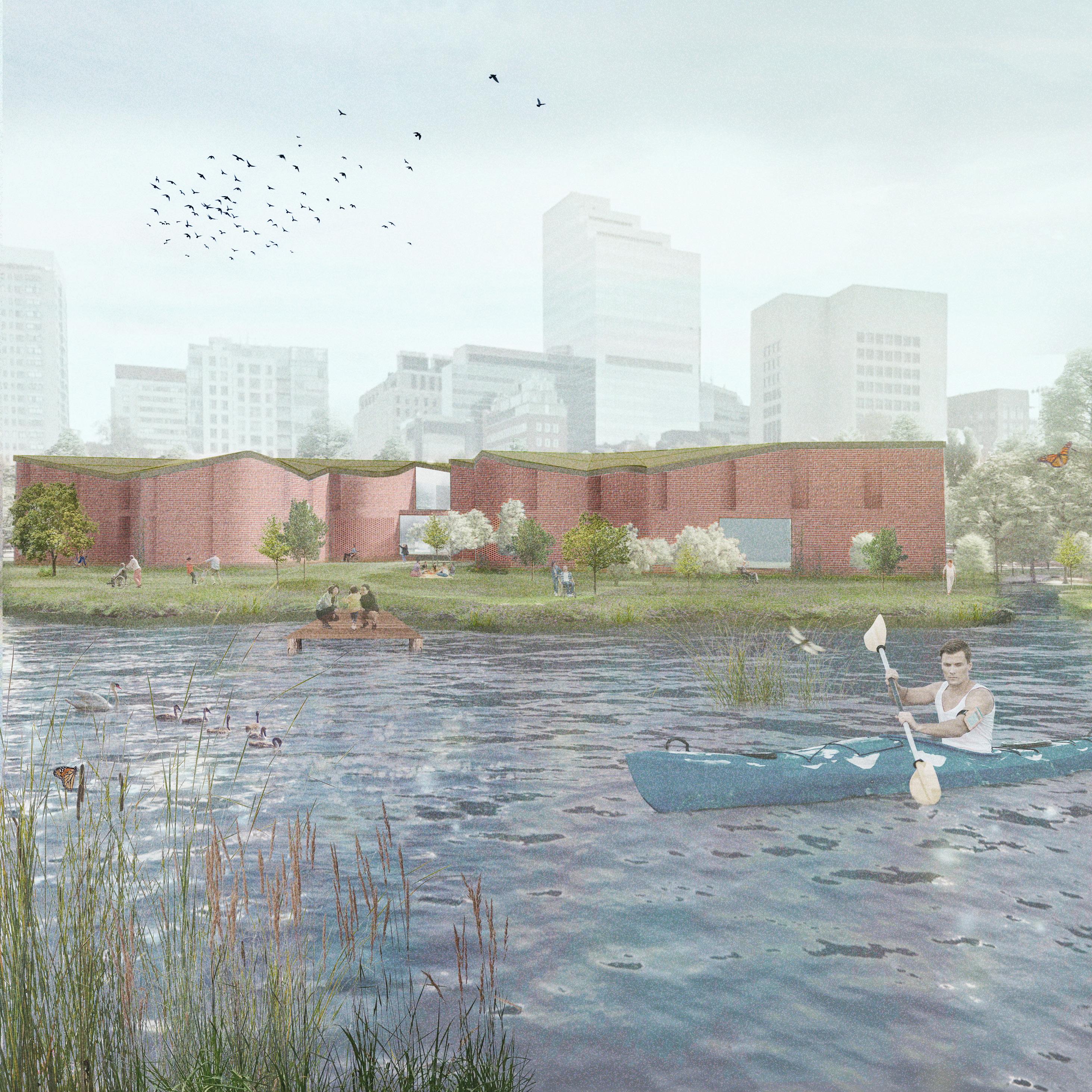
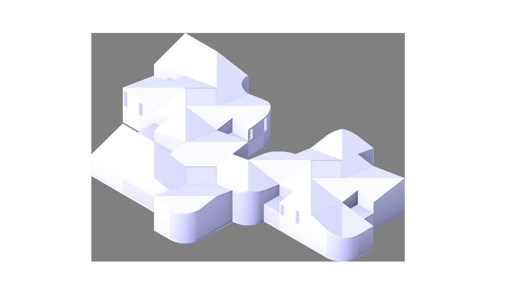


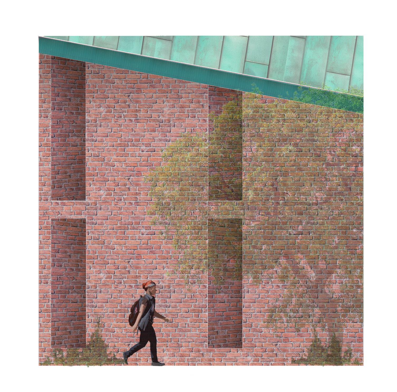

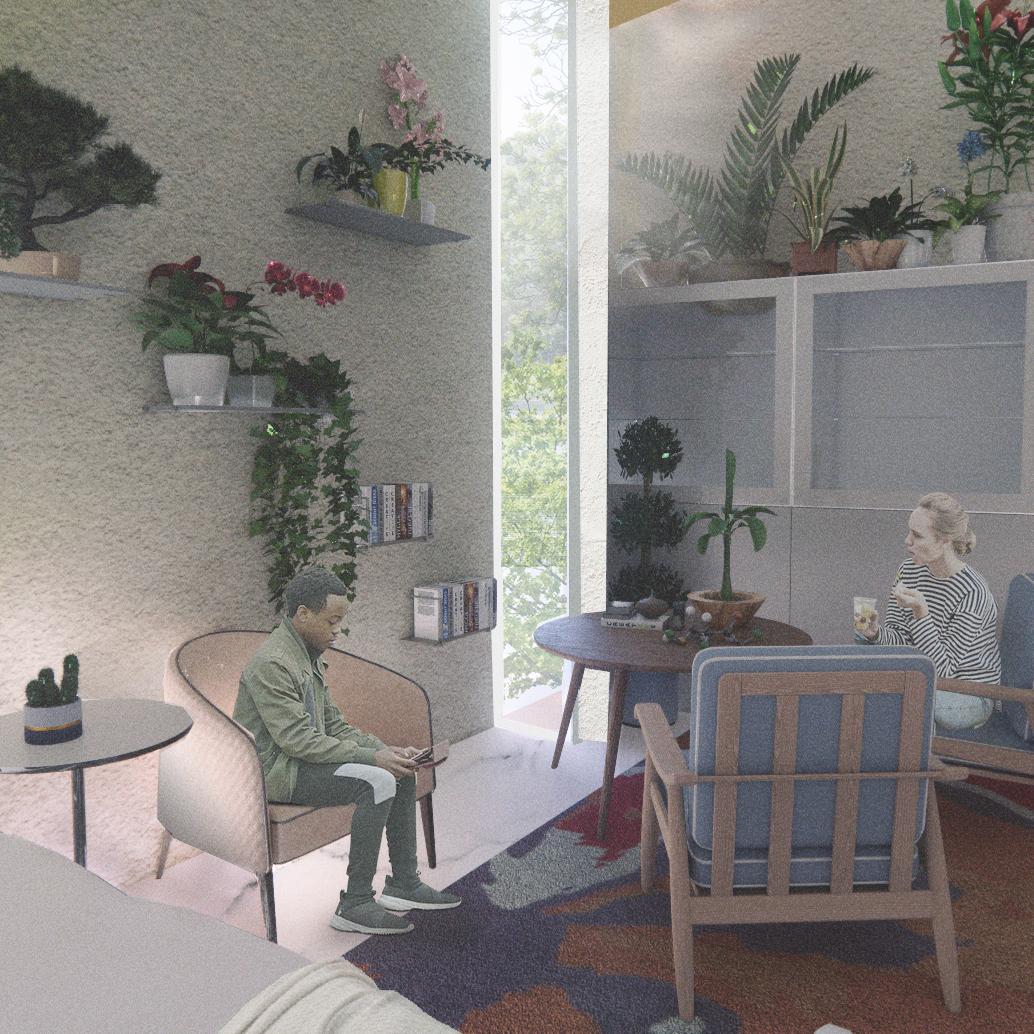
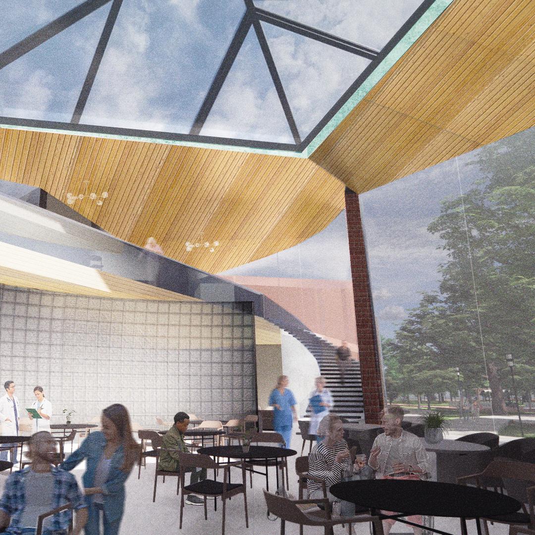
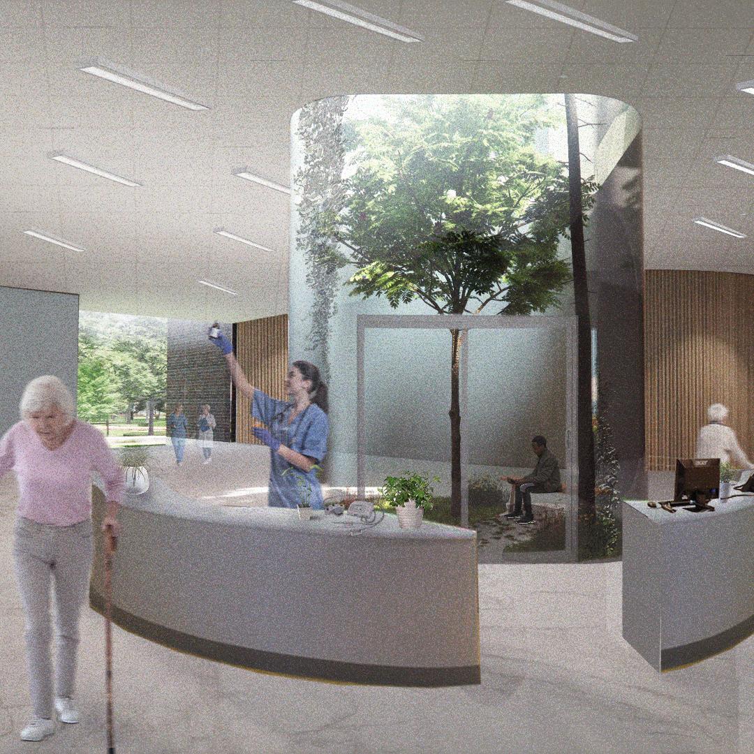
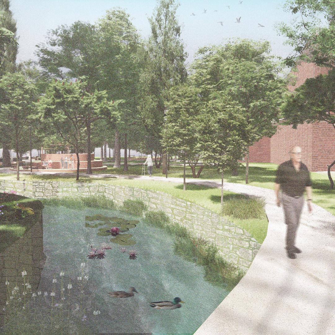
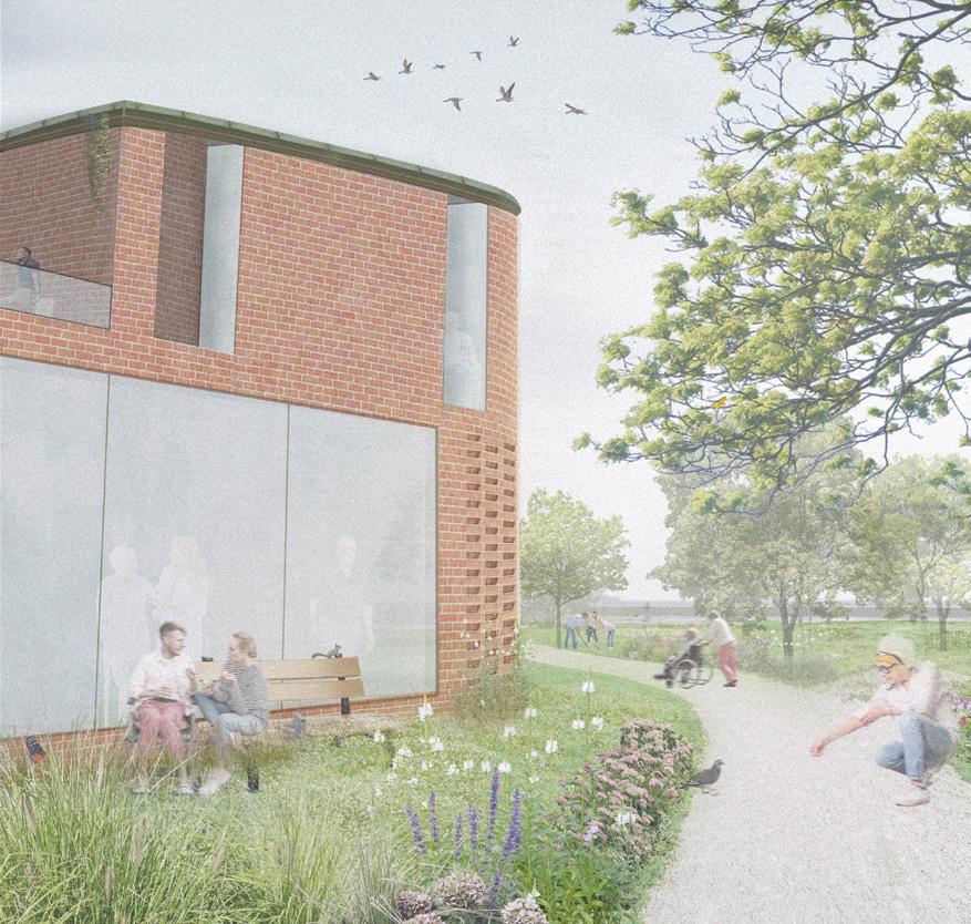
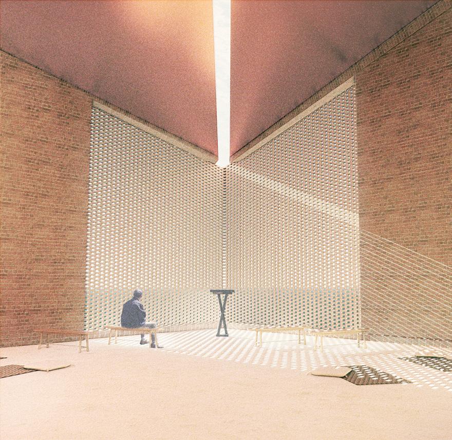
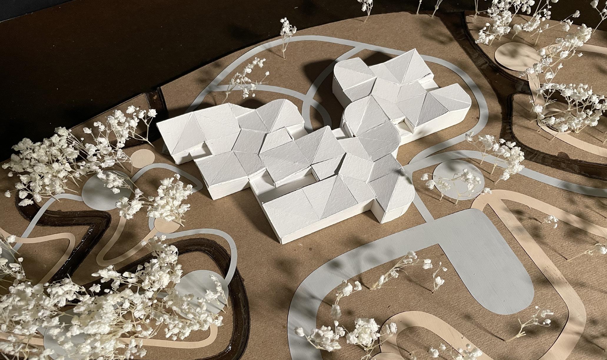
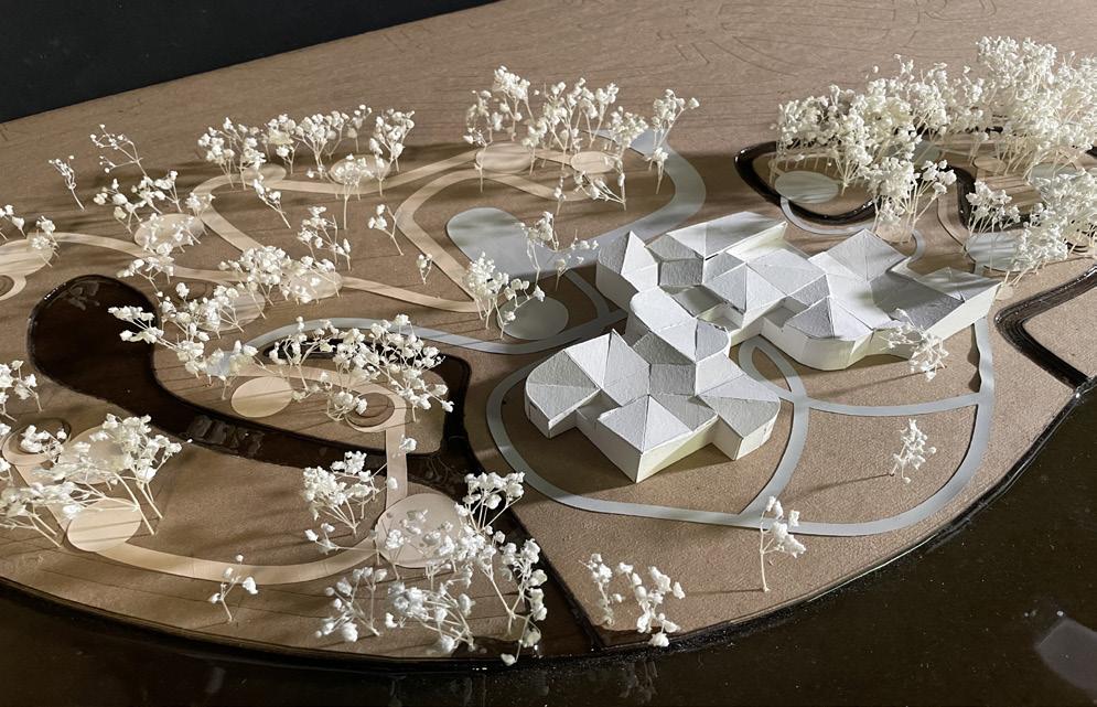
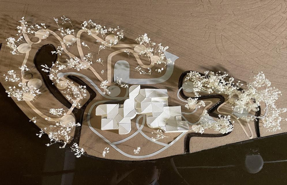
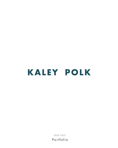
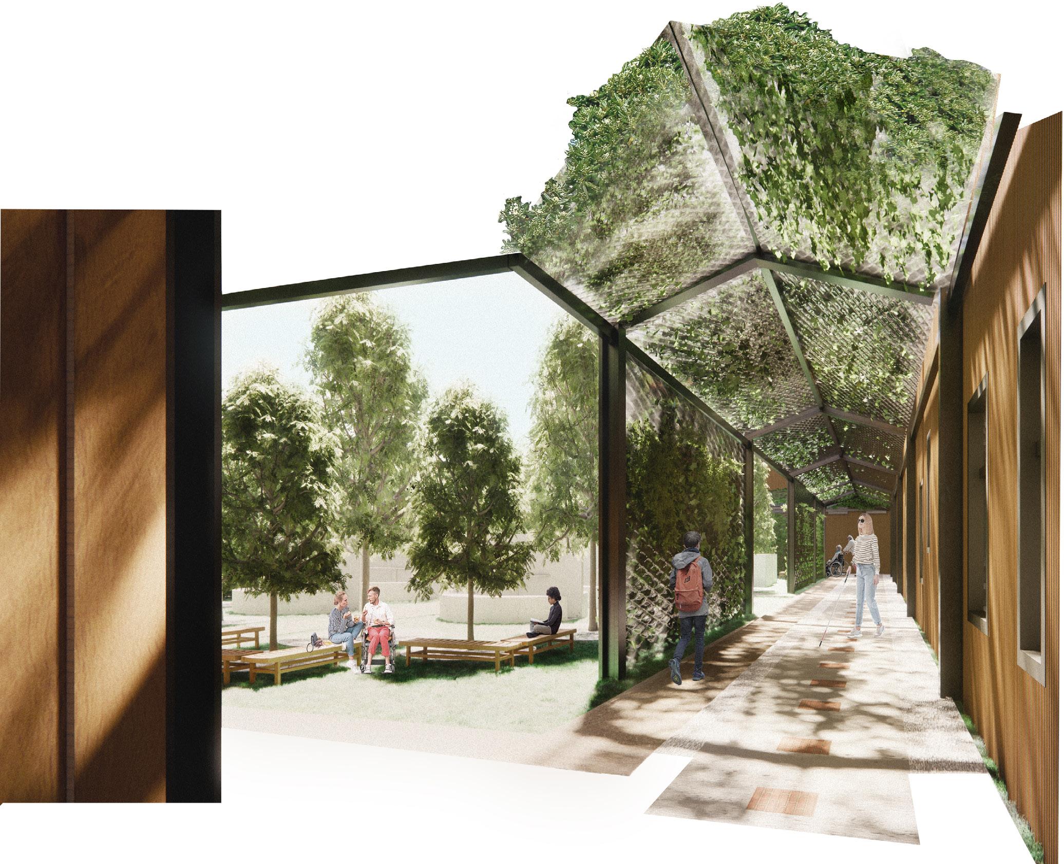
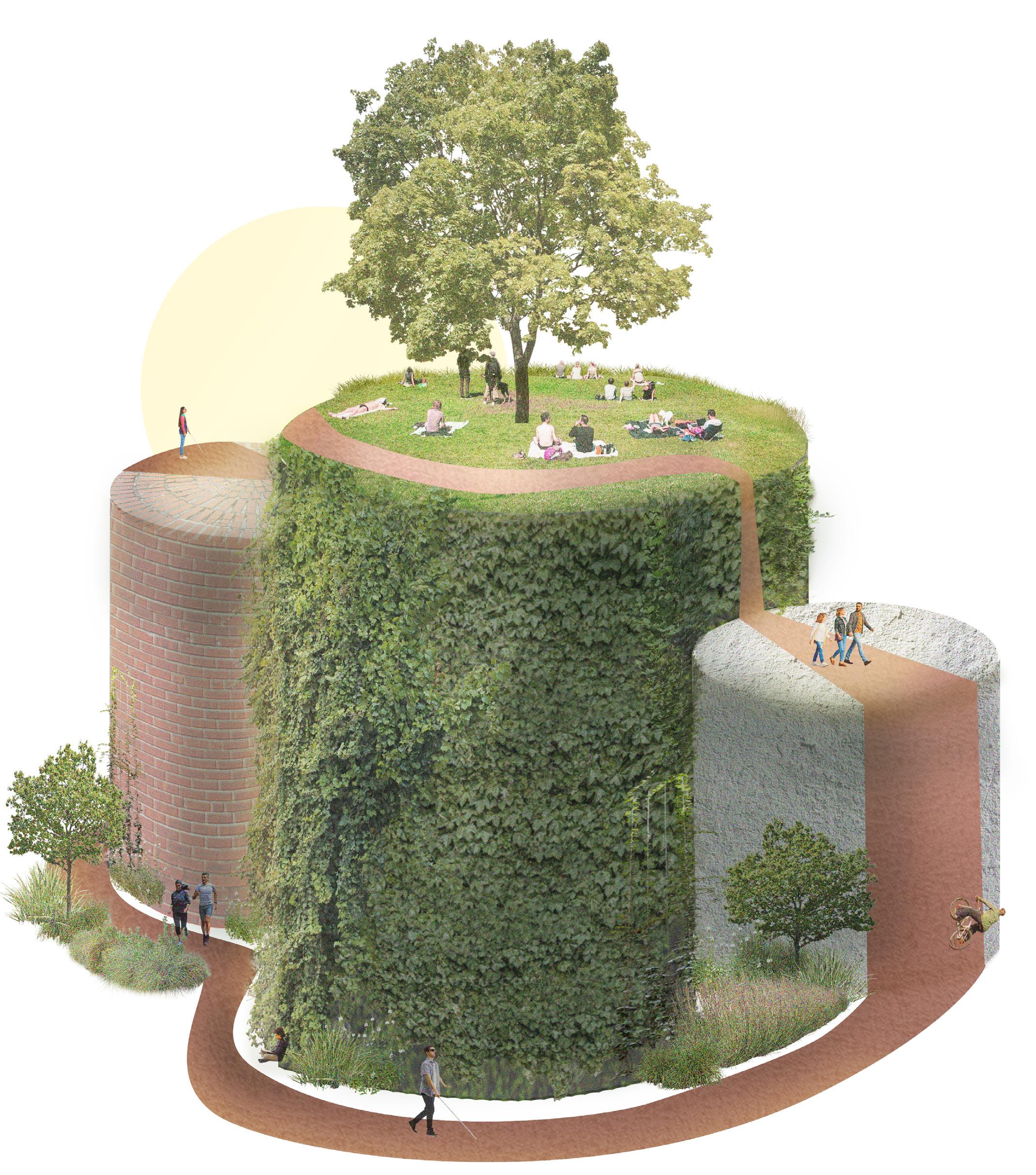
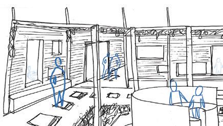
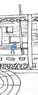
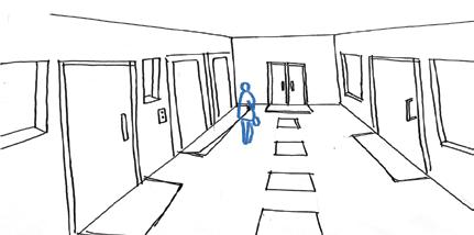
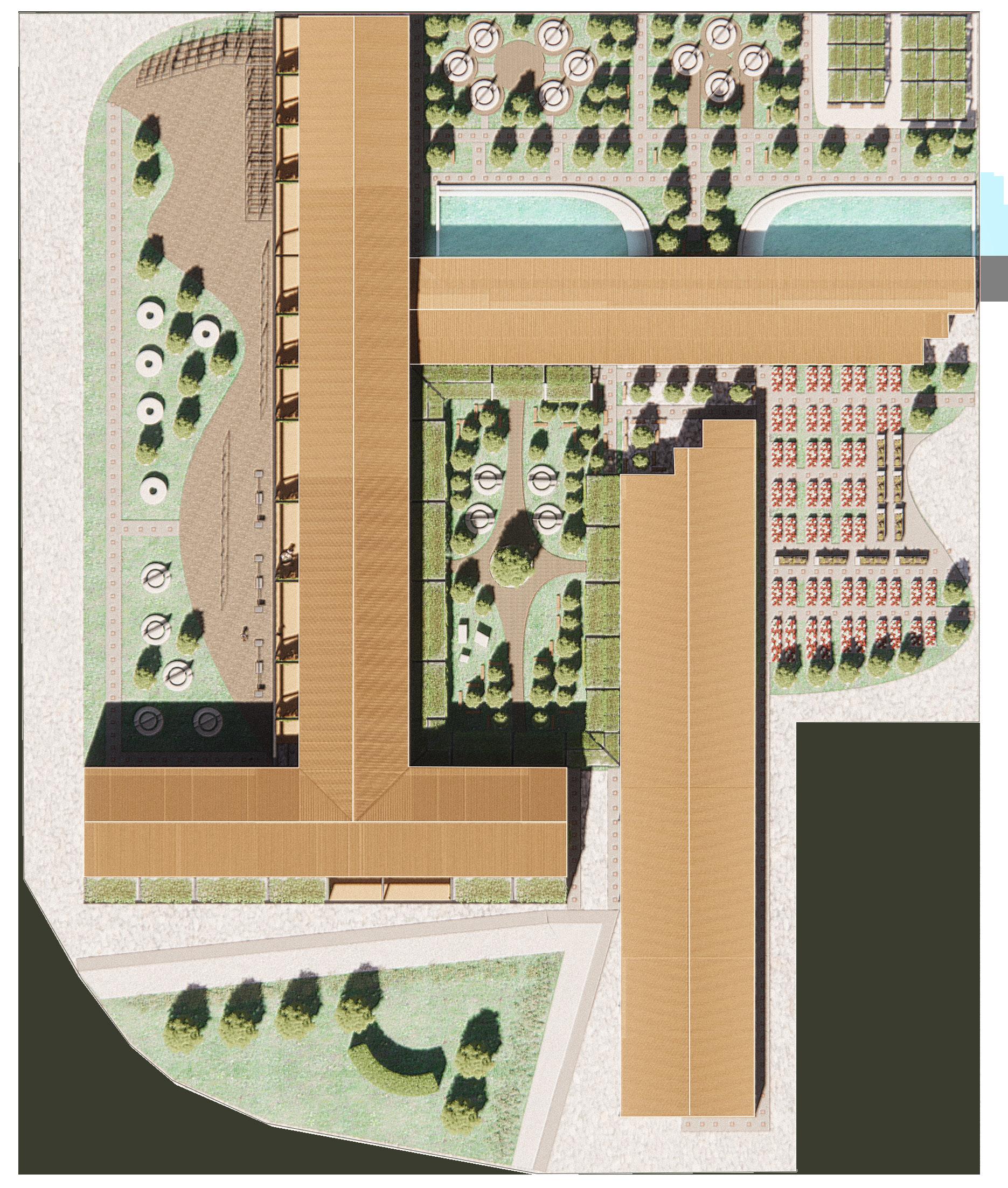
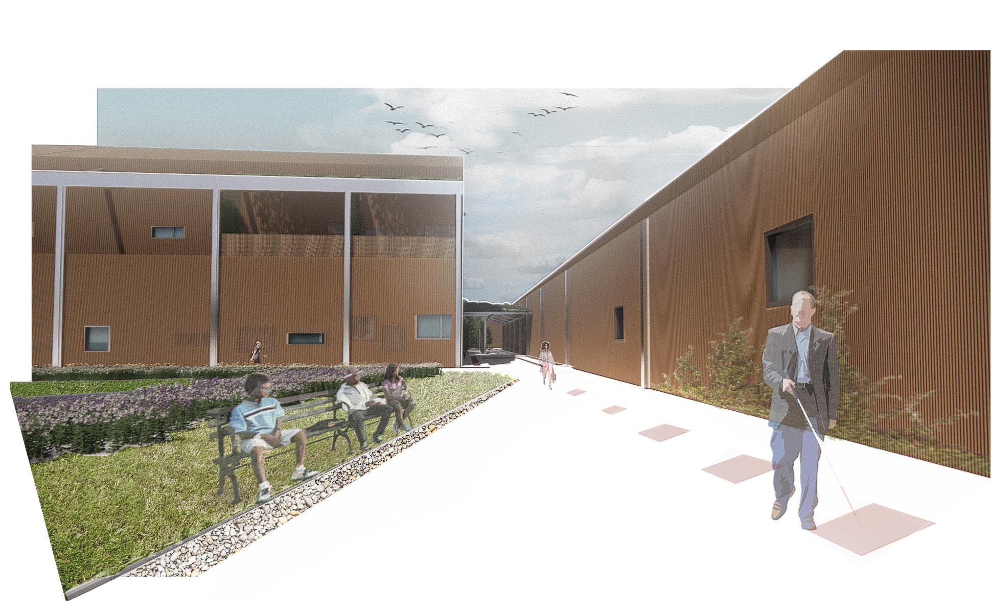
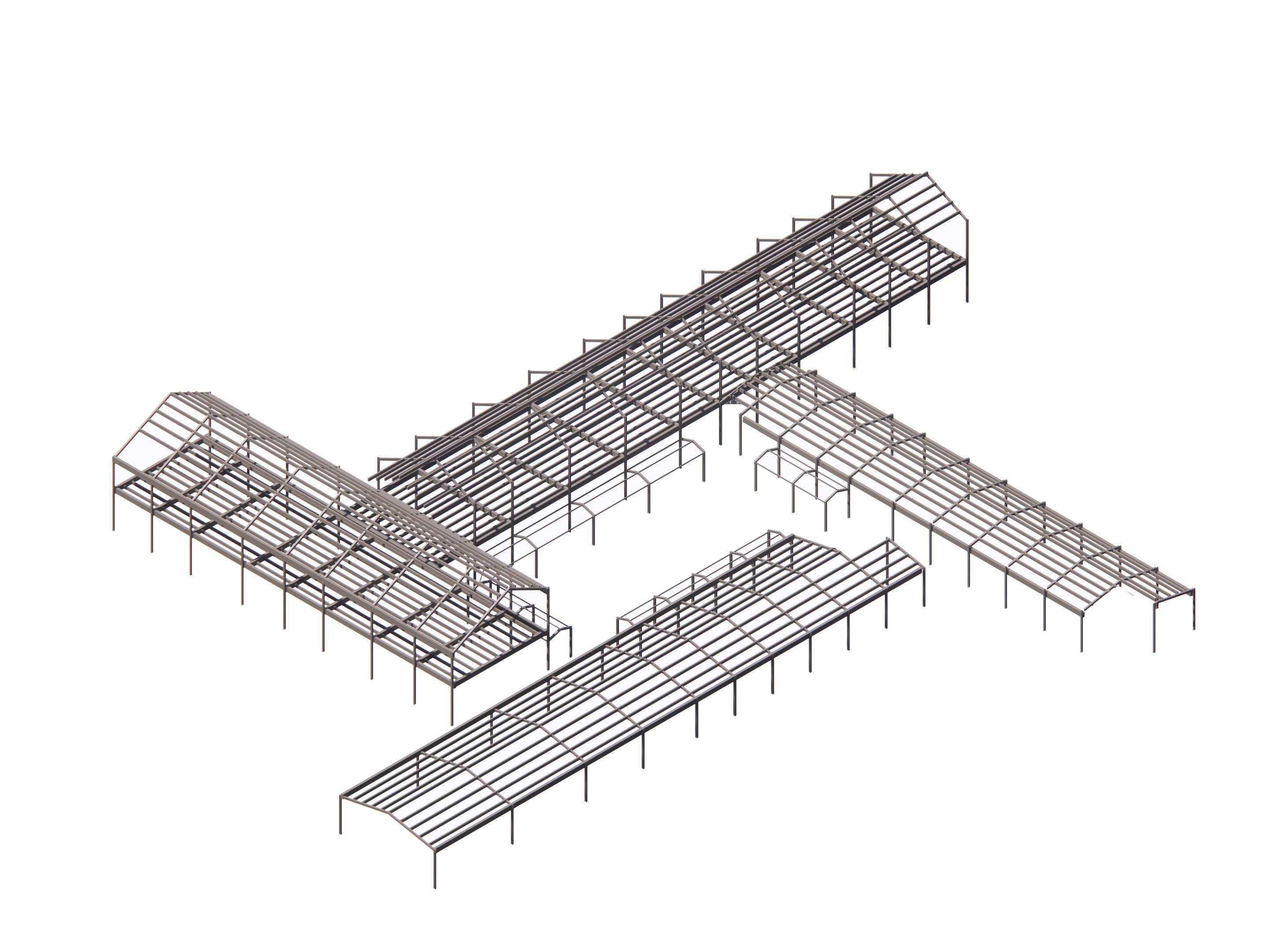
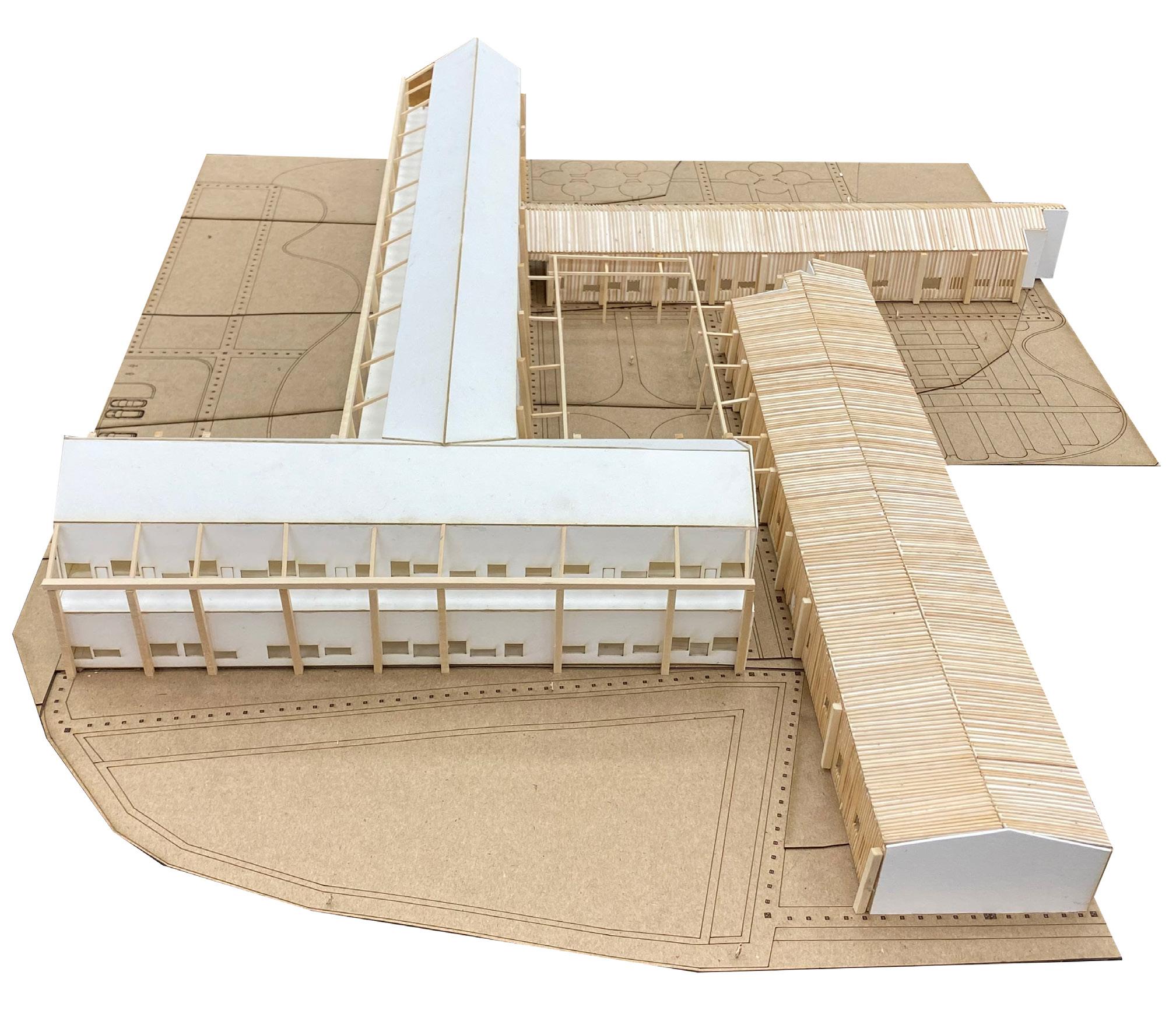
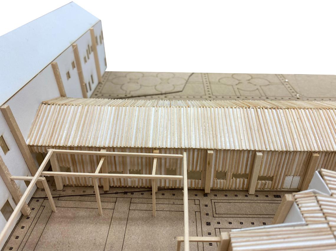
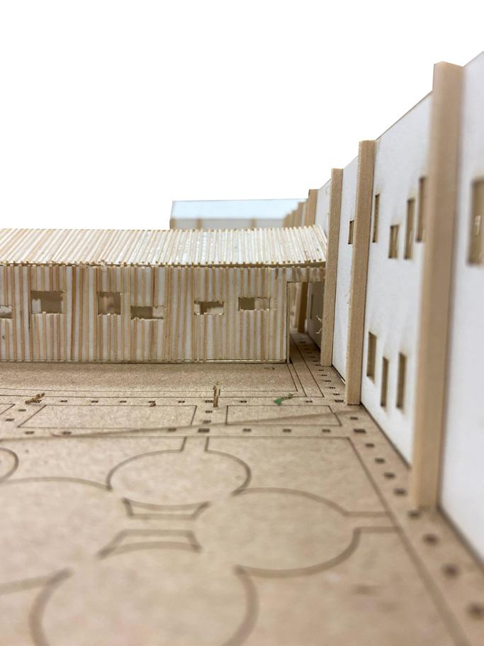
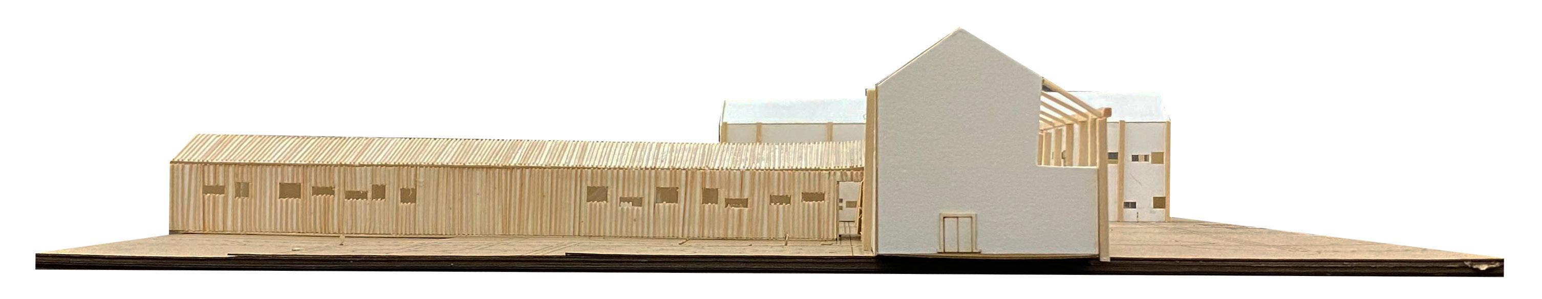
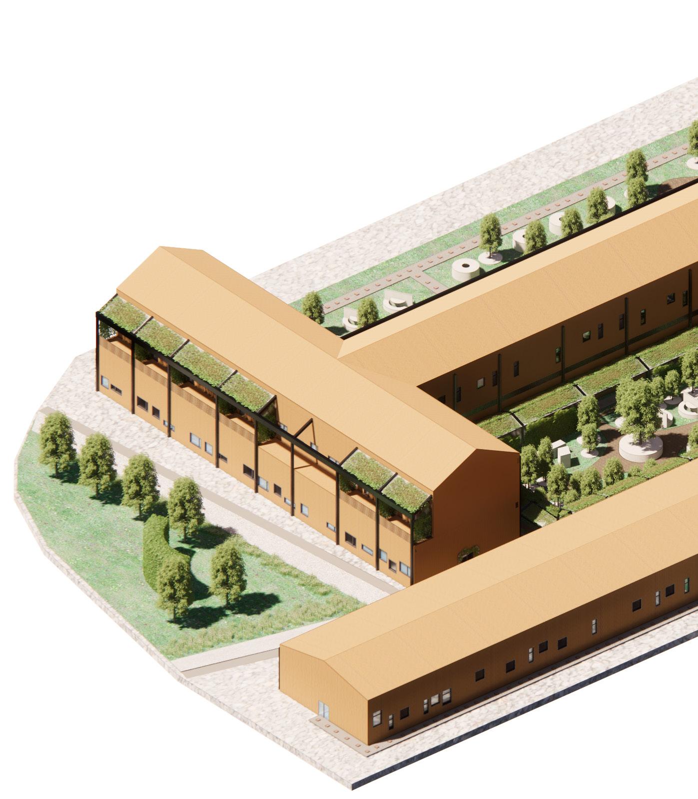
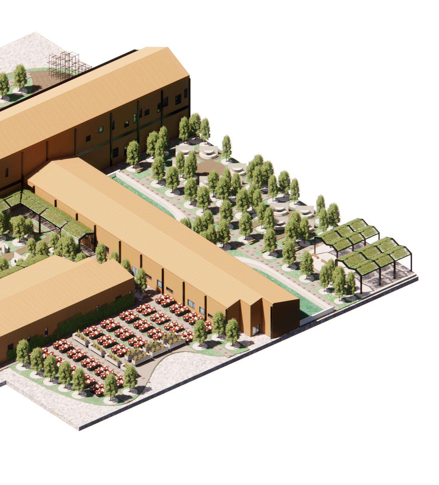
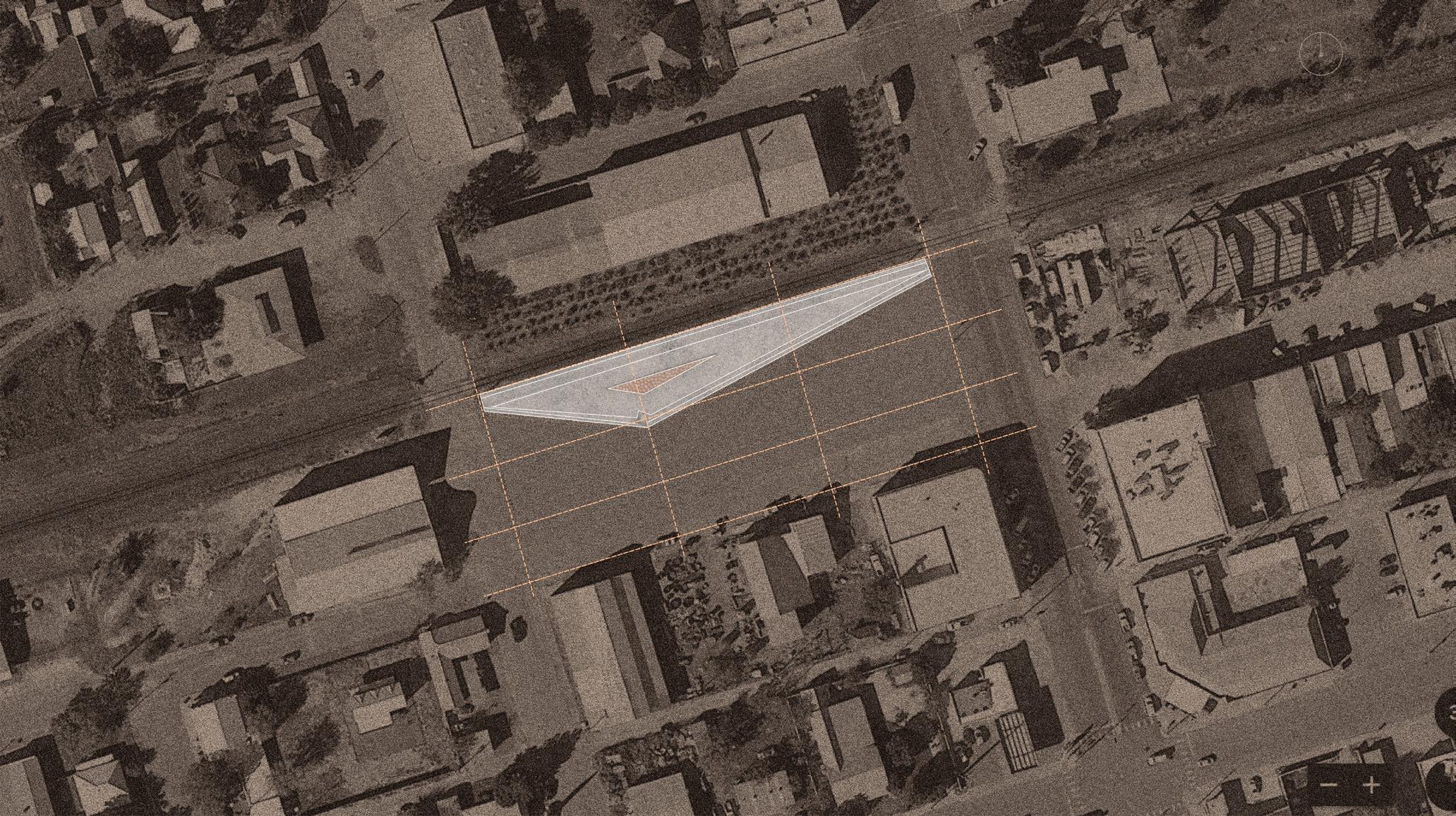
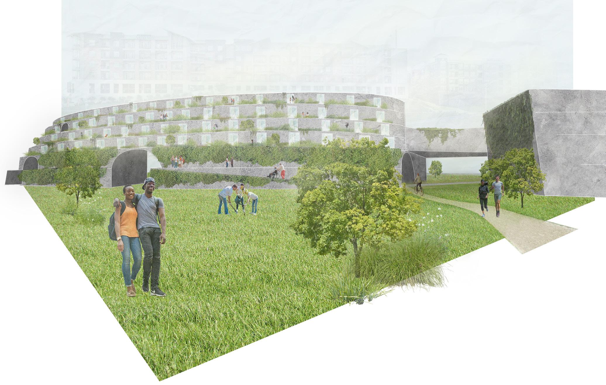
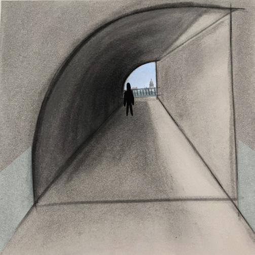
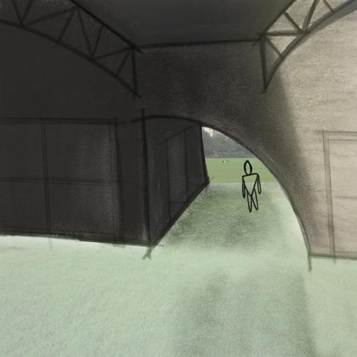
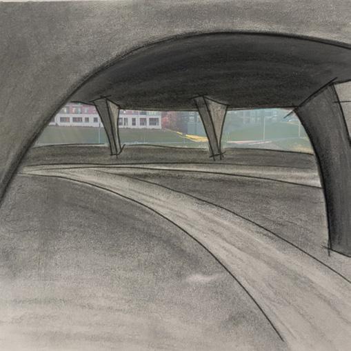
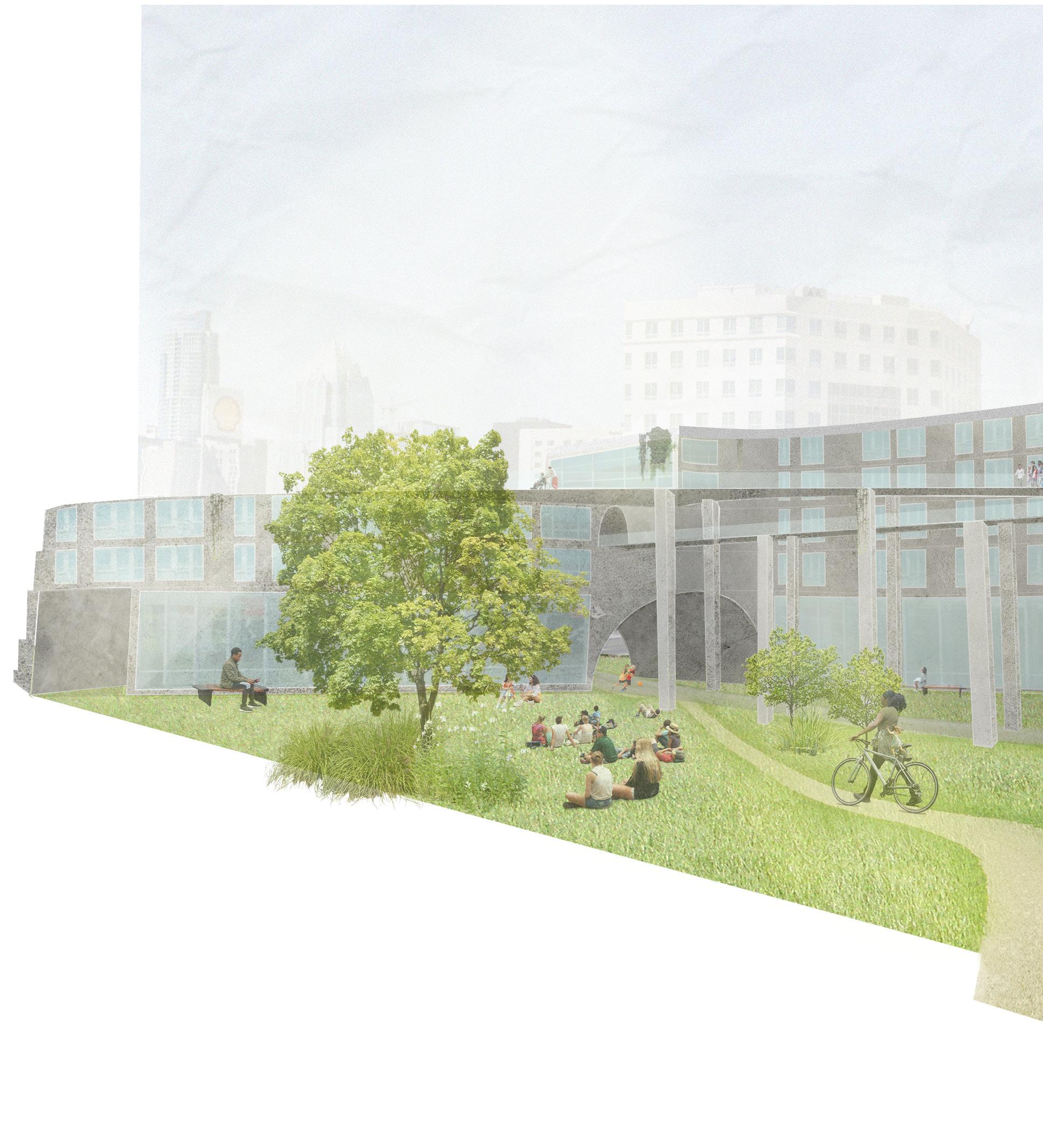
The Center aims to connect contrasting communities by establishing green spaces that serve as social gathering areas and provide a sensory experience for both the sighted and visually impaired through the exploration of the other four senses. Using a series of curated gardens designed to isolate and enhance one of the five senses, we aim to promote a more intuitive form of accessibility that fosters a connection between the community and the surrounding nature, while producing inclusive and accessible spaces. There is an element of rotational symmetry with the garden entrances that emphasize axiality and alignment in order to make circulation more intuitive. In order to organize the programmatic structure, the functions of each room are organized based on public, semi-private, and private spheres, with the public sphere being the most accessible to the outside and visitors and the private sphere existing primarily for students exclusively. The positioning of gardens and program works successfully through allowing the visually impaired to orient themselves through the various sensory experiences, while also providing types of learning spaces for students to utilize during the day. At night, the more public spaces are open to the community to take classes or participate in leisure activities.


VAPOR BARRIER
3/4” X 3/4” WOOD SCREEN CLADDING BATTENS AND COUNTER-BATTENS
PLYWOOD DECKING
RIGID INSULATION
WIDE FLANGE BEAM ATTACHED TO GIRDER
HIDDEN GUTTER SYSTEM
EXTERIOR STEEL BEAM/COLUMN
3/4” X 3/4” WOOD SCREEN CLADDING
BATTENS AND COUNTER BATTENS
RIGID INSULATION
STEEL JOIST
SUPPLY AND RETURN AIR WOOD SLAT ACOUSTIC CEILING
TILE FLOORING
UNCOUPLING MEMBRANE
CONCRETE SLAB ON GRADE
RIGID INSULATION

Primary Structure: Steel I-Columns (10” Width, 900 sq ft tributary area)
Secondary Structure: Steel I-Beams (14” Width, 28” Depth, 35-50’ span)
Tertiary Structure: Light Gauge Steel Joists, Steel Decking (Not Shown)
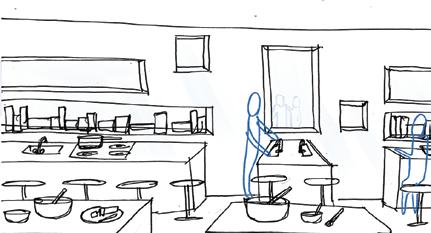
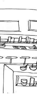
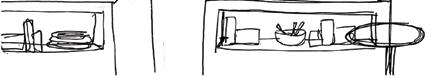
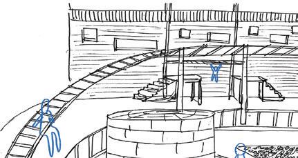
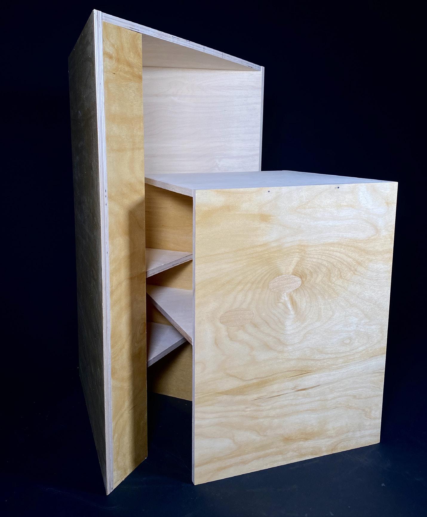
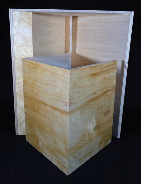
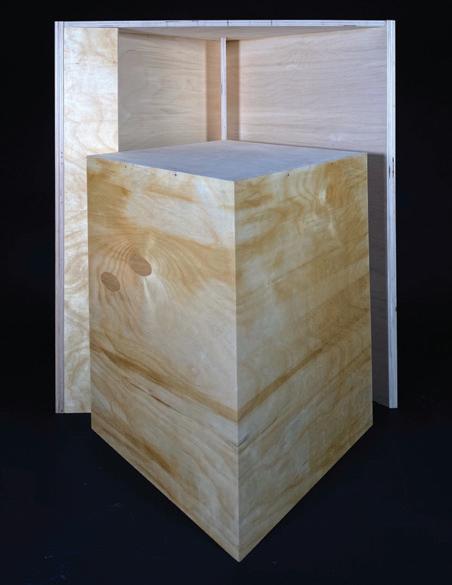
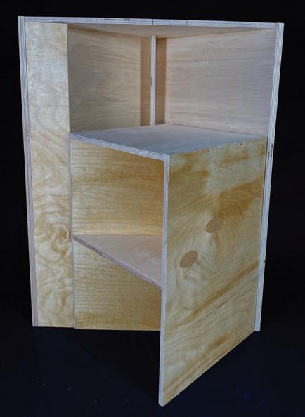
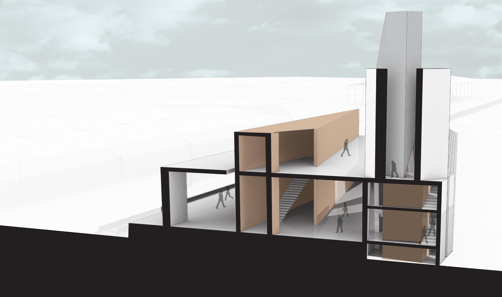
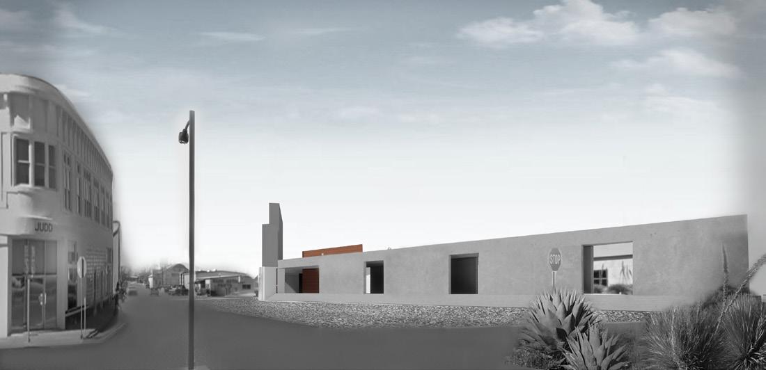
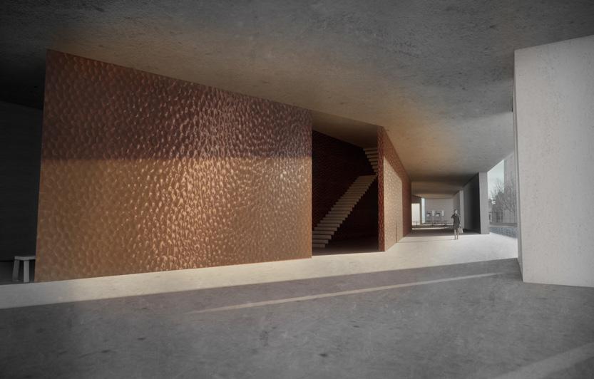
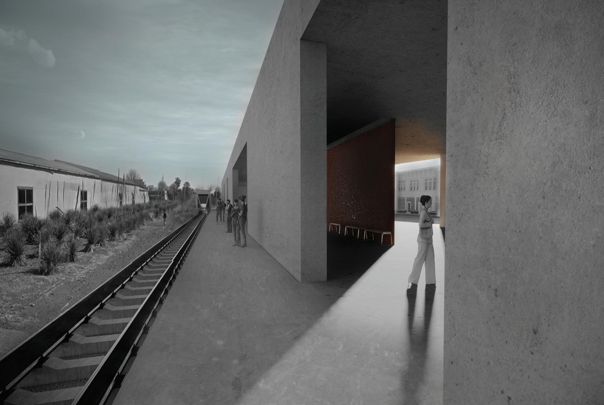
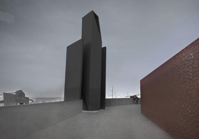
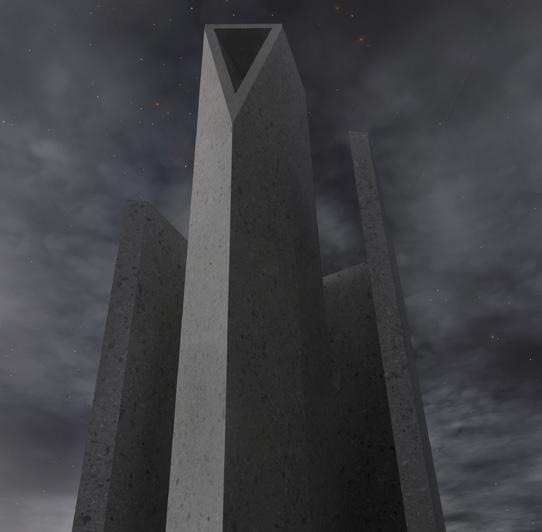
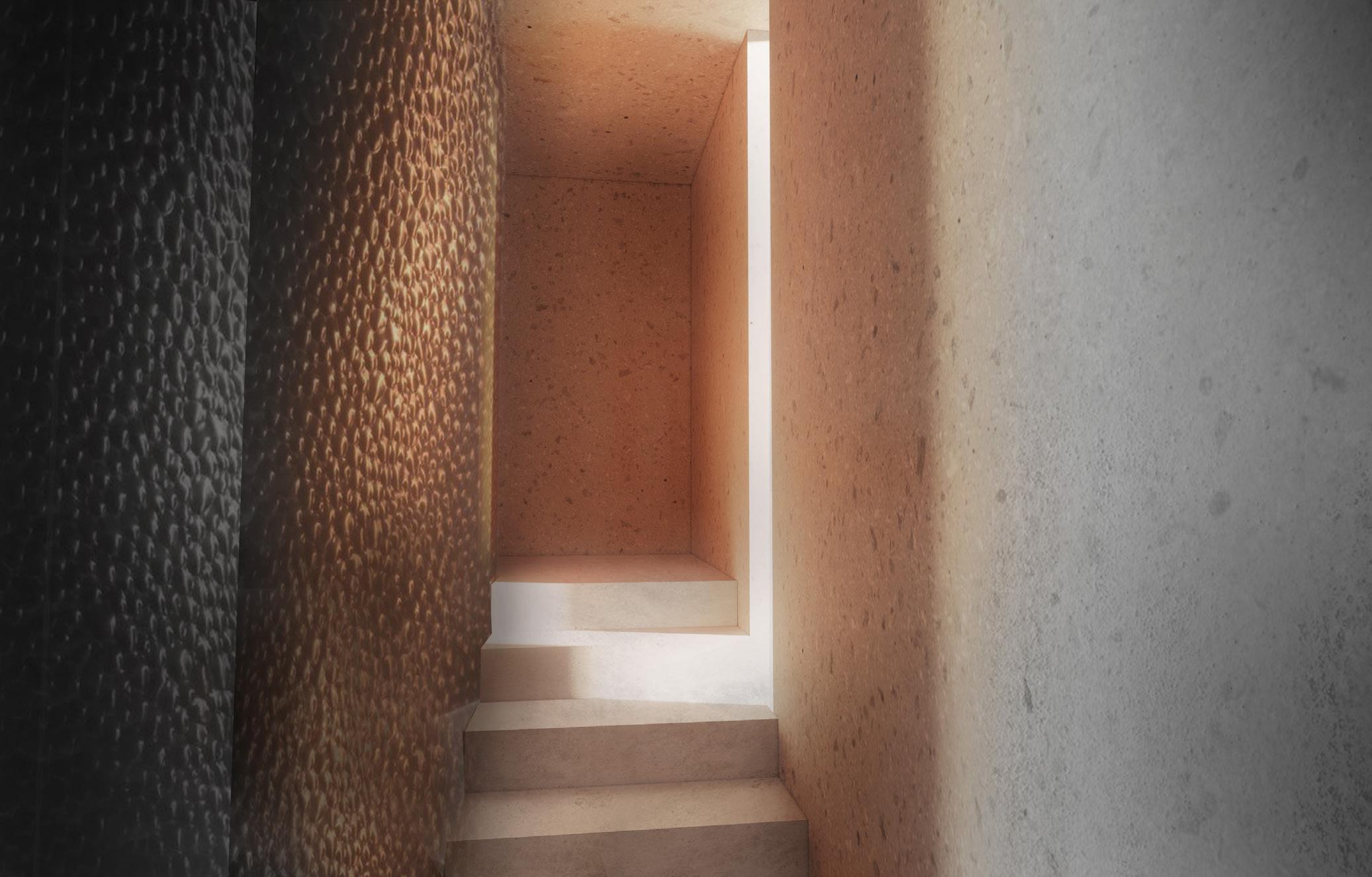
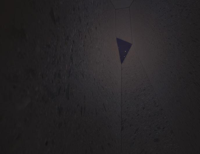
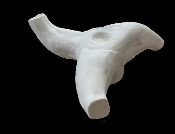
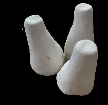
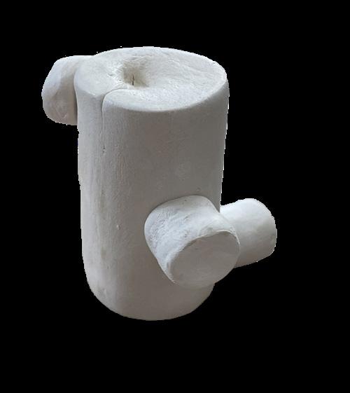
The Deep Time Station houses both an AMTRAK rail station and a deep time museum that helps to accentuate Marfa’s unique lighting qualities through varying light chambers. Before developing the Station, we were tasked with developing stools/seats that would reflect Judd’s ideas. They aimed to minimally produce a product that could be reoriented to reveal new interesting proportions and alignments. Within the final project and the Station itself- I aimed to take the ideas of Judd that we had focused on previously and incorporate them into the formal qualities of the structure. There is a focus on the primary ideas of circulation around a centerpiece, using different slots to create striated lighting qualities throughout the day, and creating systems of thirds to mimic Judd. The lower chamber is meant to be used during the day, and lets in very direct amounts of light. In contrast, the upper chamber can only be accessed by going to the roof and is meant for nighttime to give the user a direct view of the north star and to help them orient themselves within the universe. In addition, the entire second floor of the platform serves as a viewing platform for the user to observe Marfa’s natural beauty.
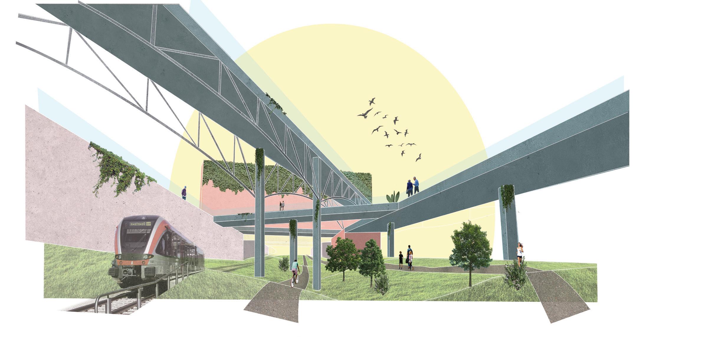
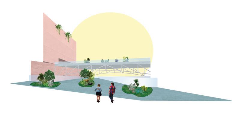
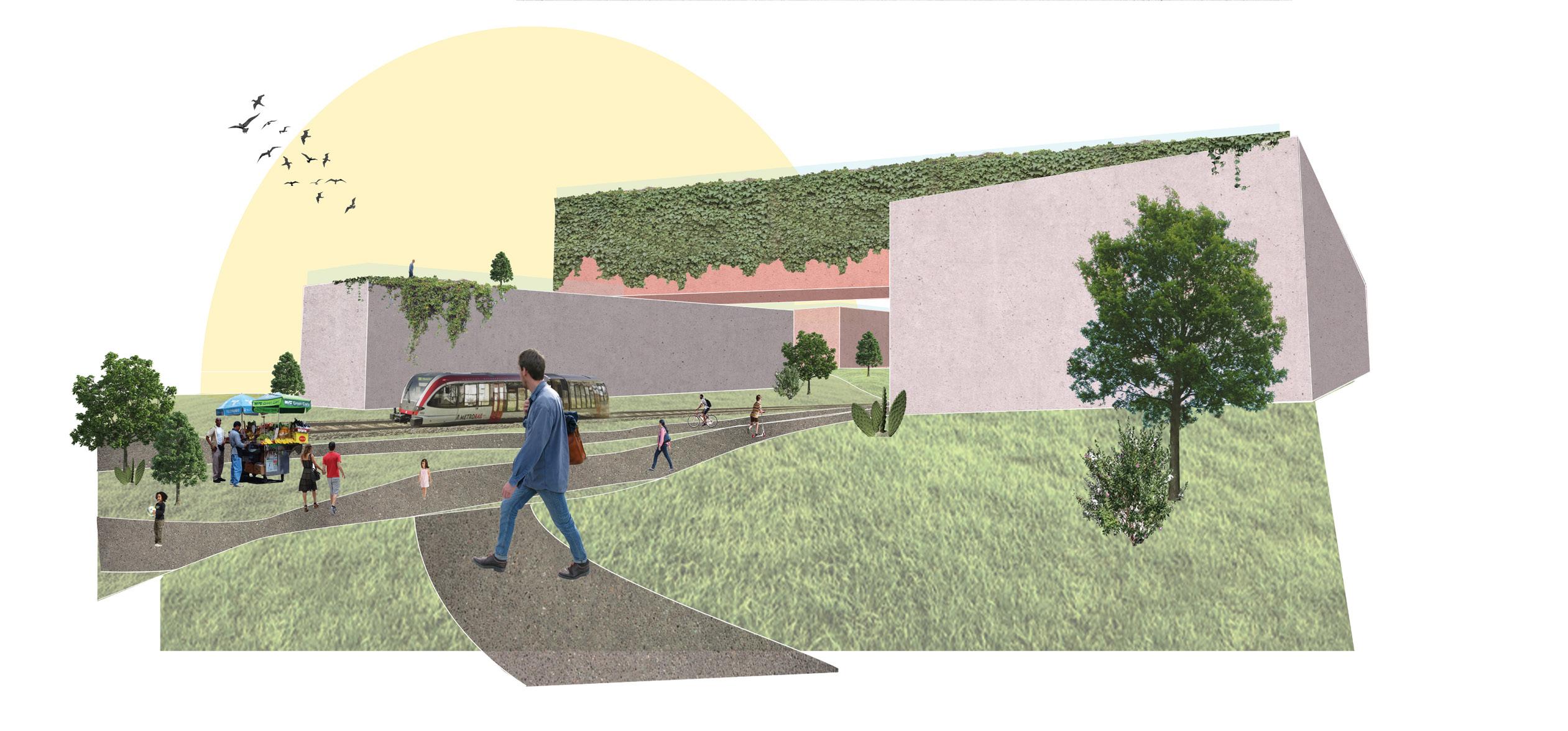
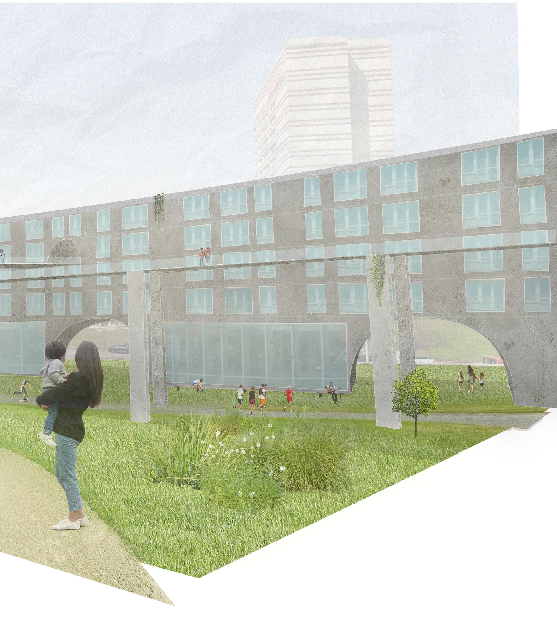
Bridging
Massing
LightRailPath Pedestrian+BikePath
AdjustedTopography
Transportation Pathways
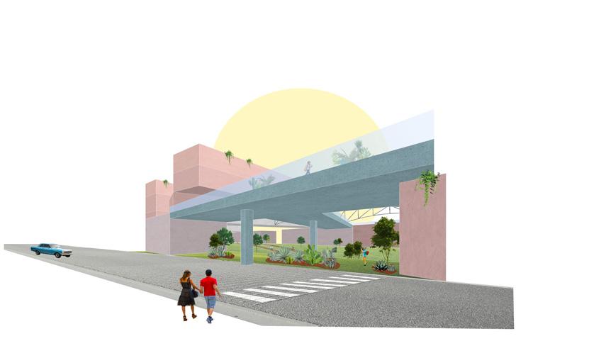

East/West Connections
Commerical Use
Massing (Commercial Use)
Residential use
Massing (Residential Use)
Primary Bridging
Primary Bridging
Secondary Bridging
Secondary Bridging
AdjustedTopography
Partners: Aya Wen, Isabelle Nance

SecondaryPublicEntry
MainPrivateEntry
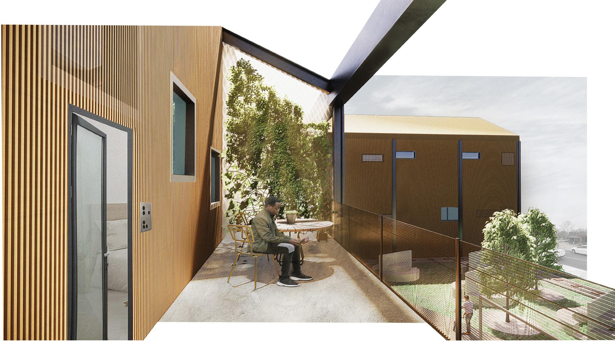
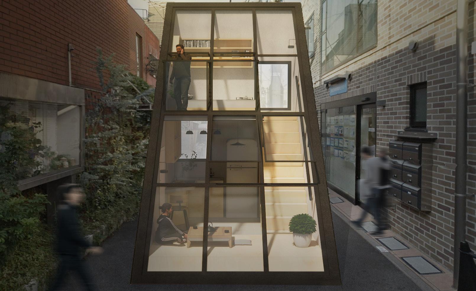
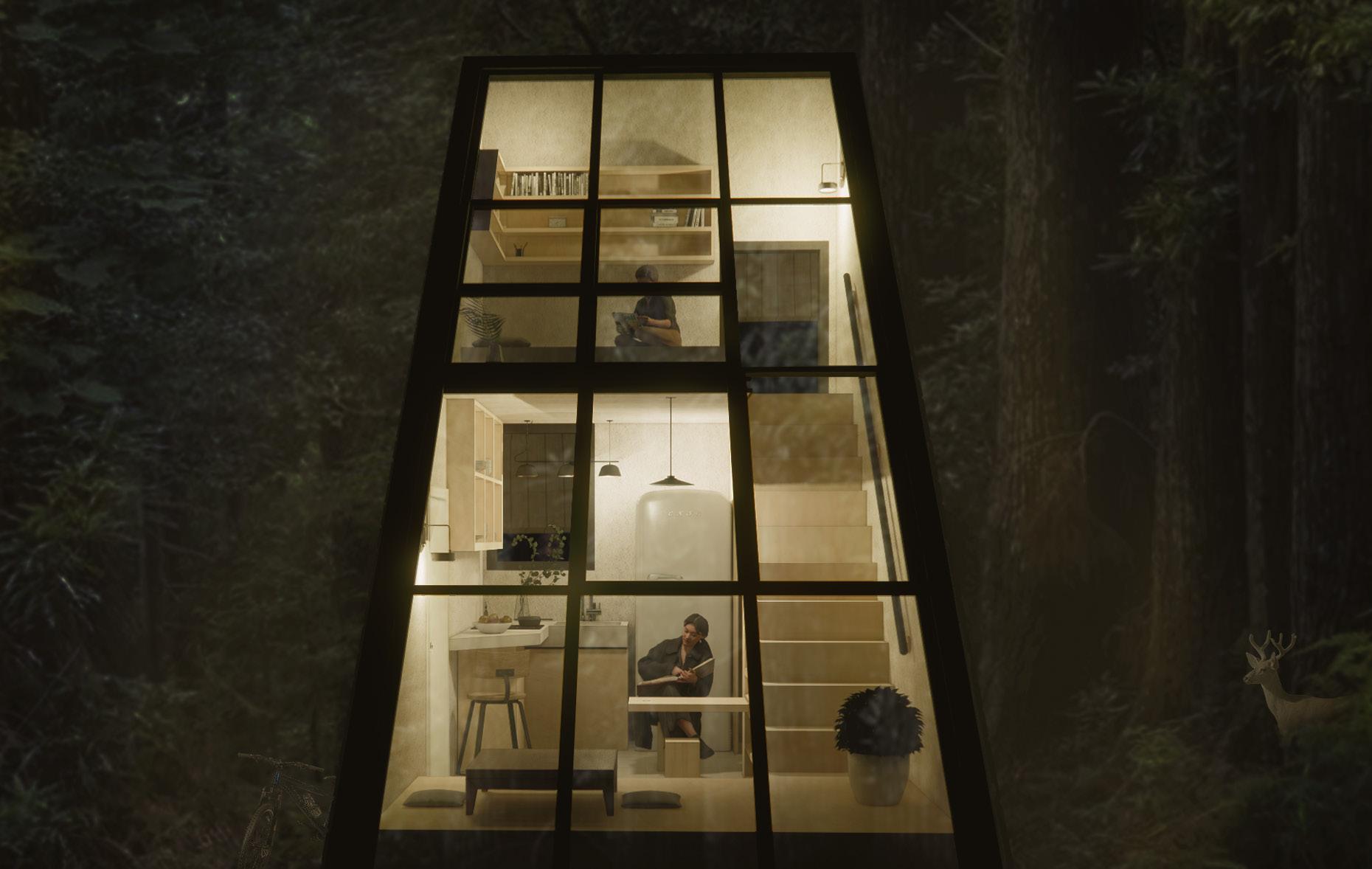
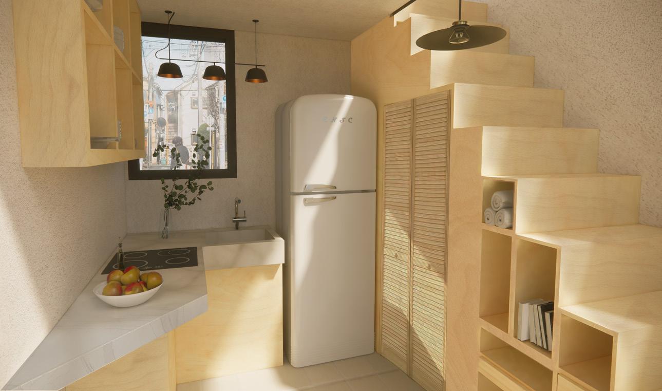
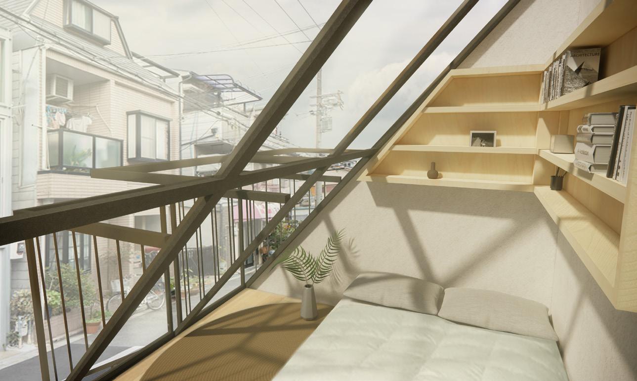
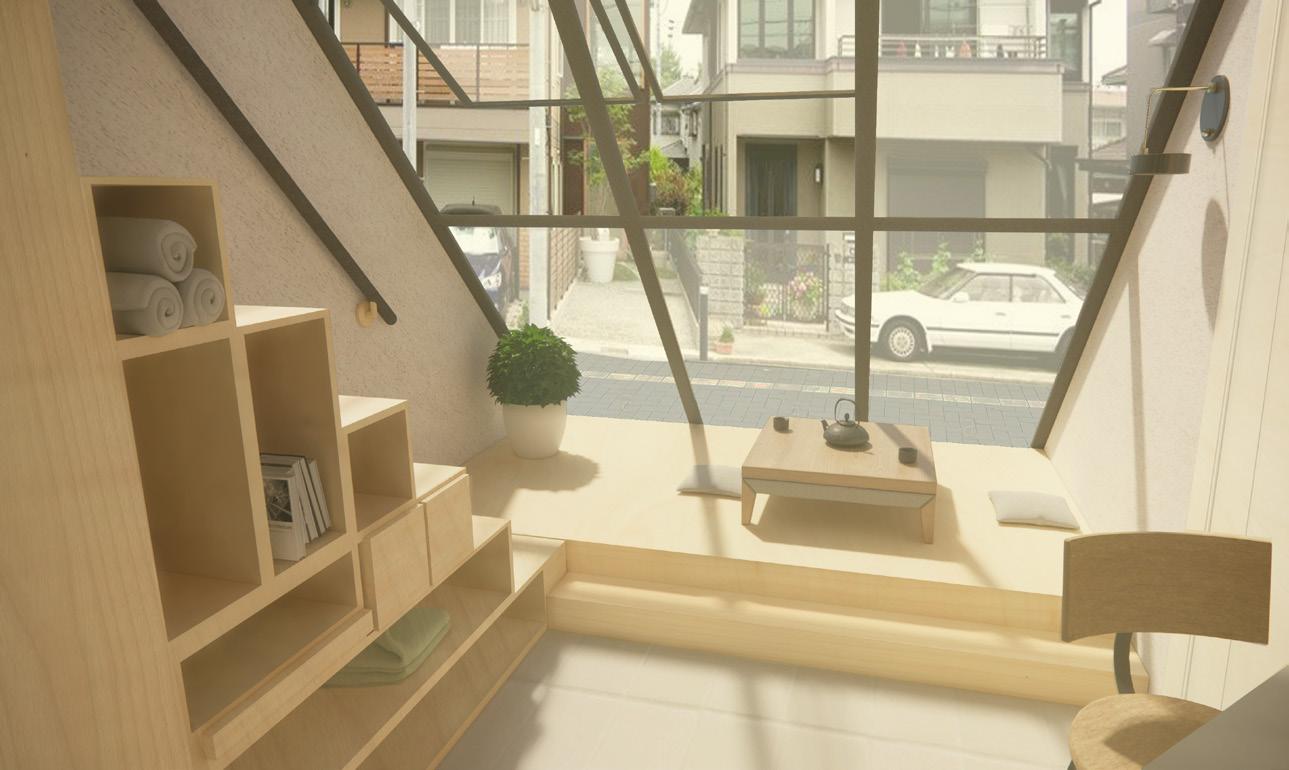
This competition was about not only creating a ‘tiny house’ but creating one that could be mobile if needed, and could function in different environments (with a focus on Japanese culture). Working in a team of 3 students, the design of the Ninety Degree House takes inspiration from modern Japanese geometries and building techniques. The structure has sharp formal qualities to contrast to any setting it’s in, forcing it to stand out within any environment. The slope ensures efficiency within varying weather conditions, allowing the mobile house to adapt to both urban and rural settings. A dialogue between the compact spaces and the expansive glass facade allows the us er to experience a spatial quality that feels greater than the true scale. With the addition of operable windows and balconies on this facade, the design is able to grow and better connect with its outside context. We also wanted to explore the idea of a potential solution for overcrowding within cities, and did so through making a structure narrow and lightweight enough to fit into small pathways or even an alleyway in Tokyo, Japan.
Fall 2020
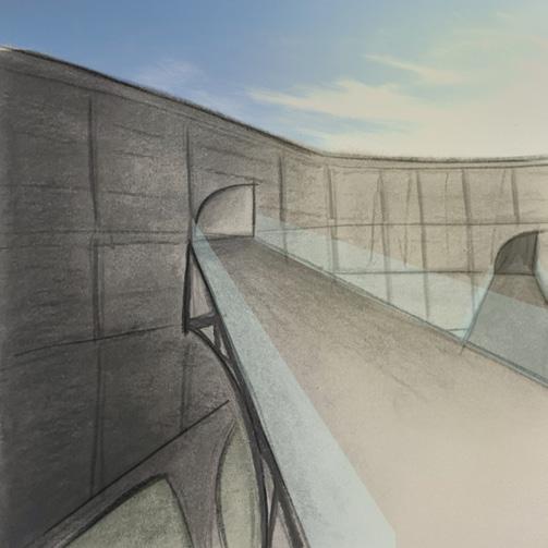
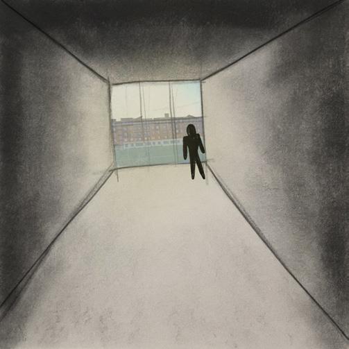
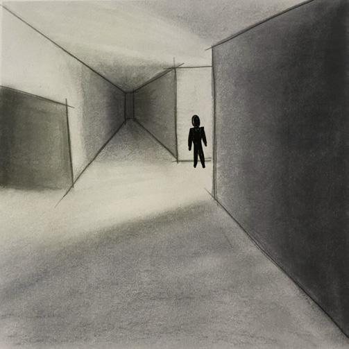
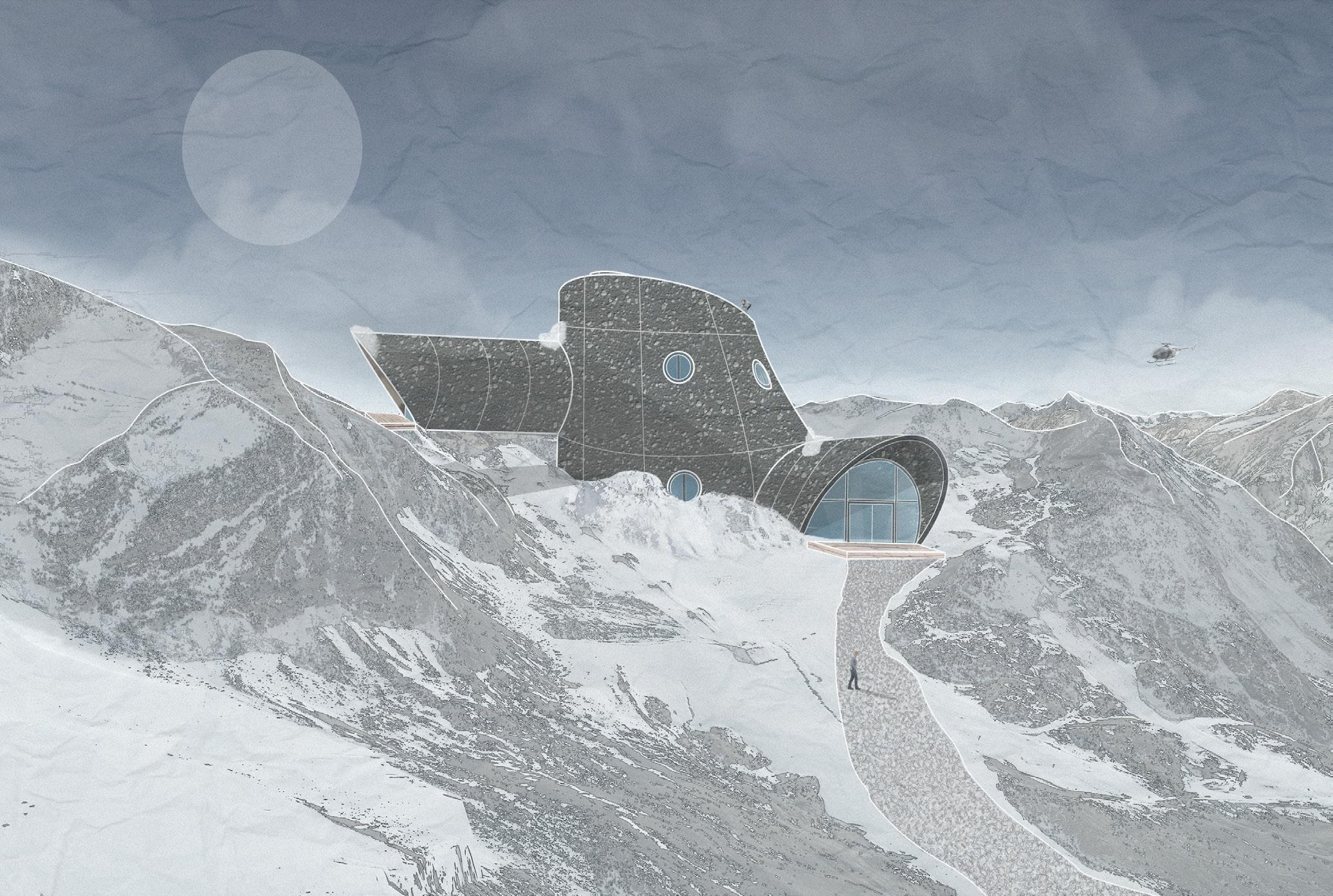
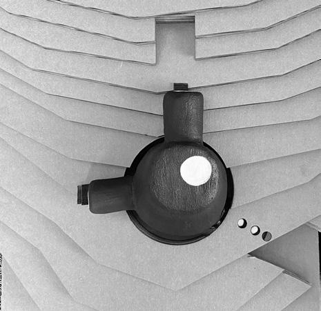
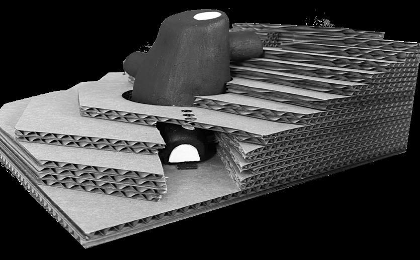
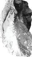
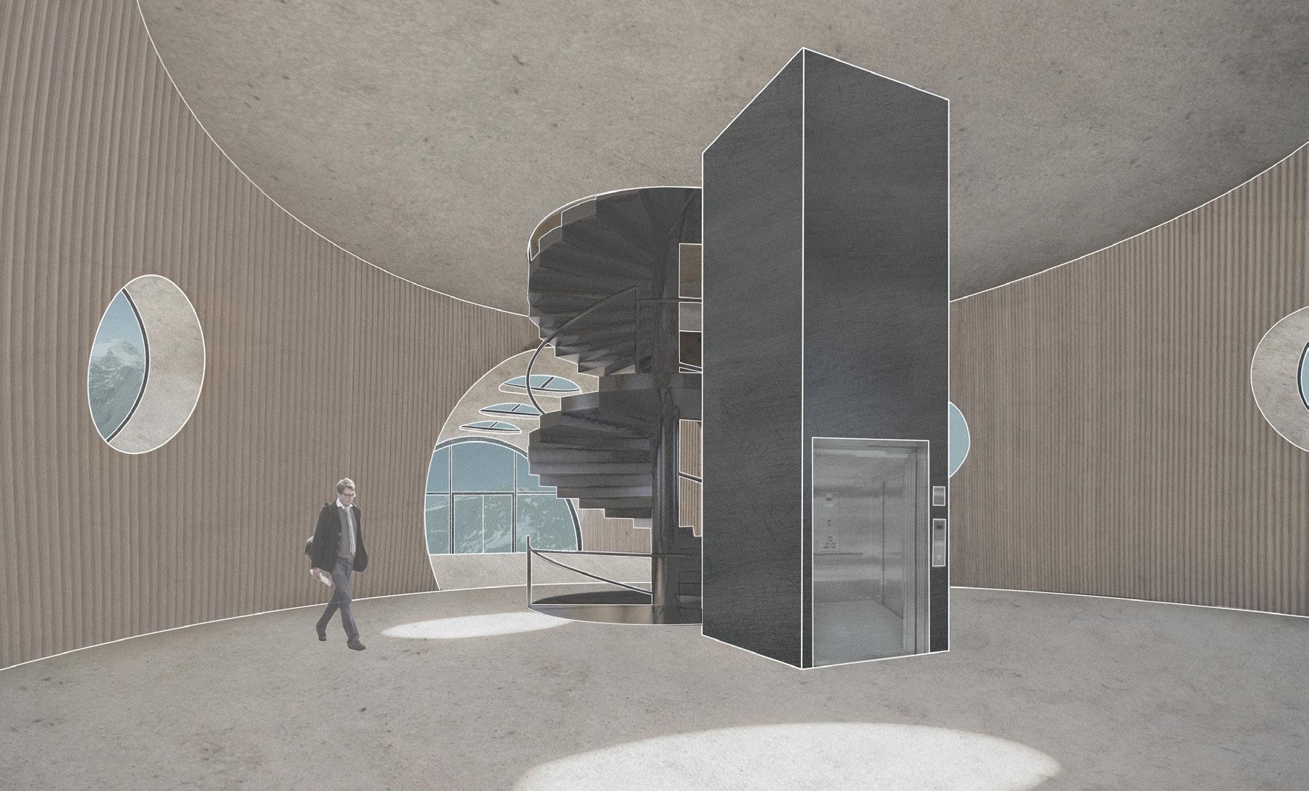
The Otzi Facility exists to not only survive in a harsh environment, but also to be a place for humans to study extreme earthly conditions such as climate change. The project aims to mimic the conceptual idea of branching, as well as reimagine the idea of how bunker-like structures function within extreme environments. With these concepts as a base, the project relates to the contextual site through not only being embedded within it, but also through creating very specific forced viewpoints and blending into the landscape through materiality and tapering of the form. The project is a resistant structure, meant to create a safe and warm interior for users to escape the harsh outside environment. The Facility branches both physically and conceptually, as it allows humans to not only separate from past ideologies and grow in knowledge, but physically consider what it means to live while embedded within the landscape.
Italian Alps
Fall 2020


Lateral
Materiality
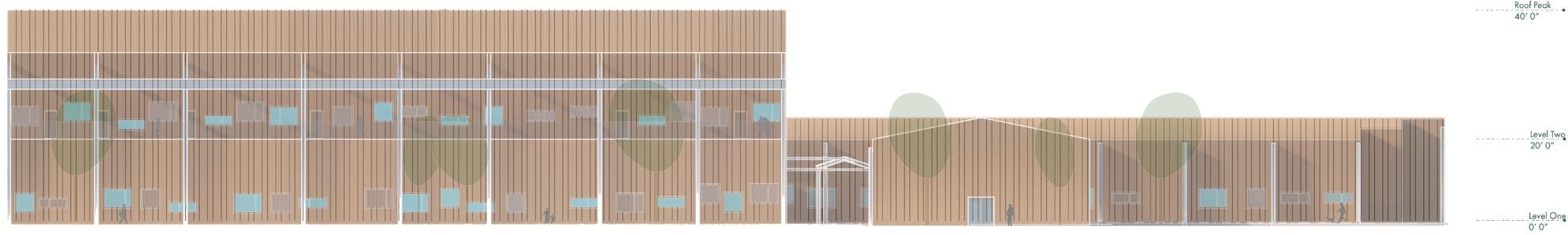
From the exterior my building is meant to look like a large concrete shell, with no visibility of the structure underneath. All of the structural systems will be hidden, expect for the shear wall system that you will be able to see from the interior. All of the connections between steel elements are pin joints with bolted connections, allowing for rotation but not translation.
Lateral Structure
From the exterior my building is meant to look like a large concrete shell, with no visibility of the structure underneath. All of the structural systems will be hidden, expect for the shear wall system that you will be able to see from the interior. All of the connections between steel elements are pin joints with bolted connections, allowing for rotation but not translation.
Lateral
From the exterior my building is meant to look like a large concrete shell, with no visibility of the structure underneath. All of the structural systems will be hidden, expect for the shear wall system that you will be able to see from the interior. All of the connections between steel elements are pin joints with bolted connections, allowing for rotation but not translation.
Vertical Structure
Connection
Connection between steel frame vertical + horizontal + diagonal elements (using bolted connections)
A_Steel Braced Framing (Primary Structure)
A_Steel Braced Framing (Primary Structure)
Modeled similarly to how Frank Gehry acomplishes organic forms, (more specifically Guggenheim Bilbao) I decided to go with a steel frame grid. This grid is comprised of horizontal and vertical members with all members being straight and connecting at nodal points, and the horizontal members being at a constant elevation. These nodal points would be connected through bolted connections, meaning that the pin joints will allow rotation but resist translation. The grid spacing is approximately 5’x5’ as this allows the framing to conform with the curves of the form and maintain structural stability. The vertical members are 4” deep wide flange structural steel members, with the horizontal members being steel I-beams that are 3” in depth.
Modeled similarly to how Frank Gehry acomplishes organic forms, (more specifically Guggenheim Bilbao) I decided to go with a steel frame grid. This grid is comprised of horizontal and vertical members with all members being straight and connecting at nodal points, and the horizontal members being at a constant elevation. These nodal points would be connected through bolted connections, meaning that the pin joints will allow rotation but resist translation. The grid spacing is approximately 5’x5’ as this allows the framing to conform with the curves of the form and maintain structural stability. The vertical members are 4” deep wide flange structural steel members, with the horizontal members being steel I-beams that are 3” in depth.
Modeled similarly to how Frank Gehry acomplishes organic forms, (more specifically Guggenheim Bilbao) I decided to go with a steel frame grid. This grid is comprised of horizontal and vertical members with all members being straight and connecting at nodal points, and the horizontal members being at a constant elevation. These nodal points would be connected through bolted connections, meaning that the pin joints will allow rotation but resist translation. The grid spacing is approximately 5’x5’ as this allows the framing to conform with the curves of the form and maintain structural stability. The vertical members are 4” deep wide flange structural steel members, with the horizontal members being steel I-beams that are 3” in depth.
B_Shear Core Walls (Secondary Structure)
B_Shear Core Walls (Secondary Structure)
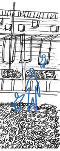
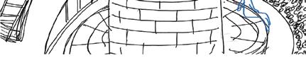
To provide additional lateral support, there are shear core walls within the structure that are continuous between multiple floors. These walls are highlighted in blue in the exploded axon. The shear core is 20’ in width, 20’ in length, and 30’ in height (it is located within both the first and second floors)
To provide additional lateral support, there are shear core walls within the structure that are continuous between multiple floors. These walls are highlighted in blue in the exploded axon. The shear core is 20’ in width, 20’ in length, and 30’ in height (it is located within both the first and second floors)
To provide additional lateral support, there are shear core walls within the structure that are continuous between multiple floors. These walls are highlighted in blue in the exploded axon. The shear core is 20’ in width, 20’ in length, and 30’ in height (it is located within both the first and second floors)
C_Wide
C_Wide
To combat the vertical load, the floor assembly includes a system of steel I-beams, girders and decking.
To combat the vertical load, the floor assembly includes a system of steel I-beams, girders and decking.
To combat the vertical load, the floor assembly includes a system of steel I-beams, girders and decking.
The I-beams span 14” between the girders, and have a depth of 6“ with a height of 0.7’ (which I determined based on the 1:20 rule of thumb, and have rounded up to 0.75‘ or 9”).
The I-beams span 14” between the girders, and have a depth of 6“ with a height of 0.7’ (which I determined based on the 1:20 rule of thumb, and have rounded up to 0.75‘ or 9”).
The I-beams span 14” between the girders, and have a depth of 6“ with a height of 0.7’ (which I determined based on the 1:20 rule of thumb, and have rounded up to 0.75‘ or 9”).
There are also wide flange steel girders, spaning perpendicularly to the beams. They are sized as follows:
There are also wide flange steel girders, spaning perpendicularly to the beams. They are sized as follows:
There are also wide flange steel girders, spaning perpendicularly to the beams. They are sized as follows:
First Floor: No girders
First Floor: No girders
First Floor: No girders
Second Floor: Girders span between 40’ and 71’, with their depth being 36”, and their height is 3.55‘ (which I determined based on the 1:20 rule of thumb)
Second Floor: Girders span between 40’ and 71’, with their depth being 36”, and their height is 3.55‘ (which I determined based on the 1:20 rule of thumb)
Second Floor: Girders span between 40’ and 71’, with their depth being 36”, and their height is 3.55‘ (which I determined based on the 1:20 rule of thumb)
Third Floor: Girders span between 30’ and 56’, with their depth being 34”, and their height is 2.80‘ (which I determined based on the 1:20 rule of thumb)
Third Floor: Girders span between 30’ and 56’, with their depth being 34”, and their height is 2.80‘ (which I determined based on the 1:20 rule of thumb)
Third Floor: Girders span between 30’ and 56’, with their depth being 34”, and their height is 2.80‘ (which I determined based on the 1:20 rule of thumb)
Roof: Girders span between 28’ and 44’, with their depth being 28”, with their height being 2.2’ (which I determined based on the 1:20 rule of thumb)
Roof: Girders span between 28’ and 44’, with their depth being 28”, with their height being 2.2’ (which I determined based on the 1:20 rule of thumb)
Roof: Girders span between 28’ and 44’, with their depth being 28”, with their height being 2.2’ (which I determined based on the 1:20 rule of thumb)
The steel floor decking is sized the same on every floor, spanning 14’ and is 6” in depth. The roof steel decking is different though, and spans 14’ with a depth of 3”.
The steel floor decking is sized the same on every floor, spanning 14’ and is 6” in depth. The roof steel decking is different though, and spans 14’ with a depth of 3”.
Steel frame vertical element and its connectionto ground (using bolted connections) 06 _ Otzi Anthropocene Research Facility
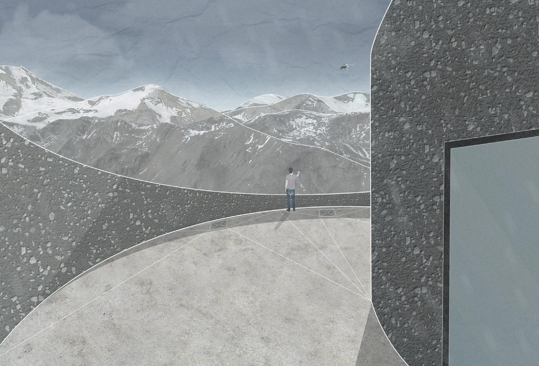
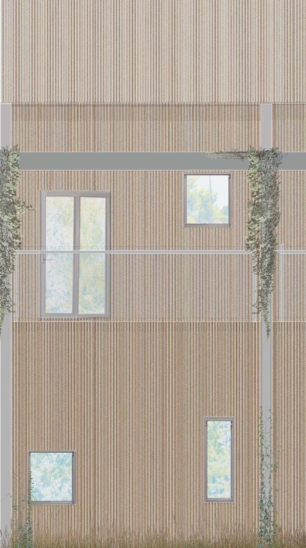
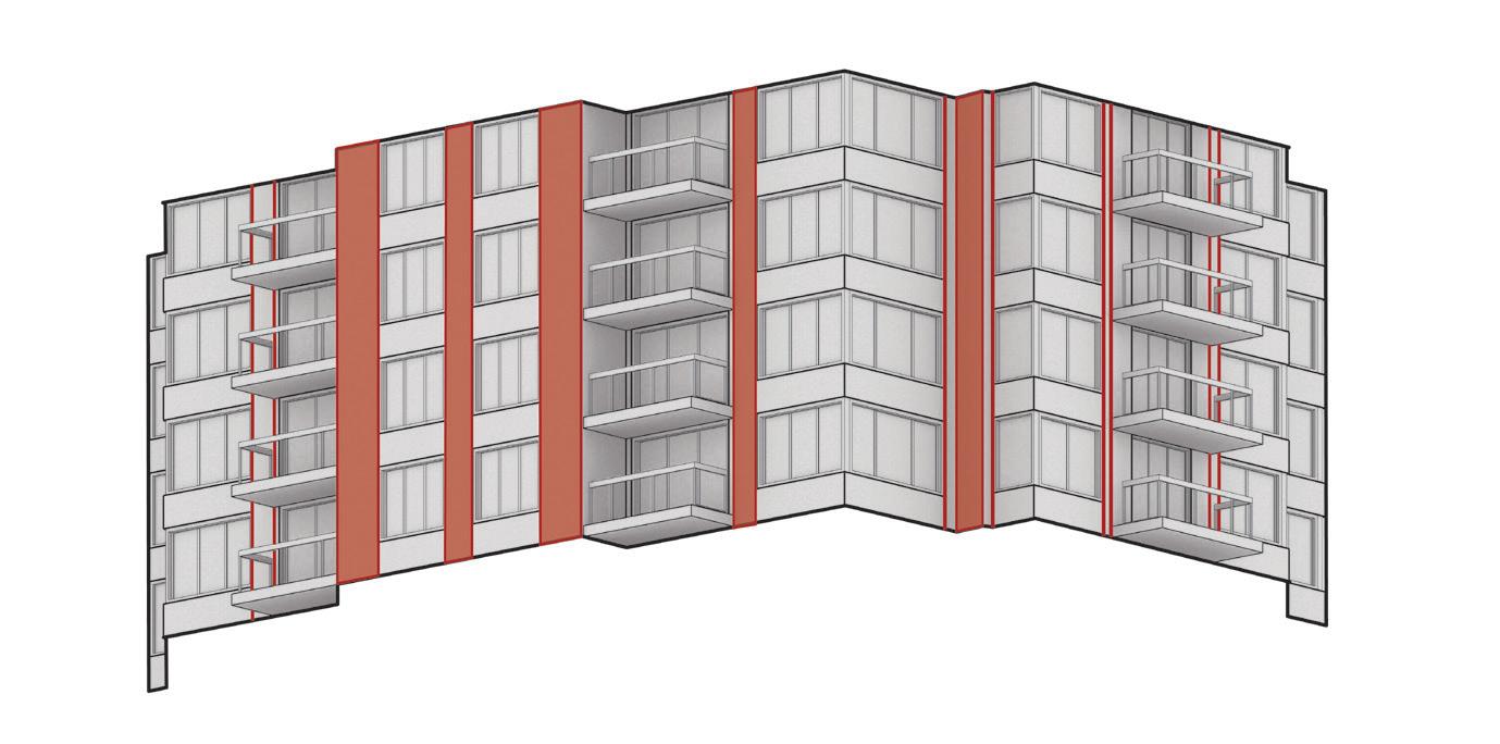
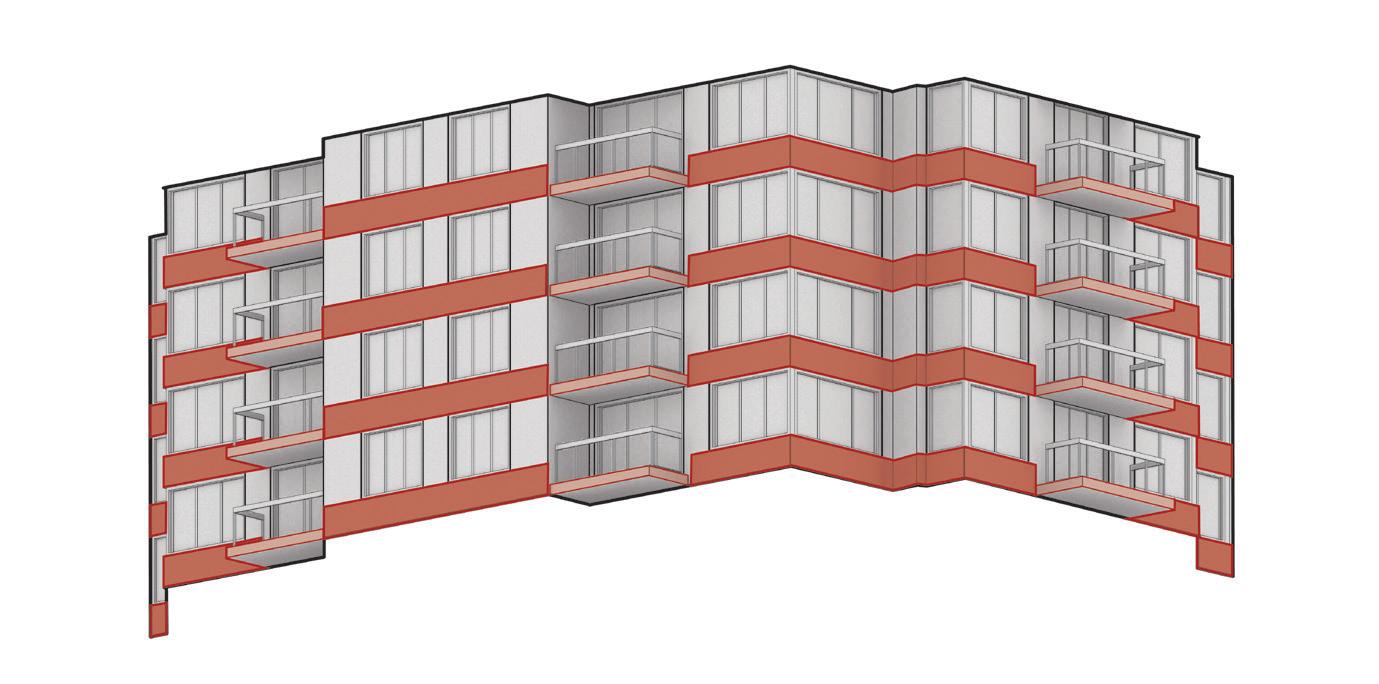
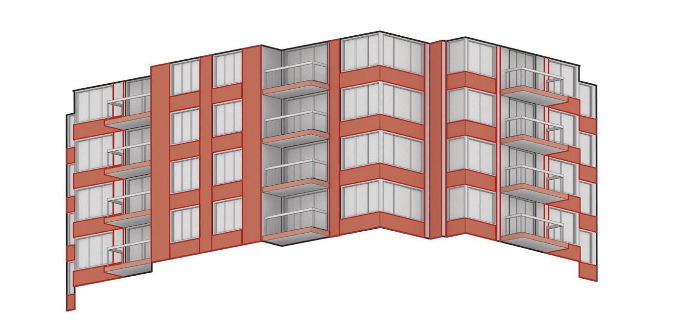
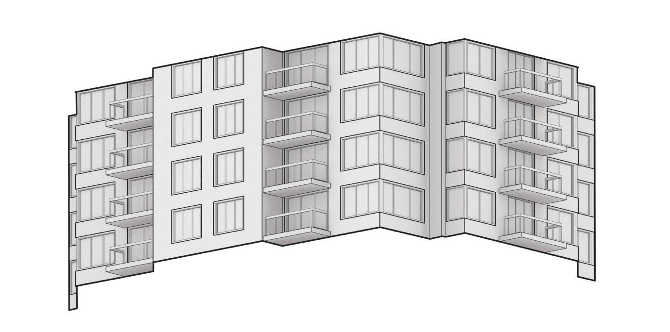
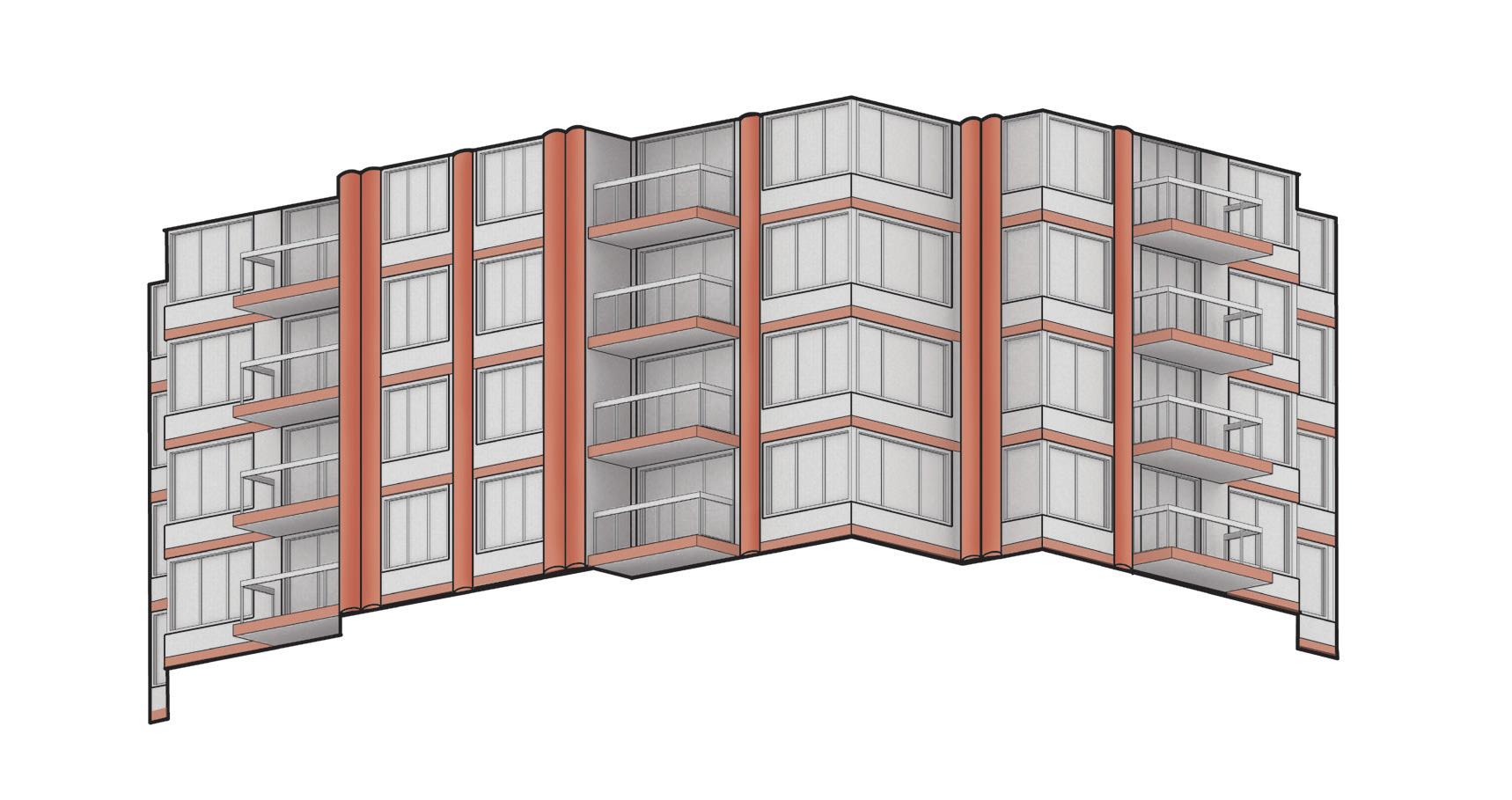
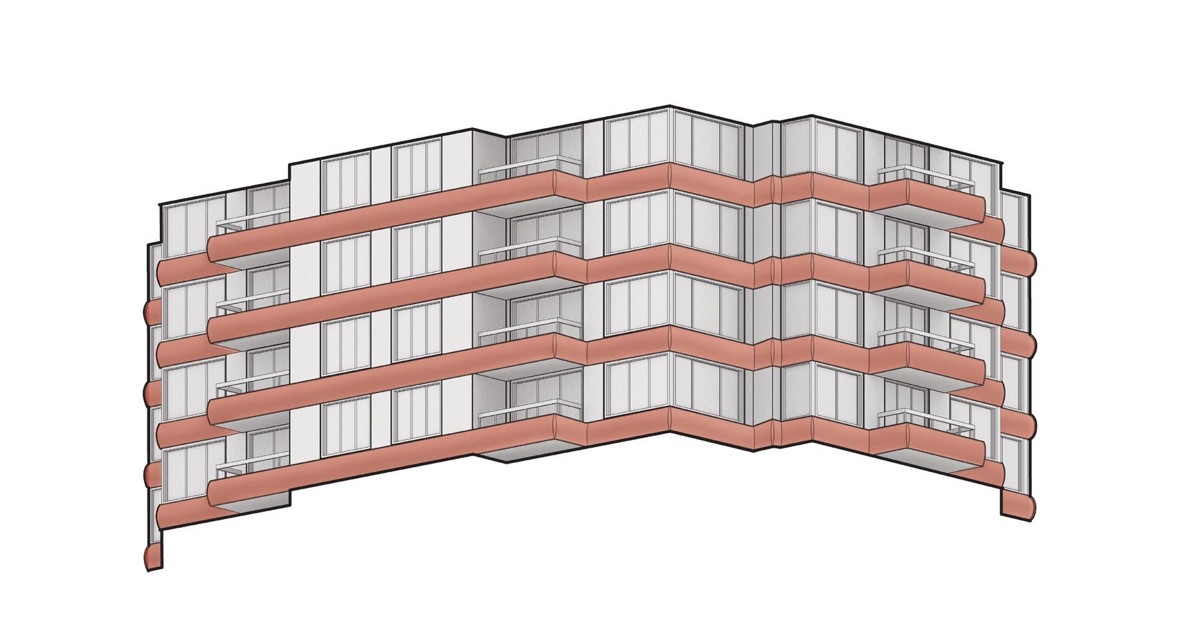
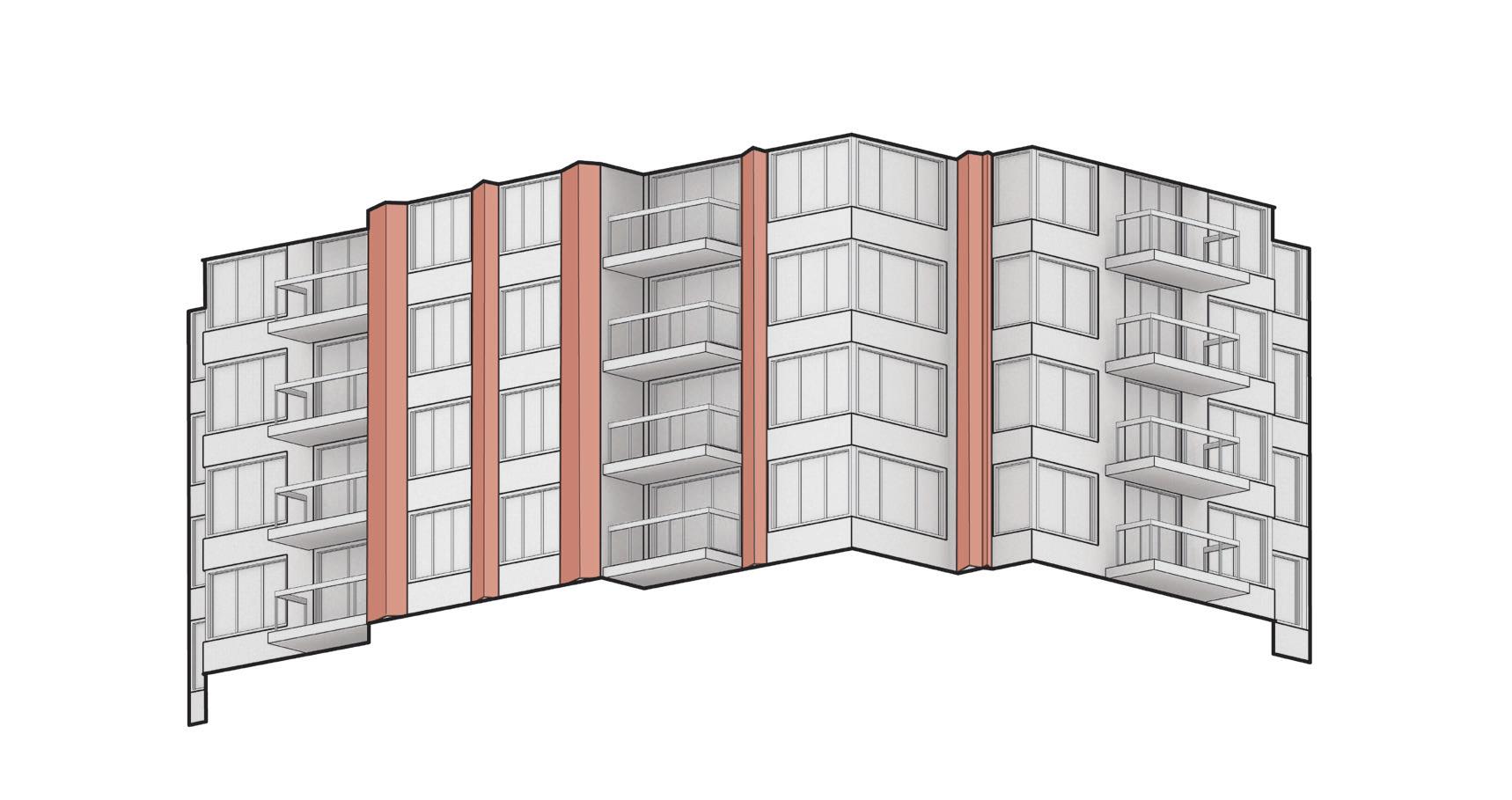
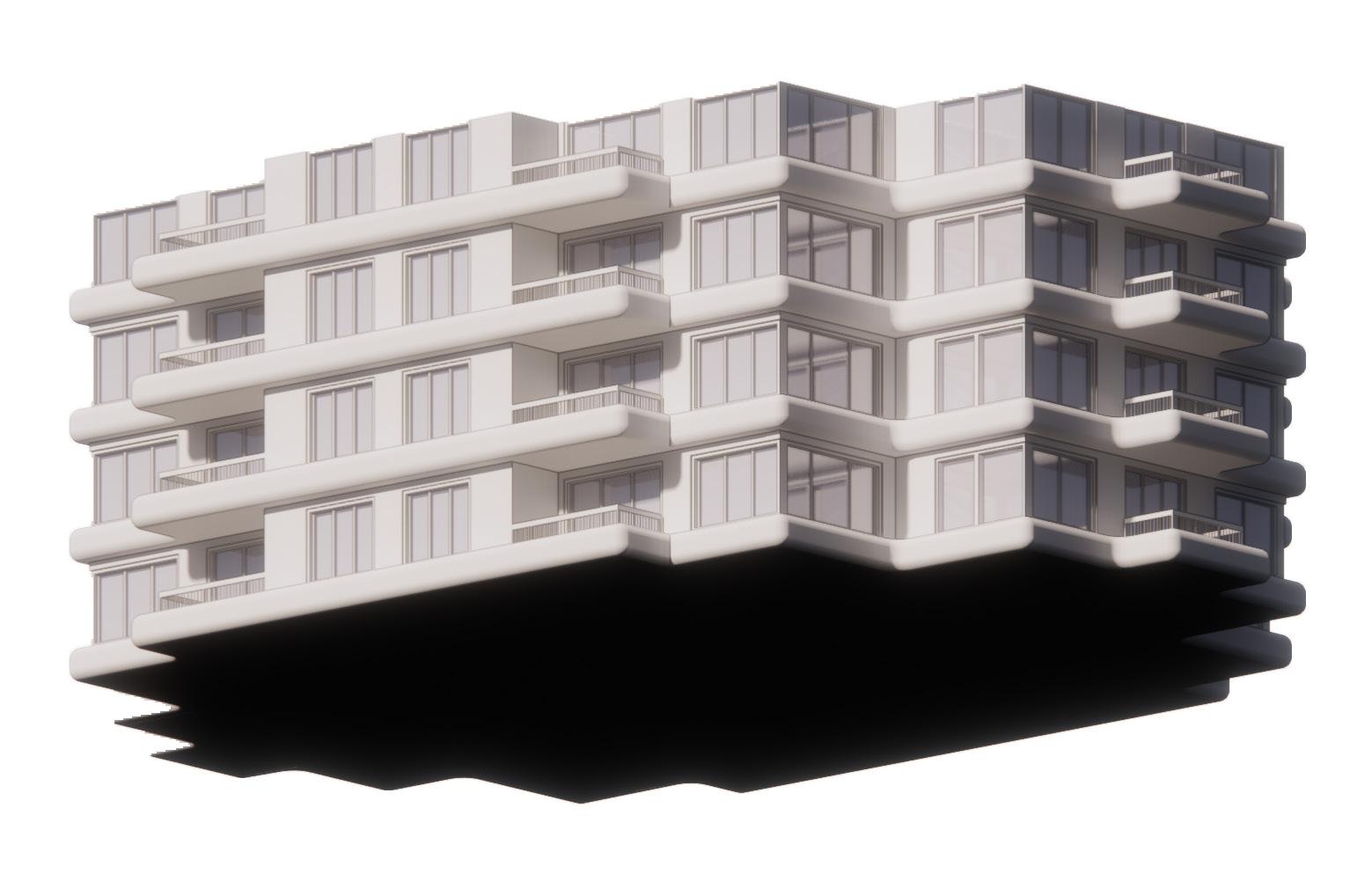
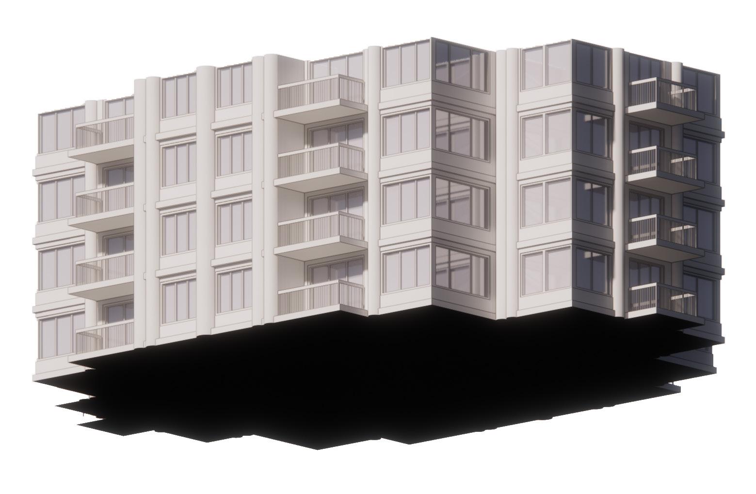
200 E 69th Street is a high-rise residential recladding project I worked on as an intern at Rogers Partners where I was able to participate in early conceptual design. The building was originally commissioned in the 1980’s with an art deco style in mind. I was initially tasked with creating a highly detailed 3D model of the existing building facades, and then was asked to produce diagrams analyzing the design patterns present within the existing building (such as the ways in which it tries and fails to relate to art deco style architecture). In addition, I also produced more zoomed in diagrams and modeling to show how the new building design strategy might relate (or contrast) what is existing currently. The design team wanted to take similar cues of art deco style architecture as what was existing (such as strong vertical elements), while also redefining the current building identity through exploring more modern and organic material options. The existing building is the tallest high rise in the upper east side and is visible from the entire area, but does not particularly have a strong architectural identity or stand out in any positive/significant way. With this, the design team wanted to use visual elements to enrich the experience of all who interact with the building, rather than just impacting the experience of only those who live in the building (which is how it currently is). One major design constraint is that the recladding must be done while residents still live within it, posing major questions as to how parts can be assembled and constructed without disruption to those inside.
New York, New York
Client: I.T. Palace Real Estate Corp.
Typology: Residential High Rise Recladding
Project Phase: Conceptual Design
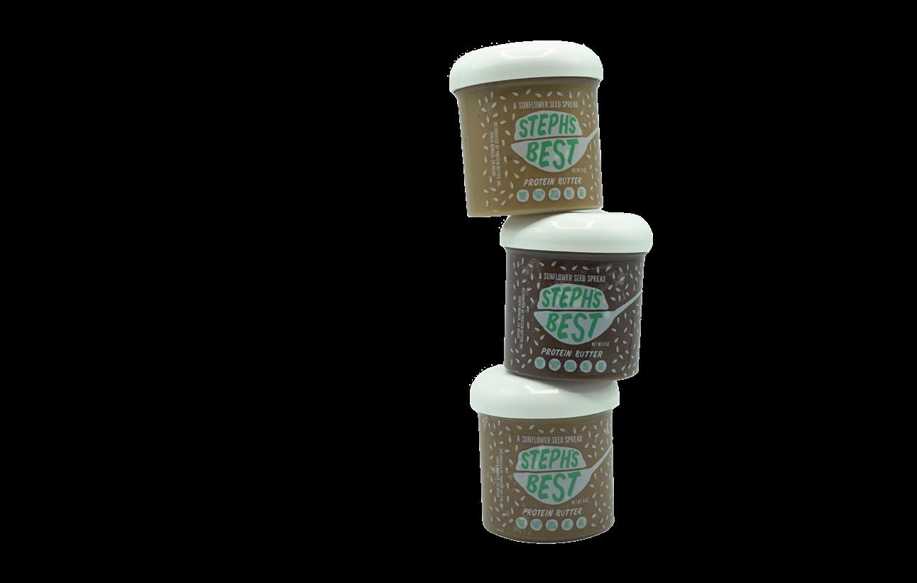
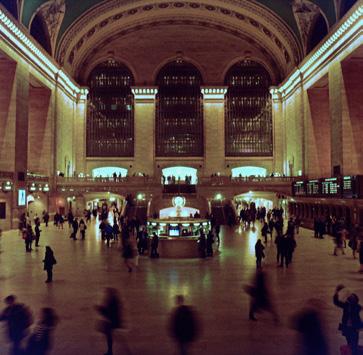
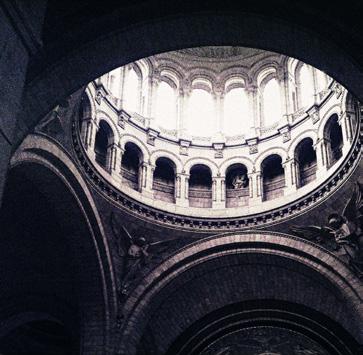
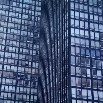
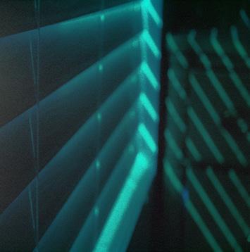
During my time working at DJNR Interactive, I got to build my graohic design skills, specifically through website and logo design for varying brands. Working with women owned buisnesses, I got to work on product design in creating branding labels and banners for a protein butter brand (‘Steph’s Best‘, as pictured below), and website design of a lifestyle brand (‘Higher Vibrations’, shown to the right). Through these specific projects, I not only improved my interpersonal communication skills with clients, but also developed knowledge in regards to project process from initial sketches to end design. In addition, I have always had a passion for film and digital photography, focusing mainly on architectural photography and on capturing unique light/shadow qualities of a certain space or object.


UT Austin School of Architecture design student who is interested in how architecture can promote a sustainable relationship to nature within urban environments, while also being focused on the human experience. Through past experience with projects that are focused on lessening community impact through the development of site-specific solutions, she believes that architecture must be inclusive to solve urban problems. With this, she strives to contribute meaningfully to her community through an emphasis on research in order to achieve conscious and thoughtful design.
University of Texas at Austin
Fourth Year B. Arch Major, Business Minor
3.69 GPA
McKinney High School
Graduated the Top 4% of the Class
UTSOA Design Excellence Nominee
UTSOA Design Excellence Winner
University Honors
Fall 2020, Spring 2022
Spring 2022
Spring 2019-Present
McKinney Education Foundation Scholarship Spring 2018
Digital Skills: Adobe Photoshop, Adobe Indesign, Adobe Illustrator, Adobe Lightroom, AutoCAD, Rhino (+ Grasshopper), Revit, SketchUp, 3DSMax, Enscape Renderer, ArcGIS
Alpha Rho Chi Professional Fraternity (Graphic Design Chair)
Sep 2020-May 2021
Developed all digital graphics for events and marketing
Prepared customizable graphics as incentives for fundraising events
Designed graphics to be advertised and distributed throughout the school
DJNR Interactive
(Graphic Design Intern; Austin, TX)
Sep 2020-May 2021
Designed logos, websites, social media posts and other branding elements for clients
Worked with clients directly and was responsible for client communication throughout the course of projects Collaborated with colleagues of different disciplines and helped to set project timelines
Rogers Partners (Architectural Intern; New York, NY)
June 2022-Dec 2022
Engaged in early conceptual design discussions and helped define project scope of services. Prepared request for proposal documents and developed diagrams to showcase project design intent. Performed site analysis for varying projects and used diagrammatic intervention to explore site design opportunities as well as floor plan organization. Reviewed submittals and worked on eggress documentation for projects during construction.