AIR SYSTEM PIPING GUIDE
CONSIDERATIONS AND INSTALLATION TIPS FOR COMPRESSED AIR DISTRIBUTION SYSTEMS

CONSIDERATIONS AND INSTALLATION TIPS FOR COMPRESSED AIR DISTRIBUTION SYSTEMS
If compressed air is the lifeblood of a plant, then the piping is the veins and arteries that carry it to each point of use. While it is absolutely essential for a compressed air system to function, piping is often overlooked during optimization projects and it’s also one of the first project costs cut when an installation budget needs trimming. Truth be told, piping material selection greatly impacts pressure drop, air quality, and leak load. Whether you are installing a brand new system or are considering upgrades to an existing one, this e-book will assist you in identifying the best piping materials for your application and also give you installation and maintenance tips to give you the best performance possible.
For the purposes of this e-book, it’s assumed you have already identified the pressure, flow and air quality requirements of your system. If you are unsure, we strongly recommend you contact a compressed air system expert for help determining these system parameters.
This e-book should be used as a supplement to any service manuals with your compressed air equipment or piping materials.
Diagrams in this e-book are presented only as examples. They are not necessarily the best way of installing your particular system.
If you need assistance, consult your local authorized Kaeser representative for expertise in installing your piping system.
Throughout the e-book, there are boxes with efficiency tips and additional resources. The links included in those will take you directly to more information that our engineers and piping experts have selected specifically to further assist with your piping system.

Pressure drop is the reduction in pressure from the compressor discharge to points-ofuse While it is best practice to reduce pressure drop as much as possible, it is not possible to eliminate it completely. A well-designed system should not have a pressure drop of more than 10% from the compressor discharge to the farthest point in the distribution piping.
Pressure drop occurs as the compressed air travels to the point-of-use through compressors, filters, dryers, piping, and all fittings and valves in between Any kind of obstruction will result in a loss of pressure
While pressure drop is to be expected, having excessive pressure drop can lead to poor system performance and higher energy consumption. Flow restrictions require higher system pressure to overcome the restriction, causing higher than necessary energy consumption As a matter of fact, every 2-psi increase causes approximately a 1% increase in compressor power Since a compressed air system is quite often the highest electrical consumer in a plant, properly controlling pressure drop can offer significant savings opportunities
When pressure drops at the point-of-use, the common reaction is to increase the pressure at the compressor. Unfortunately, this does nothing to address the root cause of the pressure drop.
At higher pressures, leaks will leak more and other forms of artificial demand (e.g. blowoff, sweeping) will waste more compressed air. Instead of turning up the pressure, take a look at your system and see why there is an issue
For example, if you notice there are periods of time with intermittent demand meaning periods of time when you need more air for a specific part of your process look at adding storage to your system so you’ll have extra air to supply that demand event
If tools are under-pressurized, check the size of the line. Many times plants will add on tools as their process demand increases, but they never increase the size of the line. It is also possible that instead of piping, point-of-use distribution is completely hose These are common causes of pressure drop that can easily be fixed
Finally, if you have multiple compressors that are short cycling ramping up and down this can be because they are not properly controlled In this case, add a master controller that can monitor your system demand and select the most efficient combination to meet it However, if the short cycling is due to insufficient piping or excessive pressure drop in the compressor room, addressing these issues first can provide significant operational benefits.
Fix the problem instead of raising the pressure
A large component of reducing compressed air system energy costs and increasing plant efficiency is choosing the right air distribution system Here’s an overview of common piping materials and some considerations to keep in mind when selecting pipe for your installation

For those types of pipe subject to corrosion, over time rust and scale deposits can build up.
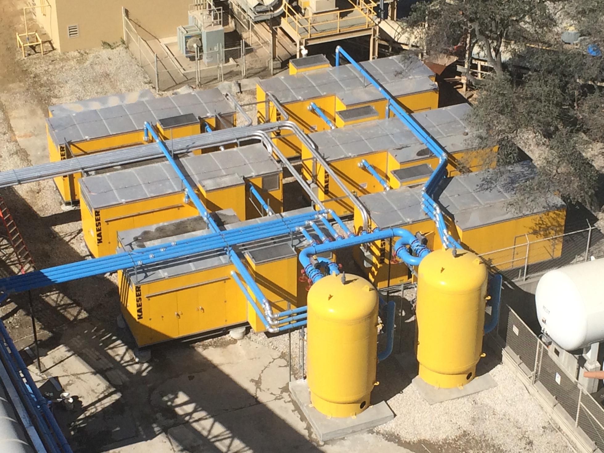
Choose piping materials based on operating temperature and pressure of the compressed air Keep in mind that compressed air can be contaminated with water, particulate, and oil Therefore the piping must not deteriorate with the presence of these contaminants (as in the picture above)
The most common piping materials include stainless steel, aluminum, copper, galvanized iron, black iron, and PVC. The table on the next page lists the advantages and disadvantages of each. PVC is included in the chart because it’s commonly used, but it’s not a material we would recommend because of the safety concerns associated with installing it, as OSHA has stated that PVC is not safe for use in compressed air systems
Generally speaking, aluminum and copper would be the best choices since they are not prone to build-up and will provide years of low pressure drop air delivery Also, aluminum is available as a system complete with perfectly matched connectors for leak-free design
Copper is also a solid choice, however installation does require an open flame and quality brazing to prevent leaks. The material cost can also be high.
Stainless steel is not prone to build up or leaks, but it is very expensive and really only called for in specialty applications if you need it, you’ll know
Black iron
Moderate material costs
Readily available in multiple sizes
Copper
Moderate material costs
Readily available in multiple sizes
Some rust protection
No rust, good air quality
Smooth interior - low pressure drop
Stainless steel No rust, good air quality
Smooth interior - low pressure drop
Labor-intensive installation
May rust and leak
Rough inside promotes contaminants to build up and creates pressure drop
Often exterior is coated
Labor-intensive installation
May rust at joints and leak
Rough inside promotes contaminants to build up and creates pressure drop
Requires quality brazing to prevent leaks
Susceptible to thermal cycling
Installation requires open flame
Labor intensible installation
Expensive materials
PVC
Lightweight
Inexpensive
Aluminum
Corrosion resistant
Lightweight
Easy to install
Lower cost of ownership
Not recommended for compressed air
Lower safety
May not be code-compliant
Subject to bursting
Adhesives not compatible with compressor oils
Limited pressure ratings
Material costs


Right:pittingonthesamealuminumpipeaftercleaning
Most compressed air systems are a hybrid of new and old. In these cases, piping connections can be made simply by putting two joints together, flanged or threaded However, when it comes to chemical composition, connecting aluminum directly to brass or copper can cause a chemical reaction called galvanic corrosion Over time any water present (such as condensate) will serve as a conductor, shedding electrons from one material to another This can cause pitting corrosion, even in your new aluminum piping
How to avoid galvanic corrosion in aluminum piping:
Don’t connect your aluminum directly to copper or brass; connect it to steel piping (but not stainless steel)
Add a drip leg with a no-loss demand drain at the discharge of the compressor; get the condensate out of the system!
Alternative to the drip leg, if your compressor does not have an internal centrifugal separator (with drain), add them at the discharge to the compressor Slope the compressor discharge piping so that any condensate runs downhill and doesn’t have an opportunity to pool in the piping.
To avoid pitting avoid angles and pockets in which water can accumulate. Use shapes that promote draining (i e sloping the pipe, don’t install piping in a U)
Read our blog post for more on galvanic corrosion.
All piping materials experience thermal expansion some materials more than others. If thermal expansion and contraction is not compensated for in the system design, it can have long-term, damaging effects. Leaks from stressing threads and soldered points and compromised couplings are just a few examples
Expansion hoses and anti-whiplash straps can be installed to help compensate Any time temperature changes from area to area consider adding an expansion hose, as well as at the compressor discharge For specific guidance, contact your piping manufacturer or supplier


When selecting piping for an installation, consider the following:
Material cost: Will you need to purchase special tools to install or maintain the pipe?
Installation: Will you need to outsource? Also, do you anticipate growth or making changes to your piping? (Aluminum pipe can be disassembled easily and adding in drops to accommodate growth is fast Copper is not as quick to install as aluminum, but it is still faster than threaded pipe)
Air quality: Can your process tolerate contamination from rust or other build-up flaking off from the pipe? (Black iron and galvanized iron are notorious for this)
Maintenance: Do you have the time and manpower to continually monitor and fix leaks that can occur with materials that are more susceptible to rusting at joints and leaking? (A concern for black iron and galvanized iron. Also, the brazing on copper should be inspected regularly).

Safety: We recommend that when our technicians find a system with PVC or other piping not rated for compressed air that they complete a safety observation form and instruct the customer and then perform the service (or start-up) once they have addressed the safety issue
When it’s time to choose piping materials, look at more than the cost of the pipe. Think about your system needs today and long term. Looking ahead can help you make the right investment at the right time
Read our blog post for more tips on material selection.
There are three main types of piping network distribution design: ring (or looped), branch, and combination With a ring pipe network, it’s possible to use smaller diameter piping and the overall ring can be sized roughly for half of the flow volume and length To address possible problems with pressure fluctuations we recommend using point-of-use storage and metered supply valves to ensure stable plant pressure throughout the network

A branch pipe network require less pipework than a ring, but they need a larger piping diameter comparatively. If pressure drop becomes problematic, they can be expanded into a combination pipe network

The combination pipe network offers the best of both piping network designs The piping diameter can be smaller (thanks to the ring) and it’s still easy to isolate sections of piping with strategically placed valves In determining the size for the main header, look to the future and make sure it’s sized adequately enough for future expansion This will reduce the likelihood of future pressure drop issues and save you time, money, and headaches down the road.

For systems without a dryer, most of the condensate occurs in the distribution network. To prevent condensate build-up, the line should slope downward at least 2° and include a condensate drain at the lowest point. Any point-of-use applications should be connected to the main line with a swan neck, to keep the condensate in the main line.
If you are connecting one or more compressors that don’t include an integrated moisture separator, they should be connected with a swan neck as well to prevent condensate from back-flowing to the compressor
Use automatic condensate drains to prevent compressed air loss.

Systems with a dryer do not need to have a slope in the piping. It is important to pipe the points-of-use so the outlet is at the top (swan neck). This prevents condensate from damaging any air consumers should the refrigerated dryer fail.
As with the previous example, if you are connecting one or more compressors that don’t include an integrated moisture separator, they should be connected with a swan neck as well to prevent condensate from back-flowing to the compressor
The after-filter and components, including piping, fittings, seals, etc downstream of a heated desiccant dryer, must be rated for 400°F (204°C).
Another key factor in pipe design is velocity The velocity of compressed air in piping has a number of effects:
Pressure drop The higher the velocity, the greater the pressure drop. This is because air molecules are colliding with the pipe walls more often, creating friction and upsetting good laminar flow.
Reduced air quality High air velocity reduces contact time in dryers, and they may not dry the air to specification
The result is moisture in tools and equipment Further, high velocities can tear filters and allow particulate through In both cases, equipment may require more maintenance or have more downtime, and there is increased risk of product contamination.
Loosening pipe rust and scale In iron piping, rust and scale may be carried downstream, clogging compressed air filters at the point of use and impacting production equipment Over time, this may erode the pipe walls, leading to leaks
Noise and vibration Increased turbulence may cause piping and pneumatics to vibrate and chatter This could even lead to loose fittings including at points of use
The ideal velocity for compressed air piping depends on a number of factors, including the length of the piping, and the pressure requirements. We recommend minimizing the compressed air velocity in the compressor room to 15 feet per second In the main distribution header the velocity should be 30 feet per second, and in the point-of-use piping the velocity should be a maximum of 45 feet per second
Here are some additional tips for minimizing the effects of velocity on compressed air piping:
Use the correct pipe size. The larger the pipe diameter, the lower the velocity will be. The CAGI Handbook has a good guide for pipe sizing based on pressure and flow.
Apply controls to multiple compressors If multiple compressors feed the same pipe but don’t have a common controller, they may unnecessarily come online at the same time and deliver excess flow, increasing velocity and wasting power
Apply flow controls Flow controls between the supply side and demand side can be used to pressurize the downstream piping more smoothly to prevent high velocities that overrun dryers and damage filters, especially during periods when the system is being pressurized after being off. Flow controls can also be used to isolate intermittent high flow uses from the rest of the system.
Find and eliminate leaks to reduce demand (and therefore flow). For the same reason, replace timed condensate drains with reliable no-loss demand drains on all moisture collection points to reduce air demand
A single, small hole that is 1/4” in diameter costs you approximately $1,246 every month (at 90 psig)
Compressed air systems have leaks. Some are present from the time of installation while others develop over time. Regardless of the source, they can greatly reduce operating effectiveness and cost a lot in energy The U S Department of Energy estimates that as much as 25% of compressed air is lost to leaks - and it's higher in many plants
Kaeser recommends a post-installation leak check as well as periodic leak detection checks Upon commissioning, the system can be checked for leaks by simply charging the system with air and not using air If the compressor cycles on to recharge the system or if the pressure drops at the storage tank, there are leaks.
We recommend annual leak audits to identify and fix leaks that develop over time.
The chart below shows how much even a single leak can cost you year after year An annual leak detection plan can help you stay ahead of the game
Annual leak cost based on 8,760 operating hours and $0.10 kW/h. See Appendix B for more information.

There are three main methods for leak detection: listen and feel, soapy water, and ultrasonic Listen and feel is exactly what it sounds like walking the length of the piping, listening for hissing leaks, and then touching the pipe to help locate the leak This approach is simple and straightforward for finding large leaks As it does require direct physical contact with the piping, it may not be practical nor would it be the safest.
Using the soapy water method involves applying a soapy mixture to the areas suspected of leaking and waiting for bubbles to form This is also simple and reliable, yet time consuming Like the listen and feel method, it requires direct contact with the piping and neither can give any information on the volume of the leak
The industry standard is ultrasonic leak detection While this method requires special equipment and some training, it is fast and accurate. It can even detect leaks as small as a pinhole. Perhaps the biggest benefit for this method is that it can provide the volume of the leak and calculate how much money is being lost to each one. This can be helpful in prioritizing which leaks to fix first
The chart on the next page compares each leak detection method
Listen and feel
Soapy water
Ultrasonic Simple
Quickly identifies large leaks No special tools requireds
Only effective for large leaks
Requires direct physical contact
Must be able to hear above the plant equipment
Will not work for most leaks
Give no information on leak volume
Reliable Simple No special tools required
Time consuming Requires direct physical contact
Give no information on leak volume
Versatile
Can detect leaks as smsall as a pinhole Fast and accurate Does not require plant downtime Does not require physical contact
Requires special equipment
Contact your local authorized Kaeser representative for assistance obtaining leak savings information for other pressures.
The following pages include formulas and instructions for common calculations associated with piping
Use our Kaeser Toolbox, which includes online calculators and other helpful tips.

To calculate pressure drop, you’ll need to know the pressure drop due to friction, pipe diameter, length of pipe, initial pressure, and flow rate of the system
For the below example, we’ll use the pressure drop due to friction at 100 psig chart (below).
Formula:
Piping Pressure Drop =
Pressure drop due to friction x System Pipe Length (ft ) x (Pressure + 14 5)
Pipe Length x (Initial Pressure + 14.5)
Example:
What is the pressure drop in a 2-inch pipe, 350 feet in length, with an initial pressure of 85 psig, and a flow rate of 500 cfm of free air?
19 2 x 350 (ft ) x (100 + 14 5) = 7 73 psi
1,000 (ft ) x (85 + 14 5)
In this example, 7.73 psi is 10% of the generation pressure; we would recommend going up a size for your piping

ChartcourtesyofCompressedAirandGas Institute(CAGI).
You can measure your system’s total leak load using the pressure gauge on your air receiver. In order for this approach to be effective, you need to have an estimate of the total system volume (V) which would include all downstream air receivers, air mains, and piping (in cfm).
The system is started and brought up to operating pressure (P1) Then, you measure the time it takes (T) for the system to drop to a lower pressure (P2) This point should be approximately one-half of the operating pressure
It’s a good idea to take several time measurements and then average them
Leakage (cfm) = [V x (P1 - P2)] / [(T x 14.7) x 1.25]
The 1 25 multiplier is used to allow for reduced leakage with falling system pressure

Compressor run times can also be used to measure leak load. This method can be applied for a complete compressed air system or a section of the distribution network, providing it can be isolated
For this method, all compressed air users are off and the compressor is started Then, the time it takes for the compressor to load and unload is measured This is done several times to get a good average length of time
Leakage (%) = [(T x 100) / (T + t)]
t = off-load time (minutes)
T = on-load time (minutes)
Note that many downstream users are constant users of compressed air, whether they are running or not Therefore, it may be advantageous to add a solenoid valve to close the compressed air supply and only run compressed air to the equipment when it is required

The piping installation should be conducted in a safe manner in accordance with OSHA and appropriate local regulations
Before doing any work on a piping distribution system, the system should be de-pressurized. If working on a particular section of the system, that part of the system should be isolated from the main and de-pressurized
When working in a lift, technicians should use a proper harness and rigging
The piping distribution system must be installed so that normal operation poses no threat to work health or safety.
Follow OSHA recommendations for electrical lock-out/tag-out and compressed air blow-down precautions
Follow all safety recommenda manufacturer’s service manua
Compressed air can provide significant forces Always wear the proper PPE when working in a compressed air system

Looking for more information on piping and compressed air topics? Check out the following resources:
us.kaeser.com/blog
Our company blog posts on a wide range of compressed air topics written by our subject matter experts and is updated regularly You can also sign up to follow the blog to receive updates whenever there is a new blog post
us kaeser com/resources
This page has a collection of technical articles, safety data sheets (SDS), tools, and more
us kaeser com/whitepapers

Don't forget about the Kaeser Toolbox, which includes online calculators and other helpful tips
ChartstakenfromtheCompressedAirandGasHandbook Visitwwwcagiorgformoreinformation


CharttakenfromtheCompressedAirandGasHandbook.Visitwww.cagi.orgformoreinformation.


NEILMEHLTRETTER TECHNICALDIRECTOR

BILLKEMPH,JR.
ENGINEEREDSOLUTIONS PROJECTMANAGER

MICHAELCAMBER MARKETINGSERVICES MANAGER
At KAESER, we believe the more you know about proper system design and operation, the more you’ll get out of it. That’s why we are committed to offering you the most current information you need to wisely install, operate, and maintain yours. This e-book was written for you by Kaeser’s piping and system design experts
Your piping is a key part of your compressed air system and how it is installed and maintained will impact your overall system’s efficiency for years to come The goal of this e-book is to help you select the right materials, install them safely, and maintain them properly for a safe, efficient, and long-lasting compressed air distribution system.
We recognize that each system and application is unique, but applying the principles you read here is an excellent place to start For the best in system optimization that is tailored to your needs, contact us for additional support

We earn our customers’ business by supplying superior quality equipment and services Our products are designed for reliable performance, easy maintenance, and energy efficiency Prompt and dependable customer service, quality assurance, training, and engineering support contribute to the value our customers have come to expect from KAESER. Our employees are committed to implementing and maintaining the highest standards of quality to merit customer satisfaction. We aim for excellence in everything we do
Kaeser Compressors, Inc
511 Sigma Drive
Fredericksburg, Virginia 22408 USA
Phone: 540-898-5500
Toll Free: 800-777-7873
Email: info.usa@kaeser.com


Copyright©2023KaeserCompressors,Inc

