
6904146 (5-08) Printed in U.S.A.© Bobcat Company 2008 Service Manual T190 Track Loader S/N 531611001 - 531659999 S/N 531711001 - 531759999 EQUIPPED WITH BOBCAT INTERLOCK CONTROL SYSTEM (BICS)

Instructions are necessary before operating or servicing machine. Read and understand the Operation & Maintenance Manual, Operator’s Handbook and signs (decals) on machine. Follow warnings and instructions in the manuals when making repairs, adjustments or servicing. Check for correct function after adjustments, repairs or service. Untrained operators and failure to follow instructions can cause injury or death.
Safety Alert Symbol: This symbol with a warning statement, means: “Warning, be alert! Your safety is involved!” Carefully read the message that follows.
Never service the Bobcat Compact Track Loader without instructions.
WRONG
Use the correct procedure to lift or lower operator cab.
WRONG
WRONG
Have good ventilation when welding or grinding painted parts.
Wear dust mask when grinding painted parts. Toxic dust and gas can be produced. Avoid exhaust fume leaks which can kill without warning. Exhaust system must be tightly sealed.
WRONG B-15955
Stop, cool and clean engine of flammable materials before checking fluids.
Never service or adjust loader with the engine running unless instructed to do so in the manual.
Avoid contact with leaking hydraulic fluid or diesel fuel under pressure. It can penetrate the skin or eyes.
Never fill fuel tank with engine running, while smoking or when near open flame.
Disconnecting or loosening any hydraulic tubeline, hose, fitting, component or a part failure can cause lift arms to drop. Do not go under lift arms when raised unless supported by an approved lift arm support device. Replace it if damaged.
Never work on loader with lift arms up unless lift arms are held by an approved lift arm support device. Replace if damaged. Never modify equipment or add attachments not approved by Bobcat Company.
WRONG WRONG
Keep body, jewelry and clothing away from moving parts, electrical contact, hot parts and exhaust.
Wear eye protection to guard from battery acid, compressed springs, fluids under pressure and flying debris when engines are running or tools are used. Use eye protection approved for type of welding. Keep rear door closed except for service, Close and latch door before operating the loader.
Lead-acid batteries produce flammable and explosive gases. Keep arcs, sparks, flames and lighted tobacco away from batteries. Batteries contain acid which burns eyes or skin on contact. Wear protective clothing. If acid contacts body, flush well with water. For eye contact flush well and get immediate medical attention.
Maintenance procedures which are given in the Operation & Maintenance Manual can be performed by the owner/ operator without any specific technical training. Maintenance procedures which are not in the Operation & Maintenance Manual must be performed ONLY BY QUALIFIED BOBCAT SERVICE PERSONNEL. Always use genuine Bobcat replacement parts. The Service Safety Training Course is available from your Bobcat dealer.
Instructions are necessary before operating or servicing machine. Read and understand the Operation & Maintenance Manual, Operator’s Handbook and signs (decals) on machine. Follow warnings and instructions in the manuals when making repairs, adjustments or servicing. Check for correct function after adjustments, repairs or service. Untrained operators and failure to follow instructions can cause injury or death. W-2003-0903
Safety Alert Symbol: This symbol with a warning statement, means: “Warning, be alert! Your safety is involved!” Carefully read the message that follows.
Never service the Bobcat Compact Track Loader without instructions.
WRONG
Have good ventilation when welding or grinding painted parts.
Wear dust mask when grinding painted parts. Toxic dust and gas can be produced. Avoid exhaust fume leaks which can kill without warning. Exhaust system must be tightly sealed.
WRONG
Use the correct procedure to lift or lower operator cab.
WRONG
Disconnecting or loosening any hydraulic tubeline, hose, fitting, component or a part failure can cause lift arms to drop. Do not go under lift arms when raised unless supported by an approved lift arm support device. Replace it if damaged.
Cleaning and maintenance are required daily.
WRONG
Never work on loader with lift arms up unless lift arms are held by an approved lift arm support device. Replace if damaged. Never modify equipment or add attachments not approved by Bobcat Company.
WRONG
Stop, cool and clean engine of flammable materials before checking fluids.
Never service or adjust loader with the engine running unless instructed to do so in the manual.
Avoid contact with leaking hydraulic fluid or diesel fuel under pressure. It can penetrate the skin or eyes.
Never fill fuel tank with engine running, while smoking or when near open flame.
Keep body, jewelry and clothing away from moving parts, electrical contact, hot parts and exhaust.
Wear eye protection to guard from battery acid, compressed springs, fluids under pressure and flying debris when engines are running or tools are used. Use eye protection approved for type of welding. Keep rear door closed except for service, Close and latch door before operating the loader.
Lead-acid batteries produce flammable and explosive gases. Keep arcs, sparks, flames and lighted tobacco away from batteries. Batteries contain acid which burns eyes or skin on contact. Wear protective clothing. If acid contacts body, flush well with water. For eye contact flush well and get immediate medical attention.
Maintenance procedures which are given in the Operation & Maintenance Manual can be performed by the owner/ operator without any specific technical training. Maintenance procedures which are not in the Operation & Maintenance Manual must be performed ONLY BY QUALIFIED BOBCAT SERVICE PERSONNEL. Always use genuine Bobcat replacement parts. The Service Safety Training Course is available from your Bobcat dealer.
CYLINDER (TILT)................................................20-01
CYLINDER HEAD...................................................70-01
FILTERS..................20-01
HYDRAULIC/HYDROSTATIC SYSTEM..................10-01
HYDRAULIC PUMP (STANDARD)..........................20-01
HYDRAULIC PUMP (STANDARD) (HIGH FLOW)..20-01
HYDRAULIC PUMP (SJC) (HIGH FLOW)...............20-01
HYDARULIC PUMP (SJC)......................................20-01
HYDRAULIC SYSTEM INFORMATION..................20-01
HYDROSTATIC MOTOR.....................................30-01
HYDROSTATIC MOTOR CARRIER........................30-01
HYDROSTATIC PUMP........................................30-01
HYDROSTATIC PUMP (SJC).............................30-01
HYDROSTATIC SYSTEM INFORMATION..........30-01
INSTRUMENT PANELS..........................................60-01
LIFT ARMS..............................................................50-01
LIFT ARM BYPASS CONTROL VALVE..............20-01
LIFT ARM SUPPORT DEVICE...........................10-01
LIFTING AND BLOCKING THE LOADER...............10-01
LIGHTS................................................................60-01
LOADER SPECIFICATIONS.............................SPEC-01
LOADER STORAGE AND RETURN TO SERVICE10-01
LUBRICATING THE LOADER.................................10-01
LUBRICATION SYSTEM.........................................70-01
MAIN RELIEF VALVE..............................................20-01
MAINTENANCE CLOCK.........................................60-01
MUFFLER................................................................70-01
OIL COOLER...........................................................20-01
OPERATOR CAB.........................................10-01, 50-01
OPERATOR SEAT (SUSPENSION)........................50-01
PASSWORD SETUP (IF EQUIPPED WITH KEYLESS START).................................................60-01
PIVOT PINS............................................................10-01
POWER BOB-TACH (OPTION)....................10-01, 50-01
POWER BOB-TACH BLOCK...................................20-01
PRESSURE RELIEF VALVE...................................80-01
PRESSURE SWITCH..............................................80-01
This manual is for the Bobcat loader mechanic. It provides necessary servicing and adjustment procedures for the Bobcat loader and its component parts and systems. Refer to the Operation & Maintenance Manual for operating instructions, starting procedure, daily checks, etc.
A general inspection of the following items must be made after the loader has had service or repair:
1.Check that the ROPS/FOPS (Including side screens) is in good condition and is not modified.
2.Check that ROPS mounting hardware is tightened and is Bobcat approved.
9.The parking brake must function correctly.
10.Enclosure door latches must open and close freely.
3.The seat belt must be correctly installed, functional and in good condition.
4.The seat bar must be correctly adjusted, clean and lubricated.
11.Bob-Tach wedges and linkages must function correctly and be in good condition.
12.Safety treads must be in good condition.
5.Check lift arm support device, replace if damaged.
13.Check for correct function of indicator lamps (Optional on some models).
6.Machine signs must be legible and in the correct location.
14.Check hydraulic fluid level, engine oil level and fuel supply.
7.Steering levers and foot pedals must return to neutral.
15.Inspect for fuel, oil or hydraulic fluid leaks.
8.Check for correct function of the work lights
16.Lubricate the loader.
17.Check the condition of the battery and cables.
22.Operate the loader and check all functions.
18.Inspect the air cleaner for damage or leaks. Check the condition of the element.

23.Check for any field modification not completed.
19.Check the electrical charging system.
24.Check for correct function of the Bobcat Interlock Control System (BICS) before the machine is returned to the customer.

20.Check tracks for wear and tension.
25.Recommend to the owner that all necessary corrections be made before the machine is returned to service.
21.Inspect for loose or broken parts or connections.
Diesel engine exhaust and some of its constituents are known to the State of California to cause cancer, birth defects and other reproductive harm.
This symbol with a warning statement means: “Warning, be alert! Your safety is involved!” Carefully read the message that follows.
Instructions are necessary before operating or servicing machine. Read and understand the Operation & Maintenance Manual, Operator’s Handbook and signs (decals) on machine. Follow warnings and instructions in the manuals when making repairs, adjustments or servicing. Check for correct function after adjustments, repairs or service. Untrained operators and failure to follow instructions can cause injury or death.
W-2003-0903
Warnings on the machine and in the manuals are for your safety. Failure to obey warnings can cause injury or death.
W-2044-1285
This notice identifies procedures which must be followed to avoid damage to the machine.
I-2019-0284
The following publications provide information on the safe use and maintenance of the Bobcat machine and attachments:
•The Delivery Report is used to assure that complete instructions have been given to the new owner and that the machine is in safe operating condition.
•The Operation & Maintenance Manual delivered with the machine or attachment contains operating information as well as routine maintenance and service procedures. It is a part of the machine and can be stored in a container provided on the machine. Replacement Operation & Maintenance Manuals can be ordered from your Bobcat dealer.
•Machine signs (decals) instruct on the safe operation and care of your Bobcat machine or attachment. The signs and their locations are shown in the Operation & Maintenance Manual. Replacement signs are available from your Bobcat dealer.
•An Operator’s Handbook fastened to the operator cab. It’s brief instructions are convenient to the operator. The handbook is available from your dealer in an English edition or one of many other languages. See your Bobcat dealer for more information on translated versions.
•The AEM Safety Manual delivered with the machine gives general safety information.
•The Service Manual and Parts Manual are available from your dealer for use by mechanics to do shoptype service and repair work.
•The Skid-Steer Loader Operator Training Course is available through your local dealer or at www.training.bobcat.com or www.bobcat.com. This course is intended to provide rules and practices of correct operation of the Skid-Steer Loader. The course is available in English and Spanish versions.
•Service Safety Training Courses are available from your Bobcat dealer or at www.training.bobcat.com or www.bobcat.com. They provide information for safe and correct service procedures.
•The Skid-Steer Loader Safety Video is available from your Bobcat dealer or at www.training.bobcat.com or www.bobcat.com.
The machine and some attachments have components that are at high temperatures under normal operating conditions. The primary source of high temperatures is the engine and exhaust system. The electrical system, if damaged or incorrectly maintained, can be a source of arcs or sparks.
Flammable debris (leaves, straw, etc.) must be removed regularly. If flammable debris is allowed to accumulate, it can cause a fire hazard. Clean often to avoid this accumulation. Flammable debris in the engine compartment is a potential fire hazard.
The operator’s area, engine compartment and engine cooling system must be inspected every day and cleaned if necessary to prevent fire hazards and overheating.
All fuels, most lubricants and some coolants mixtures are flammable. Flammable fluids that are leaking or spilled onto hot surfaces or onto electrical components can cause a fire.
Do not use the machine where exhaust, arcs, sparks or hot components can contact flammable material, explosive dust or gases.


Check hydraulic tubes, hoses and fittings for damage and leakage. Never use open flame or bare skin to check for leaks. Hydraulic tubes and hoses must be properly routed and have adequate support and secure clamps. Tighten or replace any parts that show leakage.
Always clean fluid spills. Do not use gasoline or diesel fuel for cleaning parts. Use commercial nonflammable solvents.
Check all electrical wiring and connections for damage. Keep the battery terminals clean and tight. Repair or replace any damaged part or wires that are loose or frayed.
Battery gas can explode and cause serious injury. Use the procedure in the Operation & Maintenance Manual for connecting the battery and for jump staring. Do not jump start or charge a frozen or damaged battery. Keep any open flames or sparks away from batteries. Do not smoke in battery charging area.
Stop the engine and let it cool before adding fuel. No smoking! Do not refuel a machine near open flames or sparks. Fill the fuel tank outdoors.
Do not use ether or starting fluids on any engine that has glow plugs. These starting aids can cause explosion and injure you or bystanders.

Use the procedure in the Operation & Maintenance Manual for connecting the battery and for jump starting.
The spark arrestor exhaust system is designed to control the emission of hot particles from the engine and exhaust system, but the muffler and the exhaust gases are still hot.
Check the spark arrestor exhaust system regularly to make sure it is maintained and working properly. Use the procedure in the Operation & Maintenance Manual for cleaning the spark arrestor muffler (if equipped).
Always clean the machine and attachment, disconnect the battery, and disconnect the wiring from the Bobcat controllers before welding. Cover rubber hoses, battery and all other flammable parts. Keep a fire extinguisher near the machine when welding.
Have good ventilation when grinding or welding painted parts. Wear dust mask when grinding painted parts. Toxic dust or gas can be produced.
Dust generated from repairing nonmetallic parts such as hoods, fenders or covers can be flammable or explosive. Repair such components in a well ventilated area away from open flames or sparks.
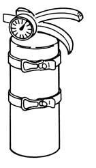
Know where fire extinguishers and first aid kits are located and how to use them. Inspect the fire extinguisher and service the fire extinguisher regularly. Obey the recommendations on the instructions plate.
Always use the serial number of the loader when requesting service information or when ordering parts. Early or later models (identification made by serial number) may use different parts, or it may be necessary to use a different procedure in doing a specific service operation.
Loader Serial Number

Figure 1
Explanation of loader Serial Number:
XXXXXXXXX
Engine Serial Number

The Delivery Report must be filled out by the dealer and signed by the owner or operator when the Bobcat loader is delivered. An explanation of the form must be given to the owner. Make sure it is filled out completely [Figure 3]

SEAT BAR LEVER STEERING
TILT CYLINDER
† BUCKET
FRONT LIGHTS
GRAB HANDLES
OPERATOR SEAT WITH SEAT BELT
▼ REAR AUXILIARY QUICK COUPLERS
STABILIZER ROD
FRONT AUXILIARY QUICK COUPLERS
BUCKET STEPS
LIFT ARM LINK
REAR GRILL
REAR WINDOW
SAFETY TREAD
● OPERATOR CAB (ROPS & FOPS)

LIFT ARM
LIFT CYLINDER
TAIL LIGHT
REAR LIGHT
REAR DOOR
▼ OPTIONAL OR FIELD ACCESSORY (Not Standard Equipment)
❒ TRACKS - Optional tracks are available.
LIFT ARM SUPPORT DEVICE
❒ TRACKS
† Bucket - Several different buckets and other attachments are available for this machine.
B-15984
B-15985A
● ROPS, FOPS - Roll Over Protective Structure, per SAE J1040 and ISO 3471, and Falling Object Protective Structure per ISO 3449, Level I. Level II is available. Extra insulated cab is available as an option (Reduced noise level).
TIGHTEN ALL HARDWARE PER SIZE TO GRADE 5 (SEE STANDARD TORQUE SPECIFICATIONS FOR BOLTS, SPEC-01 SECTION) TORQUE UNLESS OTHERWISE SPECIFIED.
Instructions are necessary before operating or servicing machine. Read and understand the Operation & Maintenance Manual, Operator’s Handbook and signs (decals) on machine. Follow warnings and instructions in the manuals when making repairs, adjustments or servicing. Check for correct function after adjustments, repairs or service. Untrained operators and failure to follow instructions can cause injury or death.
W-2003-0903
Always park the loader on a level surface.
Put floor jack under the rear of the loader [Figure 10-102]
Lift the rear of the loader and install jackstands [Figure 10-10-2]


Put jackstands under the front axles and rear corners of the frame before running the engine for service. Failure to use jackstands can allow the machine to fall or move and cause injury or death.

W-2017-0286
Lift the front of the loader and put jackstands under the axle tubes [Figure 10-10-3]
NOTE:Make sure the jackstands do not touch the tracks. Make sure the tracks clear the floor or any obstacles.
Never work on a machine with the lift arms up unless the lift arms are secured by an approved lift arm support device. Failure to use an approved lift arm support device can allow the lift arms or attachment to fall and cause injury or death.

Service lift arm support device if damaged or if parts are missing. Using a damaged lift arm support or with missing parts can cause lift arms to drop causing injury or death.

W-2572-0407
Put jackstands under the rear corners of the loader frame (Inset) [Figure 10-20-1]

Remove the lift arm support device (Item 1) [Figure 1020-1] from storage position.
The operator must be in the operator's seat, with the seat belt fastened and seat bar lowered, until the lift arm support device is installed.
Start the engine, and raise the lift arms all the way up.
Remove the attachment from the loader. (See BOBTACH (HAND LEVER) on Page 50-40-1.) OR (See BOBTACH (POWER-OPTION) on Page 50-41-1.)
Have a second person install the lift arm support device (Item 1) [Figure 10-20-2] over the rod of one of the lift cylinders.
The lift arm support device must be tight against the cylinder rod.

Installing (Cont’d)
Figure 10-20-3
Lower the lift arms slowly until the lift arm support device is held between the lift arms and the lift cylinder [Figure 10-20-3]. The tabs of the lift arm support device must go under the cylinder (Inset) [Figure 10-20-3].
The operator must be in the operator's seat, with the seat belt fastened and seat bar lowered, until the lift arm support device is removed and the lift arms are lowered all the way.

Start the engine, raise the lift arms all the way up.
Have a second person remove the lift arm support device.
Lower the lift arms all the way and stop the engine.
Return the lift arm support device to storage position and secure with clamping knobs.
Remove the jackstands.

The Bobcat Loader has an operator cab (ROPS and FOPS) as standard equipment to protect the operator from rollover and falling objects. Check with your dealer if the operator cab has been damaged. The seat belt must be worn for rollover protection.
ROPS / FOPS - Roll Over protective Structure per ISO 3471, and Falling Object Protective Structure per SAE J1043 and ISO 3449, Level I. Level II is available.
Level I
Protection from falling bricks, small concrete blocks, and hand tools encountered in operations such as highway maintenance, landscaping, and other construction sites.
Level
Protection from falling trees, rocks: for machines involved in site clearing, overhead demolition or forestry.
Never modify operator cab by welding, grinding, drilling holes or adding attachments unless instructed to do so by Bobcat Company. Changes to the cab can cause loss of operator protection from rollover and falling objects, and result in injury or death.
W-2069-0200
Raising
Always stop the engine before raising or lowering the cab.

Stop the loader on a level surface. Lower the lift arms. If the lift arms must be up while raising the operator cab, install the lift arm support device. (See Installing on Page 10-20-1.)

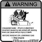

NOTE:On Advanced Control System (ACS) equipped machines, the steering levers could contact the cab frame while raising or lowering the operator cab. The engine MUST be stopped before raising or lowering the cab.
Remove

Always stop the engine before raising or lowering the cab.
NOTE:Always use the grab handles to lower the cab.
PINCH POINT CAN CAUSE INJURY
Remove your hand from the latching mechanism when the cab is past the latch stop.

W-2469-0803
NOTE:The weight of the cab increases when equipped with options and accessories such cab door, heater, air conditioning, etc. In these cases, the cab may need to be raised slightly from the latch to be able to release the latch.
Install the plates and nuts [Figure 10-30-5] (both sides).
Tighten the nuts to 40-45 ft.-lb. (54-61 N•m) torque.
NOTE:On Advanced Control System (ACS) equipped machines, the steering levers could contact the cab frame while raising or lowering the operator cab. The engine MUST be stopped before raising or lowering the cab.
Support the cab and release the latching mechanism (Inset) [Figure 10-30-4]. Remove your hand from latching mechanism when the cab is past the latch stop. Use both hands to lower the cab all the way.


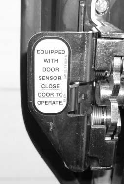
Cab Door Sensor
This machine may be equipped with a Cab Door Sensor.
Figure 10-30-6
The cab door has a sensor (Item 1) [Figure 10-30-6] installed which deactivates the lift and tilt valves when the door is open.


A decal is located on the latch mechanism (Item 2) [Figure 10-30-6]

The LIFT & TILT VALVE light (Item 3) [Figure 10-30-6] will be ON when the door is closed and the PRESS TO OPERATE LOADER button is pressed.
Special Applications Kit
Figure 10-30-7
Available for special applications to restrict material from entering cab openings. Kit includes 1/2 inch Lexan® front door, top and rear windows [Figure 10-30-7]
See your Bobcat dealer for availability.
Special Applications Kit Inspection And Maintenance
•Inspect for cracks or damage. Replace if required.
•Pre-rinse with water to remove gritty materials.
•Wash with a mild household detergent and warm water.
•Use a sponge or soft cloth. Rinse well with water and dry with a clean soft cloth or rubber squeegee.
•Do not use abrasive or highly alkaline cleaners.
•Do not operate windshield wipers on a dry surface.
•Do not clean with metal blades or scrapers.
AVOID SERIOUS INJURY OR DEATH
Adequately designed ramps of sufficient strength are needed to support the weight of the machine when loading onto a transport vehicle. Wood ramps can break and cause personal injury.

W-2058-0807
Be sure the transport and towing vehicles are of adequate size and capacity (See Performance on Page SPEC-10-2.), for weight of loader.
A loader with an empty bucket or no attachment must be loaded backward onto the transport vehicle [Figure 1040-1].
The rear of the trailer must be blocked or supported (Item 1) [Figure 10-40-1] when loading or unloading the loader to prevent the front end of the trailer from raising up.
Use the following procedure to fasten the Bobcat Loader to the transport vehicle to prevent the loader from moving during sudden stops or when going up or down slopes [Figure 10-40-2].

•Lower the bucket or attachment to the floor.
•Stop the engine.
•Engage the parking brake.
•Install chains at the front and rear loader tie down positions (Inset) [Figure 10-40-2]


•Fasten each end of the chain to the transport vehicle.

Because of the design of the loader, there is not a recommended towing procedure.
•The loader can be lifted onto a transport vehicle.
•The loader can be skidded a short distance to move for service (EXAMPLE: Move onto a transport vehicle.) without damage to the hydrostatic system. (The tires/tracks will not turn.) There might be slight wear to the tires/tracks when the loader is skidded.
The towing chain (or cable) must be rated at 1 & 1/2 times the weight of the loader. (See Performance on Page SPEC-10-2.)

Tools that will be needed to complete the following steps are:
MEL1563 - Remote Start Tool
MEL1565 - Service Tool Harness Control
MEL1566 - Service Tool Harness Communicator (Computer Interface)

The remote start tool (Item 1) [Figure 10-60-1] is required when the service technician is checking the hydraulic/hydrostatic system or adjusting the steering linkage.
The traction lock switch (Item 1) [Figure 10-60-2] is used to turn traction lock ON or OFF. Push the switch to the override postion. The switch will illuminate to indicate traction lock OVERRIDE, in this position the wheels are able to turn.
The maximum flow/variable flow switch (Item 2) [Figure 10-60-2] is used to activate the auxiliary hydraulics. Pressing the switch once will activate maximum flow. Pressing the switch again will activate variable flow. The switch will illuminate to indicate which flow rate is active. Pressing the switch a third time will turn the flow OFF. The switch is used when checking pressures and flow rate.
The auxiliary pressure release (Item 3) [Figure 10-60-2] is used to release hydraulic pressure to the front and/or rear auxiliary couplers. To release pressure; push and hold the switch for a few seconds.
NOTE:With the engine running; pushing and holding the pressure release switch will cause the engine to stop. To relieve the pressure; press the switch until the engine stops.
Suggest:
If the above button click is invalid.
Please download this document first, and then click the above link to download the complete manual.
Thank you so much for reading

Remote Start Tool - MEL1563 (Cont’d)
The 10-pin rectangular connector (Item 1) [Figure 10-603] is used to update software in the Deluxe Instrumentation Panel (Item 1) [Figure 10-60-4].
NOTE: The Service PC must be connected to the remote start tool to update the deluxe panel software.

The panel must be removed from inside the operator cab and plugged into this connector [Figure 10-60-3].


