
588 crawler and wheeled hydraulic excavators
7UNDERCARRIAGE
* * Refer to the Engine Service Manual
NOTA : La Société CASE se réserve le droit de modifier sans avis préalable les caractéristiques et la conception de la machine sans obligation d’y procéder sur la machine déjà vendue.
La description des modèles déclinés dans ce manuel a été établie à partir des caractéristiques techniques connues à la date de conception de ce document.
WARNING: This symbol means WARNING ! BE VIGILANT ! YOUR SAFETY IS AT RISK. The message that follows the symbol contains important safety information. Read it carefully. Be sure you understand the possible risks of injury or even death.
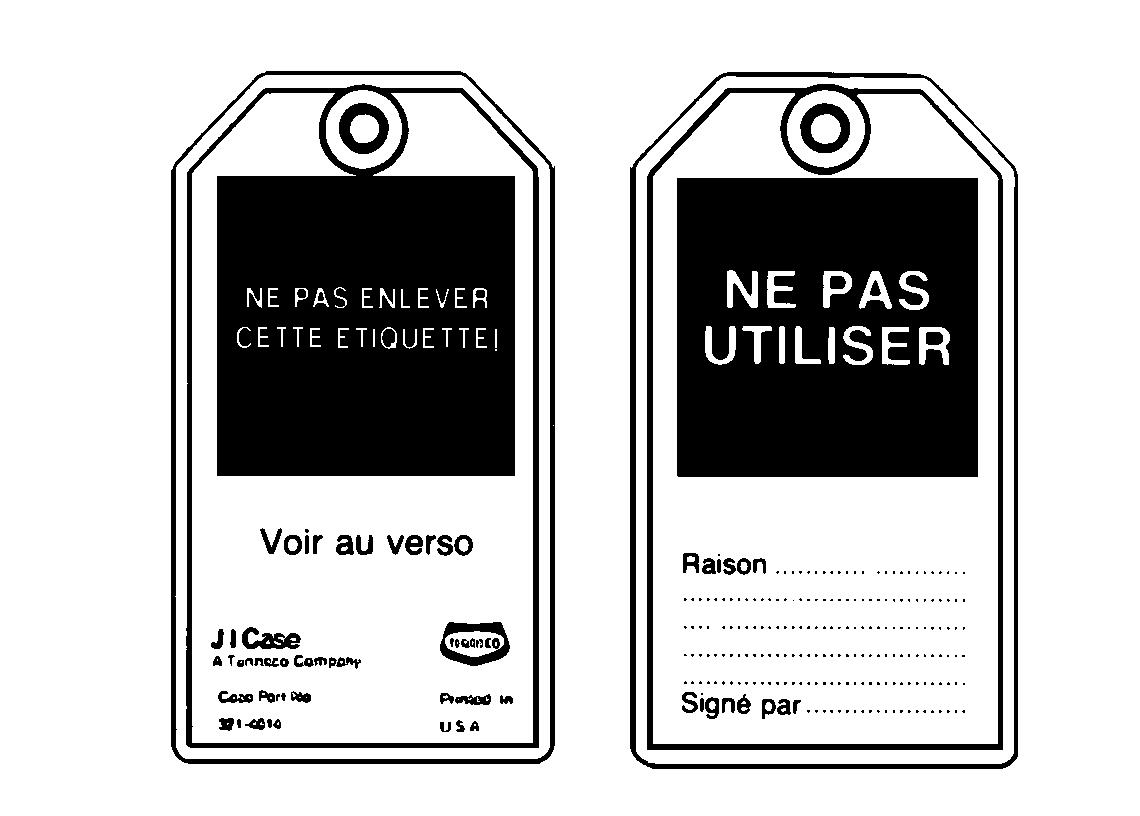
To avoid all risks, always follow the safety notes contained in this section and throughout this manual. Put the warning tag shown below on the key for the keyswitch when servicing or repairing the machine. One warning tag is supplied with each machine. Additional tags, Part Number 321-4614, are available from your service parts supplier.
WARNING : Prior to starting up the engine read the safety messages contained in the operator’s manual carefully. Read all safety stickers on the machine. Have people move back from the machine. Learn how to use the controls before starting up the machine. It is your responsibility to follow the manufacturer’s instructions on how to operate and maintain the machine. It is your responsibility to follow applicable rules and regulations. Service and Operator’s Manuals are available from your J.I. Case Dealer.
WARNING: If you wear loose clothing or if you omit to use safety equipment for your work, you risk injury. Always wear clothes that do not risk getting caught in the machine. Other safety equipment may be necessary, in particular : helmets, safety shoes, ear plugs, safety glasses, protection mask, thick gloves and reflecting clothes.
WARNING: When working close to the fan with the engine running, avoid wearing loose clothing and operate with extreme caution.
WARNING: Read the Operator’s Manual carefully and make sure you understand how to operate the controls correctly.
WARNING: Never operate the machine and attachment controls unless you are seated in the operator’s seat. If you are not in the operator’s seat, you run the risk of serious injury.
WARNING: The machine is built to carry the operator only. Do not allow passengers to ride on the machine.
WARNING: When checking the hydraulic circuits, follow procedures to the letter. DO NOT CHANGE procedures.
WARNING: Prior to operating the hydraulic cylinders of this machine for setting or to bleed the circuit, have all people standing around the machine move away.
WARNING: Wear gloves or insulated mittens when working on hot parts.
WARNING: Lower all attachments to the ground or rest them on stands before carrying out maintenance jobs.
WARNING: Fine sprays of hydraulic oil under pressure can penetrate the skin and cause serious infection. If hydraulic oil under pressure penetrates the skin, see a doctor immediately. Maintain all hoses and pipes in good condition. Make sure that all connections are properly tightened. Change all hoses or pipes that have been damaged or that are suspect. DO NOT CHECK for leaks with bare hands. Use a piece of cardboard or wood.
WARNING: To remove a hardened pin such as a pivot pin, or a hardened shaft, use a soft head hammer (brass or bronze) or a brass or bronze strip and a steel head hammer.
WARNING: When using a hammer to remove or reassemble pivot pins, or when using compressed air, or when using a grinder make sure to wear safety glasses that protect the eyes from all sides.
WARNING: Use proper lifting/hoisting equipment to lift wheels or tracks and always work on safe ground. Prevent the machine from moving using correct safety chocks.
WARNING: When performing maintenance or repair operations on the machine, make sure that the work shop floor, the cab and the steps of the excavator are free from oil, water, grease, tools etc. Use oil absorbing material or rags as necessary. Always think safety.
WARNING: Certain components of this machine are very heavy. Use hoisting tools or additionnal assistance as recommended in this manual.
WARNING: Exhaust fumes can cause death. If it is necessary to start up the engine in a closed building, evacuate exhaust fumes using an exhaust pipe extension. Open the doors and let fresh air into the building.
WARNING: When battery liquid is frozen, the battery can explode if : (1) you try to charge the battery or (2) you try to start the engine by connecting an auxiliary power source. To prevent battery electrolyte from freezing keep the battery fully charged. If you do not follow these instructions, you or others nearby may be injured.
WARNING: Batteries contain acid and explosive gases. A spark, a flame or an improper cable connection may cause an explosion. For proper connection of cables to the battery of this machine see the Operator’s Manual. If you do not follow these instructions, you risk severe injury.
TWIN WHEELS
Safety rulesSafety instructions
WARNING: In all cases, before removing twin wheels, always deflate both tyres completely.
WARNING: If a tyre bursts it can cause serious injury. Check tyres regularly to see that they are in good condition and always be sure to inflate them to the correct pressure.
WARNING: Never face a tyre when checking pressure or adding air. Always stand in front of the tread. Use an inflation cage if the wheel has been removed from the machine. Make sure all people standing in the area move well away.
WARNING: Never weld near a tyre.If this can not be avoided, it is mandatory to remove the tyre before performing any welding operations.
WARNING: Make sure that all decals on the machineareperfectlylegible,cleanthemregularly and replace any decals which are damaged, missing or painted over, with new ones.
• Use appropriate, good quality tools to disassemble the various wheel components. Never use a hammer. Use a rubber, plastic or copper-faced mallet.
IMPORTANT: Never remove the inner tyre valve extension, as this will be necessary afterwards for inflating and deflating the tyre.
IMPORTANT: If the valve or the valve extension are no longer accessible, take the necessary precautions and then, imperatively, puncture the tyre.
• Use suitable grease to facilitate the installation and removal of the tyre.
• Never re-inflate a tyre on the machine which has been used at a pressure lower than 5.6 bar.
• Check the various components: tyre, rim, shoulder, retaining ring and replace any defective items.
• Never reuse a retaining ring which is distorted or rusty.
CLEANING
GENERAL INFORMATION
Clean all metal parts except bearings with white spirit or steam. Do not use caustic soda when steam cleaning. After cleaning, dry and lubricate all parts. Clean hydraulic lines with compressed air. Clean bearings with kerosene, then dry them and lubricate them.
INSPECTION
Check all parts when disassembled. Change all parts showing wear or damage. Scratches that are not too deep can be removed by honing or with a rag dipped into buffing compound. A full visual inspection to detect wear and pitting and subsequent changing of parts will prevent premature failure.
BEARINGS
Check that bearings rotate freely. If their adjustment is too loose or if they do not run regularly, change them. Wash bearings with a good solvent or kerosene and let them dry. DO NOT DRY BEARINGS WITH COMPRESSED AIR.
NEEDLE BEARINGS
Before inserting needle bearings into a bore, remove all metal particles from the edge of the bore. Prior to mounting bearings with a press, coat the inside and the outside of the bearing with vaseline.
GEARS
Check all the gears for wear or damage. Change worn or damaged gears.
SEAL RINGS, O-RINGS, GASKETS
Always use new seal rings. O-rings and gaskets. Coat sealing rings and O-rings with vaseline.
SHAFTS
Check all shafts showing signs of wear or damage. Check that the surface of a shaft running in a bearing is not damaged.
SPARE PARTS
Always use original CASE spare parts. To order spare parts, see the Spare Parts Catalogue to indicate the proper reference of original CASE spare parts. Failures caused by the use of parts that are not original CASE spare parts are not covered by the warranty.
LUBRICATION
Use only oils and lubricants specified in the Operator’s and Service Manuals. Failures due to the use of oils and lubricants not specified are not covered by the warranty.
Before performing any service work on a machine, the following steps must be carried out in the order shown :
- Park the machine on hard, flat ground.
- Lower the attachment to the ground.
- Stop the engine and let it cool down.
- Turn the battery master switch to the “OFF” position and remove the key.
ATTENTION : When the machine is operating, the components of the engine and the hydraulic pump attain a high temperature. To avoid being burnt by hot metal or scalded by high temperature water or oil, let the machine cool down before beginning any service operation.
Removal and Installation
STEP 6
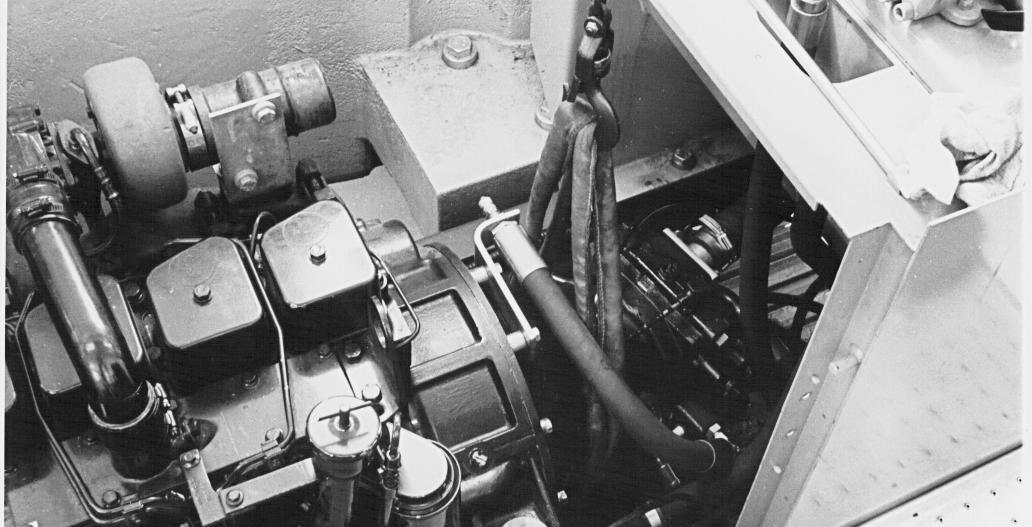
Remove the exhaust silencer and its bracket.
STEP 7
Remove the hose connecting the turbocharger to the air filter.
STEP 8
Disconnect the negative cable (1) first and then the other cables.
STEP 2
Remove the access panels located under the engine.

STEP 3
Remove the exhaust silencer outlet tube.
NOTE : When installing, make sure that the exhaust outlet is pointing towards the rear.
STEP 4
Remove the upper hood using a suitable lifting device.
STEP 5
Remove the side panel on the walkway side.
1 ENGINE OIL PRESSURE PRESSOSTAT.
PDG0416
2 ENGINE COOLANT SOLUTION TEMPERATURE SENDER.
3 ENGINE SHUT-DOWN SOLENOID VALVE
4 ALTERNATOR (SEE SECTION 4003) FOR WIRING IDENTIFICATION.
5 STARTER MOTOR (SEE SECTION 4004) FOR WIRING IDENTIFICATION.
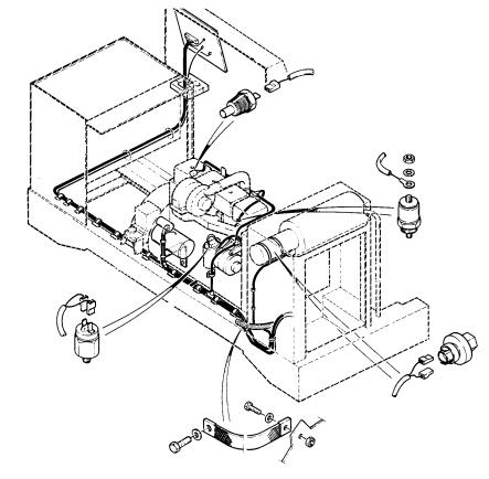
6 EARTHING STRAP.
7 AIR FILTER RESTRICTION PRESSURE SWITCH.
STEP 11
Remove the expansion reservoir cap.
NOTE : Do not remove the cap when the engine is hot. The system is still under pressure and you risk being scalded.
STEP 10
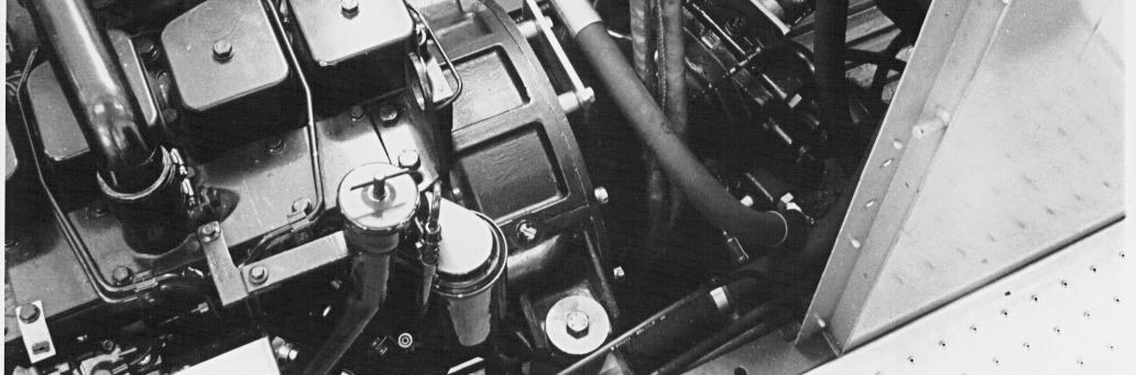
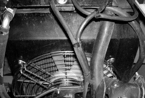
Remove the lower tray under the operator’s compartment. Place a receptacle of about 30 litres underneath and then disconnect the hose (1) from the heating system and allow the coolant solution to flow out.
STEP 12
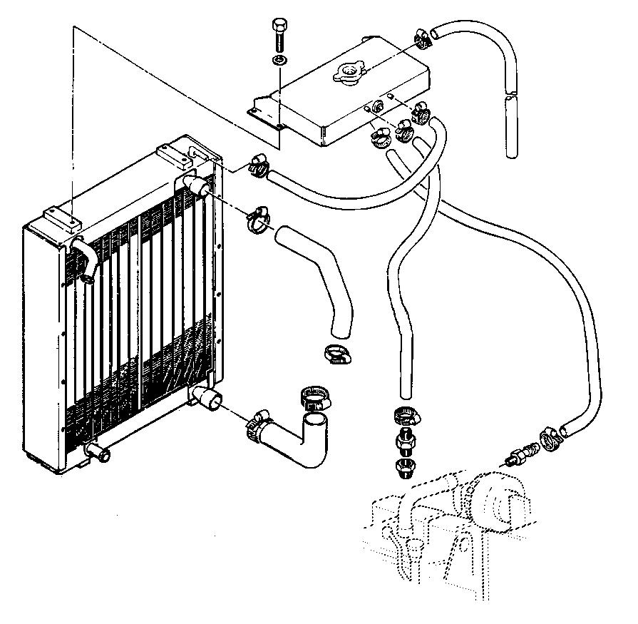
Disconnect, label and remove the cooling system hoses from the engine in numerical order.

NOTE : When installing, make sure that the system hoses are clean.
1OVERFLOW HOSE
2 ENGINE DEGASSING HOSE
3 RADIATOR DEGASSING HOSE
4 ENGINE/RADIATOR RETURN HOSE
5
STEP 13
STEP 15
STEP 14
STEP 17
STEP 19
Remove and plug the hydraulic fluid return hose to gain access to the shroud retainers.
NOTE : Refer to “Tools required” on page 2 for plugging the hydraulic fluid return hose.
STEP 18
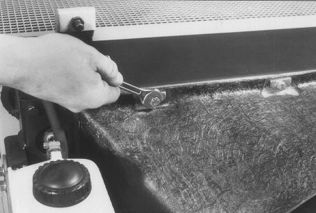
Remove the shroud fastening hardware and move the shroud towards the engine to gain access to the fan retaining screws.
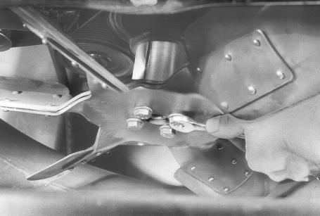
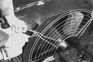
Remove the four fan retaining screws and remove the fan and spacer. Remove the fan shroud.
NOTE : When installing, the fan shroud should be installed resting on the engine. Install the spacer and the fan and then tighten the screws to a torque of 44 Nm.
STEP 20
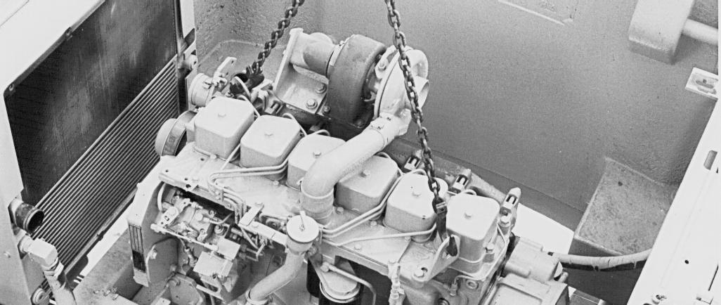
Attach a suitable lifting device to the engine lifting eyes. Weight of engine:350 kg
STEP 21
STEP 23
Using a suitable sling, support the hydraulic pump so as to prevent it dropping during removal of the engine.
STEP 22
Remove the hydraulic pump fastening hardware.
NOTE : When installing, tighten the hydraulic pump retaining screws to a torque of 44 Nm.
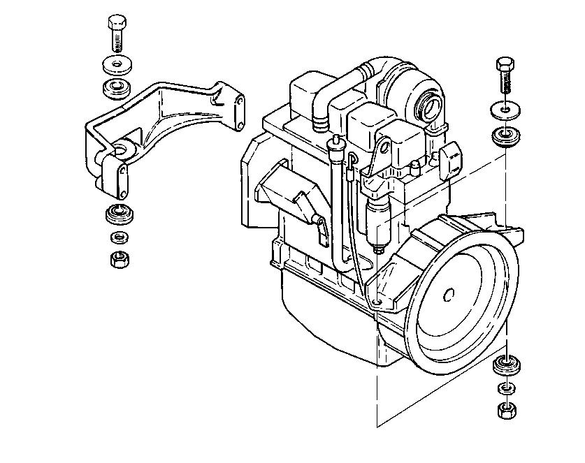
NOTE : When installing, the pressure control hose and its bracket must be installed.
Remove the nuts (1), the washers (2) and remove the screws (3) and the thrust washers (4).
When installing, make a visual check of the condition of the rubber spacers (5). Replace them with new spacers if necessary. Tighten the engine support retaining screws to a torque of 217 to 271 Nm.
Carefully lift the engine. Move it towards the radiator until it is disengaged from the pump coupling. When there is nothing to prevent the removal of the engine, install it on a suitable repair bench.
STEP 25
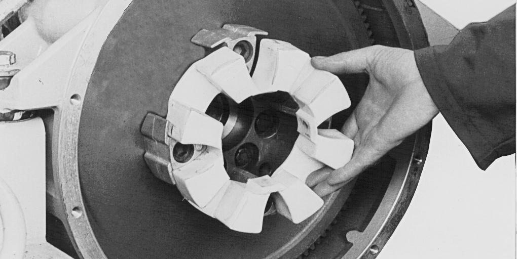
Remove the flexible coupling (1), check wear and condition of the coupling visually and replace it by a new one if necessary.
Remove the screws (1) and remove the centering lugs (2). Make a visual check of the wear and general condition of the centering lugs and replace them if necessary.
NOTE :
PDG0419
(A)INCORRECT
(B)CORRECT
When installing, apply Loctite 638 on the screws, position the centering lugs correctly, and tighten the screws to a torque of 220 Nm.
NOTE : If it is necessary due to wear to replace the flexible coupling and the centering lugs, the splined sleeve should also be replaced.
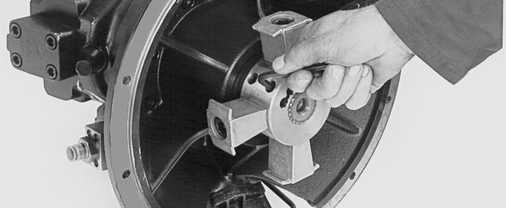

Remove the splined sleeve (1) from the hydraulic pump. Replace it if necessary.
NOTE : When installing the splined sleeve (1), install the splined sleeve on the pump shaft. The splined sleeve should be pushed fully home against the pump shaft shoulder. Tighten the retaining screws (2) to a torque of 100 Nm.
NOTE : When installing the engine, proceed in the reverse order to that used for the removal.
Before using the machine, perform all the following operations :
-Fill the cooling system (see Operator’s Manual).
-Turn the battery master switch to the "ON" position.
-Bleed and prime the fuel circuit (see Operator’s Manual).
-Check that the engine oil pressure warning lamp goes out when the engine is running.
-Bleed the cooling system (see Operator’s Manual).
-Check the hydraulic system, fuel system and cooling system for leaks.
-Stop the engine and check all levels. Top up if necessary.
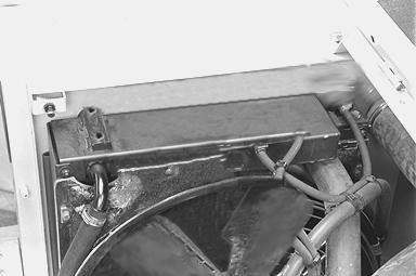
RADIATOR AND OIL COOLER
Before performing any service work on the machine, the following steps must be carried out in the order shown:
- Park the machine on hard, flat ground.
- Lower the attachment to the ground.
- Stop the engine.
- Turn the battery master switch to the “OFF” position and remove the key.
- Simultaneously operate the emergency foot pump and the control lever so as to release the pressure in the hydraulic system.
- Unscrew the hydraulic reservoir pressure release cap two turns. Retighten the cap.
WARNING: When the machine is operating, the components of the engine and the hydraulic pump attain a high temperature. To avoid being burnt by hot metal or scalded by high temperature water or oil, let the machine cool down before beginning any service operation.
Removal and Installation
STEP 1
Remove the lower tray from under the operator’s compartment and the access panels from under the upperstructure. Remove the engine side hood.
STEP 2
Remove the expansion reservoir cap.
IMPORTANT: Do not remove the cap when the engine is hot. the system is still under pressure and you risk being scalded.
STEP 3
Place the heating control lever in open position.
STEP 4
Disconnect the return hose from the heater unit and allow the coolant solution to flow into a suitable receptacle. Reconnect the hose once the circuit has been completely drained.
STEP 5
Close the shut-off valve under the hydraulic reservoir. IMPORTANT: After an operation which has required the shut-off valve to be closed, never start the engine before making sure that the shut-off valve has been reopened.
STEP 6
STEP 7
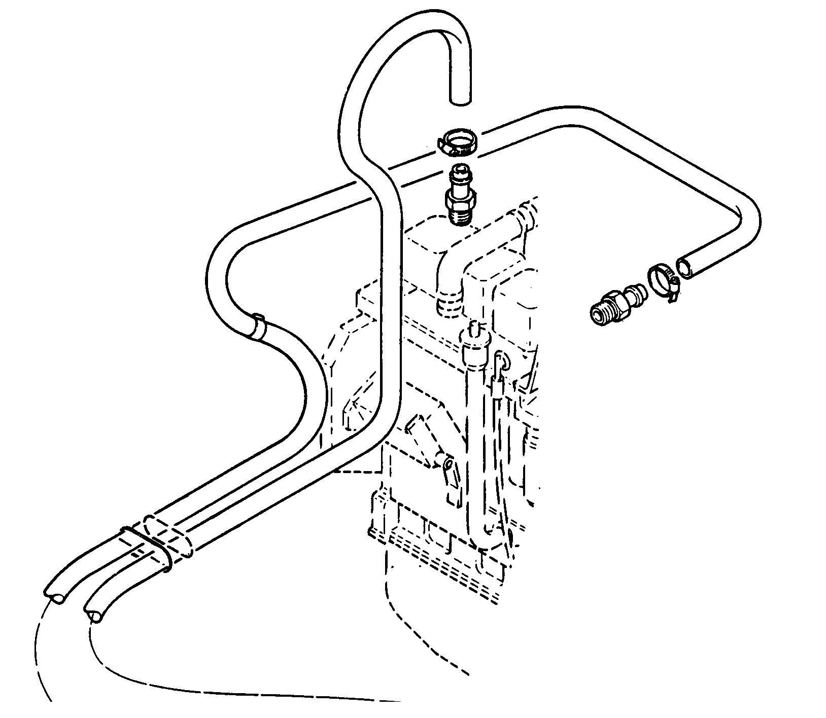
Remove and plug the upper hydraulic fluid hose (1). To avoid losing fluid, disconnect the oil cooler (4) return hose (3) from the hydraulic reservoir (2) and drain the oil into a clean receptacle. Reconnect the return hose (3) to the reservoir (2) then remove and plug the oil cooler (4) hose (5).
NOTE: Refer to “Tools required” on page 3 for plugging the hoses (1) and (5).
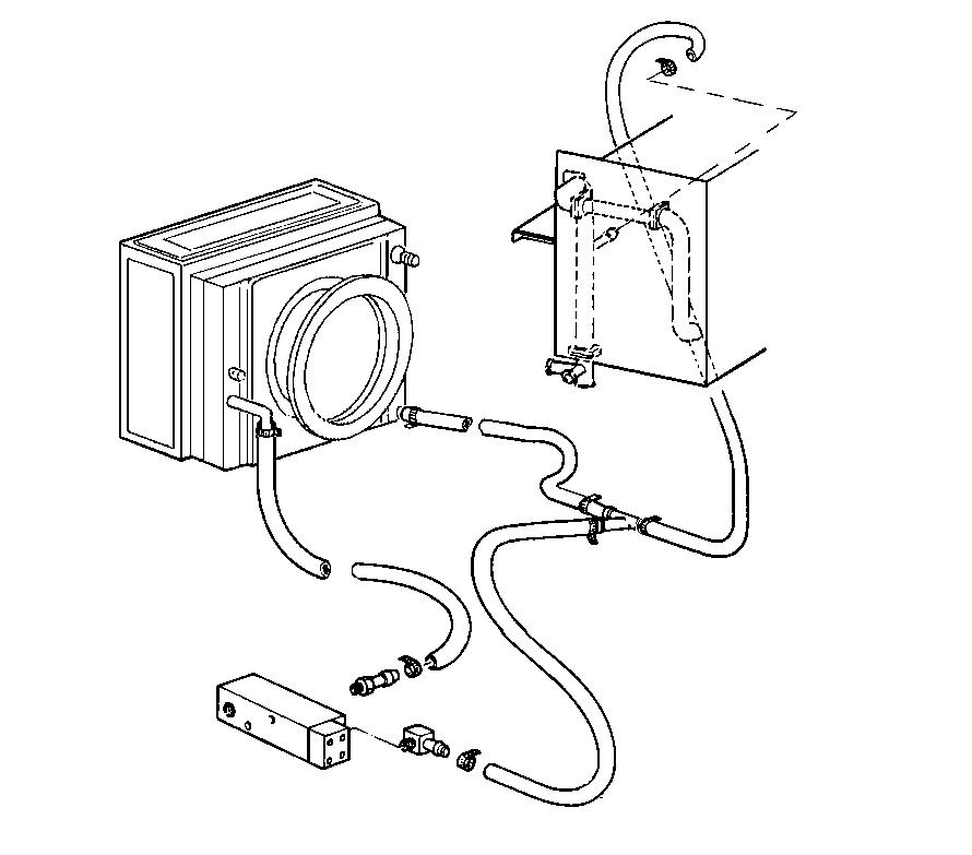
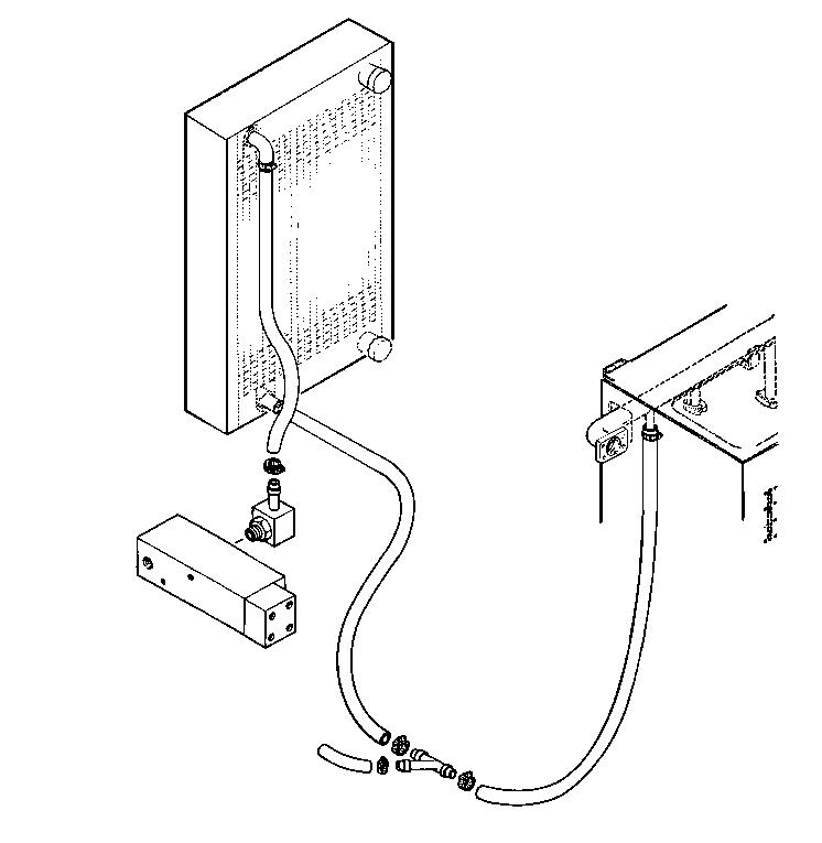
Remove the degassing hose (6) from the radiator and plug it.
Remove and plug the water pump/radiator return hose (7).
Remove and plug the water pump/radiator feed hose (8).
Remove the mounting screws (9) and washers (10) from the coolant reservoir (11).
STEP
STEP 9
STEP 11
Remove the shroud fastening hardware and move the shroud towards the engine to gain access to the fan retaining screws.
STEP 10
Remove the four fan retaining screws and remove the fan and spacer. Remove the fan shroud.
NOTE: When installing, the fan shroud should be installed resting on the engine. Install the spacer and the fan and then tighten the screwsto atorque of44Nm.
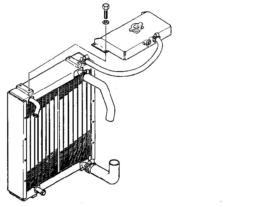
Remove the lower retainers (1) and (6) and the upper retainers (5) from the radiator (3). Remove the lower (4) and upper (5) flexible mountings.
NOTE: It is not possible to remove the lower retainers (6) unless the counterweight has already been removed.
Remove the lower fastening hardware (1) and the upper fastening hardware (2) from the radiator (3). Remove the lower (4) and upper (5) flexible mountings.
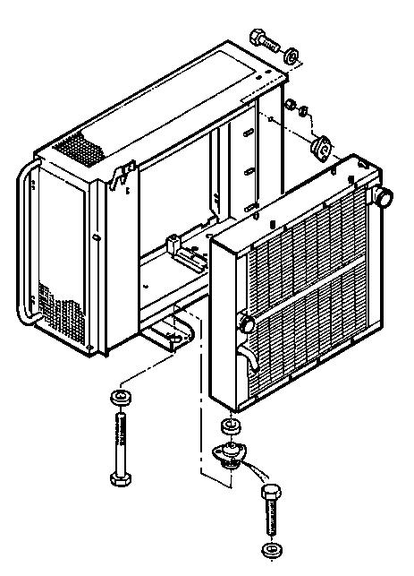
NOTE: When installing, visually check the wear and general condition of the rubber mountings (4) and (5). Replace them if necessary.
NOTE: Installation is carried out in the reserve order from that of removal.
Before using the machine, all the following operations must be performed:
- Check the oil level in the hydraulic reservoir. Top up if necessary.
- Turn the battery master switch key to the “ON” position.
- Fill the cooling system (see procedure on page 10).

- Bleed the cooling system (see procedure on page 10).
- Check the hydraulic cooling system for leaks.
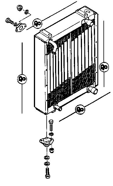
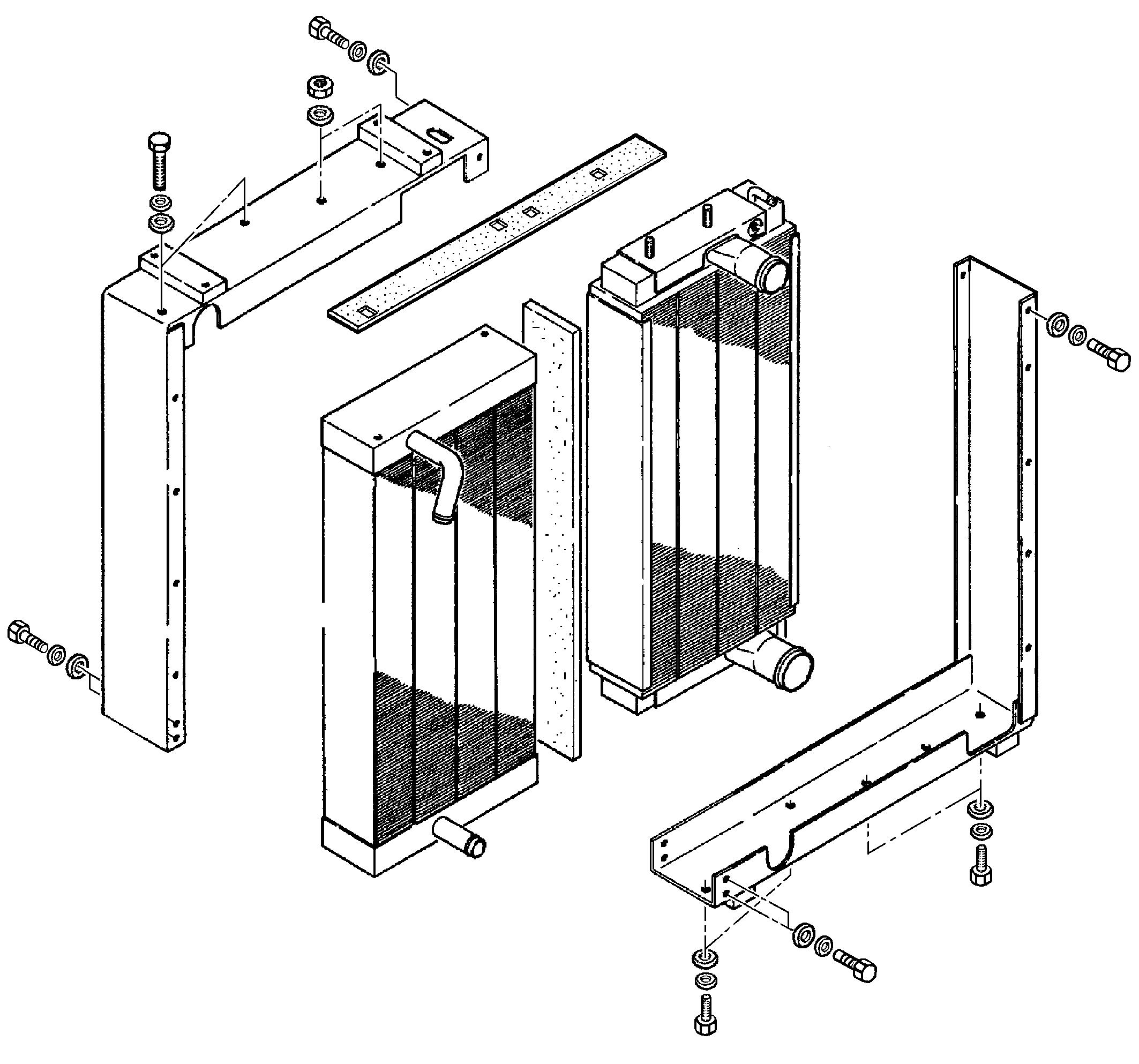
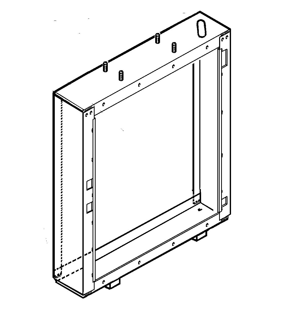
REPLACING THE RADIATOR OR THE OIL COOLER
Model 588, 788 (bolted radiator and oil cooler frame)
Disassembly and assembly
NOTE: The parts are numbered in order of disassembly. Assembly is carried out in the reverse order from that of disassembly.
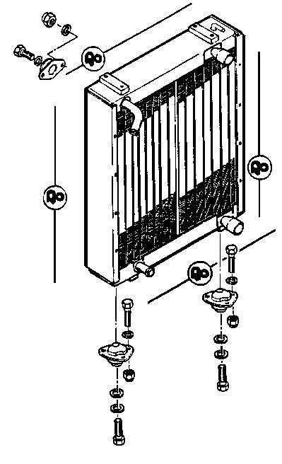
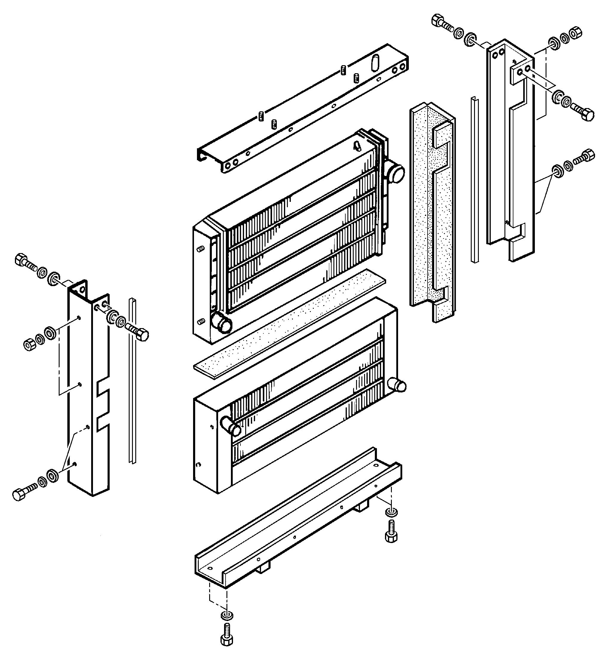
Model 988 (welded and bolted radiator and oil cooler frame)
NOTE: Grind the welds shown by an asterisk.
NOTE: When reassembling, flatten off the welds and scratch off the paint at the weld locations.
Disassembly and assembly
NOTE: The parts are numbered in order of disassembly. Assembly is carried out in the reverse order from that of disassembly.
Suggest:
If the above button click is invalid.
Please download this document first, and then click the above link to download the complete manual.
Thank you so much for reading

Filling the cooling system
STEP 1
Fill with coolant solution via the expansion reservoir until it overflows.
IMPORTANT: Use suitable coolant solution (see “Specifications”, page 3.
STEP 2
Unscrew the heating unit bleed screw, let the air escape until coolant solution flows out then retighten the screw.
STEP 3
Run the engine for a few minutes then check the level in the expansion reservoir again and top up if necessary.
STEP 4
Install the expansion reservoir cap.
WARNING: Do not run the engine in an enclosed space. If necessary, make sure there is good ventilation under all circumstances.