
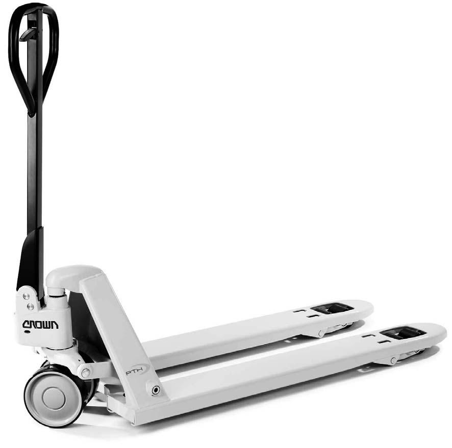
SERVICE + PARTS MANUAL PTH50 SERIES

From Serial No. SZ_______ on
Orderno.: 812570-006
TABLE OF CONTENTS
Notes:
Notes:
Introduction
This manual is intended for the service technician. It includes information about maintenance, troubleshooting and a list of replacement parts for the hand pallet truck PTH50.
Replacement Parts
When ordering replacement parts from this manual, always specify:
–the part number
–the model number of the truck
–the serial number of the truck
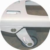
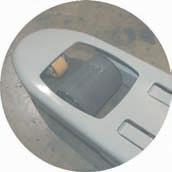
The data plate with model and serial number is located on the rear of the fork carriage (see Fig.15292).
Model Number
This number is used as a brief description of the truck. Refer to the example below for the method used to determine the model number and its meaning.
12
PTH50-27-48
3 4
1Image Generator (PTH = Hand Pallet Truck)
2Fork Spread (in inches)
3Fork Length (in inches)
4Capacity* [50 = 2300kg (5000lbs)]
*Actual rated capacity may vary, depending on special equipment or modifications. Refer to the data plate for actual cpacity rating.
Lubrication
The truck is designed to require minimum lubrication. Self-lubricating bushings and sealed bearings are used throughout the truck with two exceptions:
–A single grease nipple is provided so the bearing in the traverse can occasionally be lubricated (use part number 063002-034).
–The handle lever ball detent needs occasional lubrication (use part number 363108-001).
15292
Lubrication and Inspection
15310
I-1Handle, Actuating LeverInspect handle; lubricate handle detent ball area.
I-2Entry Roller, Load Rollers Check for cuts.
I-3RisersKeep risers lubricated. Check for signs of damage or wear.
I-4ForksInspect forks for cracks on exterior surface.
I-5Grease NippleEnsure bearing is properly lubricated; use part number 063002-034.
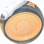
I-6Steered WheelsInspect wheels for cuts.
I-7Hydraulic UnitMake sure pump is clean. Inspect for any signs of damage or wear.
I-8SpringCheck spring for wear, damage, and cleanliness.
Hydraulic Unit
Functions
(Refer to Figures 15295 & 15305EU)
Raise
Raise function is selected by pushing actuating lever down to raise position (4, Fig.15305EU).
When the handle is raised, the pump piston is actuated upward by means of spring (5, Fig.15295) and draws fluid from reservoir through control chamber, around the upper check ball (24) in the cartridge valve, through chamber (25) and into the pump cylinder. Fluid movement continues in this direction until the top of the handle stroke is reached.
Pushing the handle downward forces fluid out of the pump cylinder and through the chamber. The upper check ball (24) in the cartridge valve blocks the control piston chamber and reservoir. This causes the fluid to continue past the lower check ball (23) in the cartridge valve and into lift chamber, moving the lift piston ram upward. The forks are raised.
When the end of the handle stroke is reached, the handle is raised again and the cycle repeats.
As the handle is raised, the lower check ball in the cartridge valve(23) closes, thus retaining fluid in the lift chamber.
Neutral
Neutral function is selected by engaging actuating lever in neutral position (3, Fig.15305EU). In this position tension is applied to the pull rod and chain. The chain pulls the connector and rotates the cam shaft moving the control piston downwards.
The downward movement of the control piston unseats the upper check ball(24) in the cartridge valve in the control piston chamber.
Raising the handle draws fluid from reservoir through control piston chamber around the upper check ball(24) in the cartridge valve through the control piston chamber and into the pump cylinder.
When the handle is pushed downwards, since the upper check ball in the cartridge valve (24) is held unseated, fluid returns to reservoir, by the same route.
Lower
Pulling the actuating lever up to lower position (2, Fig.15305EU) lowers the forks. This transmits the downward movement of upper check ball (24) in the cartridge valve to the tappet and unseats the lower check ball (23) in the cartridge valve opening a passageway and allowing fluid to escape from the lift chamber, back into the reservoir, thus lowering the lift piston ram and the forks.
As the actuating lever is released, springs (5 & 22, Fig.15305EU) and the spring in the handle return all components to their previous positions.
Fluid Level
With the forks lowered, check hydraulic fluid by unscrewing the filler plug. Insert a clean probe.
• Maximum fluid level should be 38mm (1.5in) from top of pump cover.
• Minimum level 57mm (2.25in) from top of pump cover.
Hydraulic Unit
Capacity of the hydraulic unit is:
• 46mL (15.4USfloz) minimum
• 58mL (19.7USfloz) maximum
cles attracted to the magnet can be cleaned off. The hydraulic unit must be partially removed to remove the ram.
Hydraulic Unit Removal
(Refer to page 12)
1.Raise forks completely and securely block rear of truck approximately 100mm (4.0in).
2.Remove roll pin from frame.
3.Drive out roll pin. Remove hub caps & retaining rings. Remove wheels from axle. Remove retaining ring - not necessary for removal of ram to clean magnet.
4.Pull actuating lever to lower position, while pressing lift piston ram into cylinder. The hydraulic unit can now be lifted out.
Type of Fluid
When operating in temperatures above freezing, use Crown anti-wear hydraulic fluid, part number 363504-101, or equal. For units being operated in temperatures below freezing, use Crown low temperature hydraulic fluid, part number 363505-101, or equal. Do not use brake fluid.
To obtain maximum life from the hydraulic unit, a magnet is located at the base of the ram to attract and hold any metal particles that could cause damage to seals, valve seats and other parts. Approximately every three months, the ram should be removed so that any parti-
Thank you very much for your reading. Please Click Here. Then Get COMPLETE MANUAL.NOWAITING

NOTE:
If there is no response to click on the link above, please download the PDF document first and then clickonit.
Hydraulic Unit
Key to Figure 15295
Hydraulic Unit Disassembly
(Refer to Figure 15295)
Lift Piston Ram
Remove by pulling through the top of unit out of cylinder. Seal (13) is then removed followed by circlip (14) which allows removal of the bushing, seal (17) and spacer. Once the ram is removed, the magnet (19) should be cleaned.
Pump Piston
Circlip (8) is removed allowing pump cylinder to be removed with O-rings (21), back-up ring, spring (22), pump piston, washer and retaining ring (14). Seals (13) and (17) may be removed at this time.
If pump piston and cylinder cannot be easily removed (due to seals "sticking"), use gentle downward pressure on the handle to push them out. Be careful not to compress the spring too much since this may cause the entire assembly to be released in a hazardous manner.
Cartridge Valve
The cartridge valve controls the lift/lower functions. Internally it has an upper and lower check ball and spring that controls the flow of hydraulic fluid. Inspect seals on cartridge valve, if needed, replace all seals on cartridge valve. Disassemble cap screw from chain connector and remove chain, link and connector through hole in handle pin. Drive out roll pin and remove handle pin.
The entire handle assembly can now be removed. Rotate cam shaft so roll pin is parallel to control piston. Drive out roll pin from cam shaft. Remove control piston spring and O-ring. Finally, remove cam shaft.