Repair manual
Original repair manual
ARION 460-410

This repair manual applies to the following tractors:
Description
Type
Tractor serial number From to
ARION 460-430 A52 A5300000 —
ARION 420-410 A5200000 —

Number Value
1 580 kg Complete engine
Note – Description
For unspecified tightening torques, refer to the section entitled: "Tightening torques".
Lifting heavy components.
Risk of death or serious injury.
► Use certified slings or chains in perfect working order.
► Use a certified hoist in perfect working order.
► Use a certified jack or stand which can support the load.
► Use the jack or stand on a flat, horizontal, sufficiently firm surface.
► Place the jack or stand in a suitable location.
Lubricants and fuels end up in the environment.
Environmental pollution
► Collect and store lubricants and fuels in suitable containers and dispose of them properly.
Special tool – Reference no. Carriage to be uncoupled No. 00 1148 105 0


Special tool – Reference no. Extension No. 00 1148 106 0

1
Engine lifting brackets kit
No. 00 1152 870 0
Component parts of the NEF 4 kit
2
Special tool – Reference no.
Bracket at the front of the engine No. 1149 878 1/3
3 Bracket at the right-hand side of the engine No. 1149 878 1/2D
4 Bracket at the left-hand side of the engine No. 1149 878 1/2G

► Disconnect the battery. ► Remove the two front wheels. ► Remove the two front wings (optional).
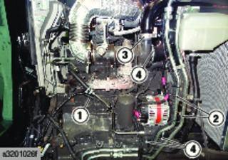
► Remove the engine bonnet (1). Engine bonnet
► Remove the left-hand side cover (2). ► Drain the engine. ► Drain the A/C circuit. Air conditioning – General informationFunction:12 Cab – Driving position
► Drain the cooling circuit.

► Drain the pneumatic brake circuit (optional).
► Drain the braking circuit.
► Decompress the suspended front axle circuit (optional).
► Remove the rear left-hand wheel.
► Remove the protective panels (1) and (2).
► Remove the main tank. Main tank
► Disconnect the unions (1).
► Remove the pressure controller from the trailer air brake (2) and its support.


► If fitted, remove the bracket and side member (1) from the loader frame on the left-hand side using a suitable lifting tool.

The left-hand bracket and left-hand side member assembly weighs 140 kg.
► Remove the exhaust booster (1).


► Remove the protective panels (2), (3) and (4).
► Remove the bolts (1) and the panel (2).
► Undo and remove the bolts (1).
► Remove the panel (2).
► Disconnect the connector (1) from the NOx output module.
► Undo and remove the bolts (2).


► Move the NOx output module (3) towards the “SCR” and “CUC” catalytic converters.

► Disconnect the connectors (1).

► Undo and remove the nuts (2) from the exhaust tube.
► Discard the seal (3).
► Disconnect and plug the connectors (1).
► Remove the hoses from the "SCR" catalytic converter support.

► Sling and remove the "SCR" catalytic converter assembly and its support and the booster foot using a suitable lifting tool.
The assembly weighs 75 kg. Handle the assembly with care to avoid damaging the catalytic converter.

► If fitted, disconnect and detach the connector (1) used to control the front loader.


► If fitted, remove the bolt (1) mounting the pipe support to the front loader.

► If equipped with a front loader:
► – Close the accumulator valve (1).
► – Disconnect and plug the connector (2).

► – Remove the bolts (3) and place the "MACH SYSTEM" on the ground, leaving the hydraulic pipes connected.

► If fitted, remove the bracket, side member and cross member (1) from the loader frame on the right-hand side using a suitable lifting tool.
The right-hand bracket, right-hand side member and cross member assembly weighs 155 kg.
AdBlue ® is slightly corrosive.
Risk of injury.
► Avoid contact with AdBlue ®
► Wear gloves and protective goggles when handling AdBlue ®
► In case of contact with the eyes or skin, rinse thoroughly in fresh water without rubbing .
► Disconnect the connector (1).
► Disconnect the urea injector supply pipe (2).
► Disconnect the coolant hoses (3).

► Remove the clamp (4).
► Remove the exhaust tube (5).
► Remove the protective panel from the electric starting motor.

► Disconnect the electric wiring harnesses from the electric starting motor (1).
► Remove the mounting bolts from the electric starting motor (2).

► Remove the electric starting motor (3).

► Remove the protective grilles (1).
► Loosen the clamp (2) and disconnect the hose.
► Unscrew the fan (3).
Note the direction of loosening of the nut, as this nut has a left-handed thread.
► Remove the mounting bolts from the radiator nozzle (4).


► Detach the coolant tank overflow pipe (5).
► Remove the bolts (6) and remove the tube and the hose (7) from the nozzle.
► Simultaneously remove the fan (3) and the nozzle (4) from the right-hand side of the engine.
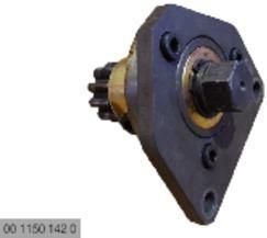
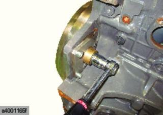
► Remove the bolts (1) of the front power take-off drive flange (optional).
Turn the engine with the special flywheel rotating tool to access the bolts.
► Move aside the front power take-off shaft (2).
► Remove the turbocharger protective panel (1).

► Remove the clamp (2).
► Loosen the clamp (3) and disconnect the hose.
► Disconnect the connector (4).
► Disconnect the coolant heater (1).
► Remove the pipes (2).
► Remove the clamp (3).
► Loosen the clamps (4) and disconnect the hoses.

► Remove the pipes (1).
► Remove the support (1) from the hoses and wiring harness on the front chassis.


► Open all of the radiators.
► Remove the panels (1) and (2).
► Disconnect the connectors (1).
► Disconnect the connector (2).
► Detach and remove the electric wiring harness (3) from the front chassis and from the engine.


