
Shop Manual
023-00040E
Serial Number 1001 and Up
February 2001
Daewoo reserves the right to improve our products in a continuing process to provide the best possible product to the market place. These improvements can be implemented at any time with no obligation to change materials on previously sold products. It is recommended that consumers periodically contact their distributors for recent documentation on purchased equipment.
This documentation may include attachments and optional equipment that is not available in your machine’s package. Please call your distributor for additional items that you may require.
Illustrations used throughout this manual are used only as a representation of the actual piece of equipment, and may vary from the actual item.
023-00040E Shop Manual
TRANSMISSION DISASSEMBLY

1.Fasten transmission on an appropriate support stand.
2.Disassemble complete shift control, remove pressure lines and duct plate.
CONVERTER-INPUT
1.Separate torque converter from transmission, using lifting device.


S0607070K
Transmission and Torque Converter (ZF)
2.Loosen screw connection.
3.Separate bearing cover from converter


7.Remove shim.
8.Remove rectangular ring (Figure 79).

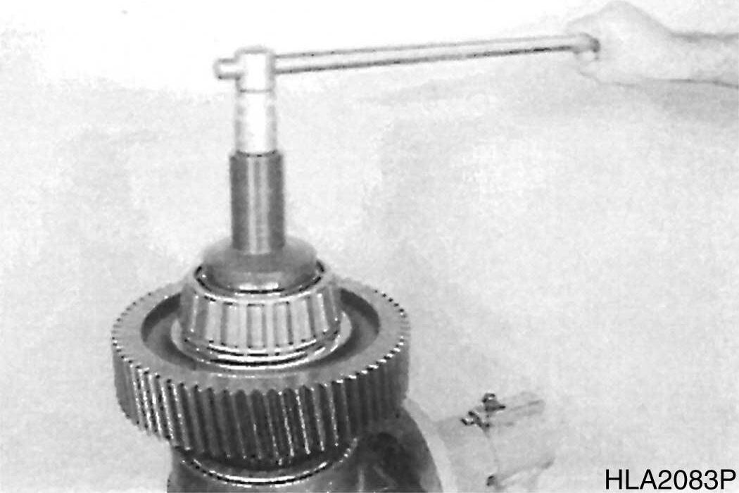
9.Press drive shaft out of spur gear bearing. Remove released inner bearing race and spur gear.


10.If necessary, drive outer bearing race out of housing bores.
11.Press

12.Remove converter pressure valve.
DRIVE SHAFT PUMP POWER TAKE-OFF
1.Pull complete drive shaft out of gearbox housing (pump).
2.Remove rectangular ring (Figure 84).
3.Separate spur gear from shaft and remove snap ring (Figure 85).


Transmission and Torque Converter (ZF)
S0607070K

4.Pull inner bearing race from spur gear.

5.Loosen socket head screw and remove it along with clamping plate.

6.Pull inner bearing race and drive from shaft.

NOTE: Support puller on end face/ drive shaft. Pay attention to released shims.
7.Separate inner bearing race from driver.

NOTE: Pay attention to released shim.
8.Remove snap rings (3x).
TRANSMISSION PUMP
1.Tilt gearbox housing 180°

2.Loosen hex. head screws and remove both pump flanges.
3.Loosen socket head screws (M8) and position Puller device (s).
4.Pull transmission pump out of housing bore.
NOTE: Tapping housing face is a help during extraction operation.
OUTPUT- LAYSHAFT ASSEMBLY


1.Loosen screw connection and remove brake caliper.
2.Unlock and loosen hex. head screws, tap brake disk loose and separate it from output shaft.

Transmission and Torque Converter (ZF)
S0607070K
3.Pry
5.Remove


8.Tilt gearbox housing 180°


9.Loosen hex. head screws and pull bearing cover -K1/KV out of housing bore.
10.Loosen hex. head screws and remove bearing cover KR/K2 and K3/K4.
11.Remove rectangular rings (3 pieces/axle), see Figure 100.

12.Remove snap ring and remove released washers.

Transmission and Torque Converter (ZF)
S0607070K
13.Support output flange against gearbox housing, see Figure 102.


14.Loosen hex. head screws and separate housing cover from gearbox housing, using forcing screws and lifting device.
15.Unlock and loosen hex. head screws.
16.Remove output flange and pry shaft seal out of housing.

18.Remove output gear along with shaft.
19.Separate output shaft from spur gear.


20.Pull inner bearing race from output gear.

21.Remove plate.
Transmission and Torque Converter (ZF)
S0607070K
22.Drive roller bearing out of housing bore and remove it.

DISASSEMBLE CLUTCHES AND LAYSHAFT GEAR

1.Remove clutches - K3/K4, KR/K2 and KV/ K1- by means of lifting device.

NOTE: At the removal of the clutchK3/K4, displace clutch - KR/K2 in direction of arrow (Figure 111).
2.Illustration on right shows clutches in removed condition.
3.Remove layshaft gear.

DISASSEMBLE POWER TAKE-OFF II
1.Remove snap ring and remove shim(s).
2.Pull PTO shaft by means of internal puller out of housing bore until outer bearing race is released.

3.Take shaft out of housing.
4.Pull inner bearing race from shaft (Figure 117).


5.Press opposite inner bearing race from shaft.
NOTE: Separation of shaft and gear is not possible.

DISASSEMBLE CLUTCHES
Clutch - K3/K4
1.Remove three rectangular rings (Figure 118).
2.Loosen slotted nut.
NOTE: Slotted nut is secured with Loctite.
To prevent damage of thread, heat slotted nut prior to loosen it (about 120°C (248°F)).


5.Remove upper roller bearing.
6.Remove angle ring, snap ring, and thrust ring.
7.Press spur gear K3 from plate carrier and remove released roller bearing.

8.Remove split ring.
Transmission and Torque Converter (ZF)


S0607070K

9.Remove snap ring and remove compl. Plate pack K3

10.Tilt clutch 180°
11.Loosen slotted nut.


NOTE: Slotted nut is secured with Loctite. To prevent damage of thread, heat slotted nut prior to loosen it (about 120°C (248°F)).

14.Remove oil feed ring and pull ball bearing from plate carrier.
15.Remove snap ring and remove compl. plate pack - K4.
16.Preload compression spring by means of special device (S). Remove snap ring (Figure 132) and released components.


17.Now, separate piston from plate carrier, using compressed air.

18.Disassemble opposite piston accordingly.

1.Locate clutch by means of Special device (s) and loosen slotted nut.
2.Loosen opposite slotted nut (Figure 133) accordingly.
NOTE: The slotted nuts are secured with Loctite heat prior to loosen them.
4.Press spur gear K-2 from shaft.


8.Pull spur gear KR from shaft.
9.Remove released inner bearing race, disassemble both outer bearing races and snap ring.
10.Remove adjusting ring.


11.Pull off tapered bearing (spur gear bearing).


12.Disassemble plate packs KR and K2 as well as compression springs and piston (accordingly as at clutch K3/K4.
Transmission and Torque Converter (ZF)
S0607070K
Clutch - KV/K1
1.Loosen slotted nut.
2.Loosen opposite slotted nut (Figure 142) accordingly.


NOTE: The slotted nuts are secured with Loctite and require heating prior to loosen them.

3.Remove tapered roller bearing.
4.Remove shim.
5.Using a suitable puller remove spur gear K1.
6.Now, remove snap ring and drive ball bearing from spur gear bore.

Suggest:
If the above button click is invalid.
Please download this document first, and then click the above link to download the complete manual.
Thank you so much for reading

7.Remove both rings.

8.Using a suitable puller second ball bearing (spur gear bearing).


9.On opposite side, pull off tapered roller bearing.
10.Pull spur gear KV from shaft.
11.Remove released inner bearing race, disassemble both outer bearing race and snap ring.
12.Remove adjusting ring.


13.Pull off tapered roller bearing (spur gear bearing).
14.Now, remove plate pack KV and K1 as well as compression springs and piston (accordingly as at clutch K3/K4.