

The Z-Series Electric Fence Energizers and Peripheral Devices are designed and manufactured by Pakton Group of Brisbane, Australia. This document is a User Manual for the JVA Wi-Fi Gateway. It provides stand alone Input and Output functionality to the JVA Cloud Router system.
The input can be used monitor digital devices such as motion detectors, IR beams and door contacts; and analog signals such as water tank sensors. The output can be used to turn on security lighting, sirens and even water pumps. It is configurable as a Cloud Router controled output, or as an Energizer Expansion Output.
This manual relates to:
PCB version: 1v1 and higher
Firmware version: 2.16 or higher
Current Firmware: 2.16
GPIO – General Purpose IO
IO – Inputs/Outputs
Zone – A high voltage fence output and return to provide perimeter security.
Sector – A number of smaller sections of fence which is part of a Zone
On/Armed – The Energizer is transmitting high (or low) voltage pulses onto the fence. The fence is secure.
Off/Disarmed – The fence zone is unsecure, but is safe to perform maintenance on.
PCB – Printed Circuit Board
VPK – Virtual Keypad. The Web Browser User Interface
PP – Perimeter Patrol. PC Software for Security Electric Fencing
CR – Cloud Router. Internet of Things solution for Security Electric Fencing
IPEC – IP Energizer Controller. Interfnet of Things solution for Agricultural Electric Fencing
POE – Power Over Ethernet
Specification Name
Specification
Energizer Connection Keypad Bus (+12, 0V, DAT)
Max Power Consumption (+12Vdc) 80mA
Inputs 1
Switched Outputs 1 x Form C (10 Amp) relay
Recommended Operating Temperature -15°C to +60°C
Enclosure IP4x ABS Plastic
Size – PCB only 74mm high, 73mm wide, 20mm deep
Size – Enclosure 125mm high, 130mm wide, 39mm deep
Weight – packed (PCB only) 40 grams
Weight – packed (with Enclosure) 145 grams
POE (Power Over Ethernet) Not Compatible
The Wi-Fi Gateway is configured using a Virtual Keypad accessed via a PC, Smart Phone or Tablet. The PC is connected to the Wi-Fi Gateway via a 2.4GHz Wi-Fi link.
To connect to the VKP on a smart phone: scan the QR code in the enclosure cover. The phone browser should automatically open be re-directed to the VKP home page. Otherwise, follow the steps below.
1 . Open the Wi-Fi settings menu and select the Access Point JVA-[Serial Number].

2 . Enter the password. The default is “jvasecure”
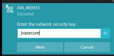
3 . The connection does not have Internet Access and if a warning message appears asking to “Remain Connected”, select Yes.
4 . Smart phones may require the Mobile Data to be turned off.
5 . Open an Internet Browser (Chrome / Firefox recommended).
6 . In the address bar, enter “192.168.4.1”.

The Virtual Keypad page will be displayed. On some devices this page may need to be refreshed once to download all components to the device.
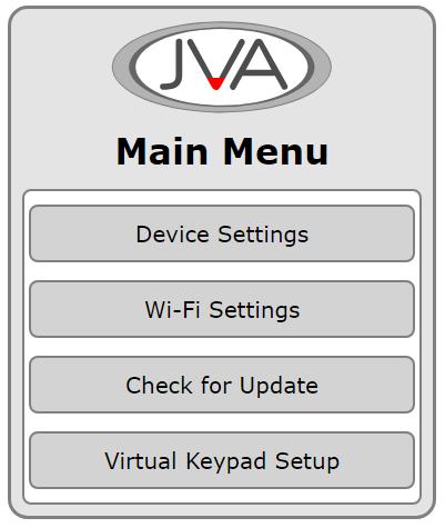
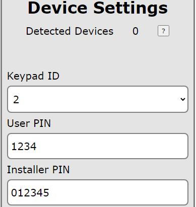
The device settings page contains the Input and Output configuration options. The Keypad ID option is also updated here.
.1
This is the number of devices the Wi-Fi Gateway has detected on the Keypad Bus. Press the ? to see a list and description of these. If the list does not match the site, press the Clear Detected Devices button at the bottom of this menu.
3 .1 .2 Keypad
This device acts as a Keypad to control the devices connected on the Keypad Bus. If no other Keypad devices are connected to the Bus, leaving this at ID 2 is a decent option. All Keypad devices must have a unique Keypad ID .
3 .1 .3 User PIN
This needs to be changed to the User PIN on the site to Arm/Disarm the Wi-Fi Gateway using a Keypad.
3 .1 .4 Installer PIN
This needs to be changed to the Installer PIN on the site so that Installer PIN commands are recognised correctly. This is necessary for Menu Driven Programming using the 4-line Keypad or Touch Keypad.
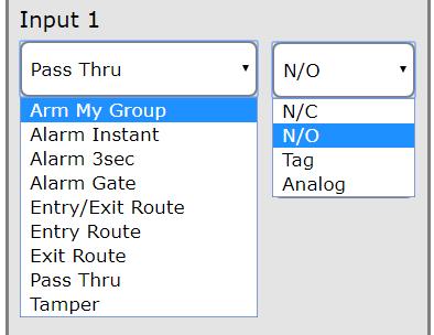
All Alarms are Latched (unless otherwise stated). The Alarms require the Wi-Fi Gateway to be Armed (through CR, Keypad) before they will activate. Latched alarm are cleared when Disarmed or Cleared through CR or a Keypad .
Arm My Group
Alarm Instant
Alarm 3sec
Alarm Gate
Description
The Input will send an Arm All/Disarm All command to the devices connected to the Keypad Bus.
An Input Alarm will trigger on Input Activation.
An Input Alarm will trigger after 3 seconds of continuous Input Activation.
The Input will trigger on continuous Input Activation for the Gate Time value.
Entry/Exit Route Combined Entry and Exit route system.
Entry Route When activated, the Entry Time starts to count down. The Alarm will trigger if the timer reaches zero and the Gateway is not disarmed. This allows someone to enter the site through a dedicated path and access a keypad to disarm without triggering the alarm.
Exit Route
When the Input is configured as Exit it is“bypassed” for the Exit Delay after the Gateway is armed. This allows someone to arm and then exit the site through a dedicated path .
Function Description
Pass Thru The value of the Input is passed to Cloud Router.
Tamper (24hr) A Tamper Alarm will trigger on Input Activation. Alarm Instant 24hr (24hr) This alarm is not latched. It will follow the Input state allowing an alarm that does not require clearing through CR, or a Keypad.
Function Description
N/C
N/O
The Input is Normally Closed. Activation when Open.
The Input is Normally Open. Activation when Closed.
Tag Activation toggles ON/OFF when the Input changes momentarily.
Analog
The Input can be configured to measure a 0-10Vdc voltage and pass this through to Cloud Router.
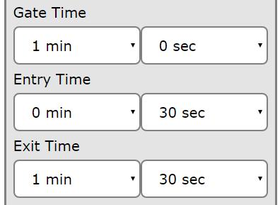
The Input timers are configurable to the second. This provides simple flexibility through an easy to use drop-down interface.
Function Description
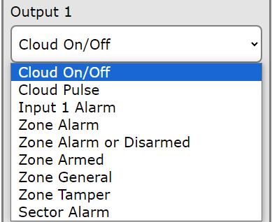
Cloud On/Off
Cloud Pulse
Input Alarm
Zone Alarm
Zone Alarm or Disarmed
Zone Armed
Zone General
Zone Tamper
Sector Alarm
Zone Mains Fail
The output is manually controlled through Cloud Router
This is a pulsed output that is manually controlled through Cloud Router
The output will trigger if the Input Alarms
The output will trigger based on the Alarm Information from a device connected to the Keypad Bus
The output will trigger based on the Alarm Information from a device connected to the Keypad Bus. If the device is Disarmed, it will also trigger
The output will trigger depending on Arm state of the device connected on the Keypad Bus
The output will trigger if the device connected on the Keypad Bus indicates a General Alarm
The output will trigger if the device connected on the Keypad Bus indicates a Tamper Alarm
The output will trigger if the connected ZM20/ZM50 device indicates the Sector is in Alarm.
The output will trigger when the selected zone indicates a mains fail trouble
Function Description
Zone Battery
Low/Bad
Zone Gate Alarm
3 .1 .8
The output will trigger when the selected zone indicates either a Low Battery or a Bad battery trouble
The output will trigger when the selected zone indicates its gate input is in alarm
Output Options - Input Alarm
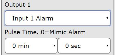
A pulse time can be selected for an Input Alarm. This allows the output to automatically reset after the selected time. If the time remains at 0, the output will mimic the Input Alarm State.
As the “Instant Alarm 24hr” function is not a latched alarm, setting a pulse time will ensure this is effectively latched for this pulse time.
3 .1 .9
Output Options - Zone Alarm
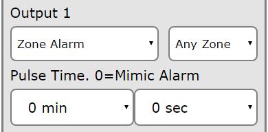
When the output is configured as a Zone Alarm, the choice of the specific zone is made available. If the Any Zone option is chosen then the output will trigger if any connected zones indicate the specific alarm type.
A pulse time can be selected for a Zone Alarm. This allows the output to automatically reset after the selected time. If the time remains at 0, the output will mimic the Zone Alarm State.
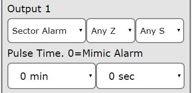
When the output is configured as a Sector Alarm, the choice of the specific zone and sector is made available.
A pulse time can be selected for a Sector Alarm. This allows the output to automatically reset after the selected time. If the time remains at 0, the output will mimic the Sector Alarm State.
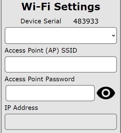
The Wi-Fi settings pages allows the JVA Wi-Fi Gateway to connect to a 2.4GHz Access Point (AP) to transfer data to Cloud Router.
The Scan button will start a search for nearby Access Points and these will be displayed in the list. The signal strength of each AP will be listed next to the SSID. When comparing APs, the smaller dB value indicates a stronger signal. For example -56dB is stronger than -89dB. Select the SSID from the list and then enter the AP password into the box. If you need privacy when entering the password, click on the eye icon next to the box.
Press the Connect button to complete the process. The Gateway will restart and the PC/Phone will be disconnected. After the restart, re-connect to the Wi-fi Gateway to again access the VKP again. This page will now display the IP Address that has been assigned by the Access Point.
The AP Password will now be hidden, and will display “Not The Password” if it is made visible by clicking on the eye icon.
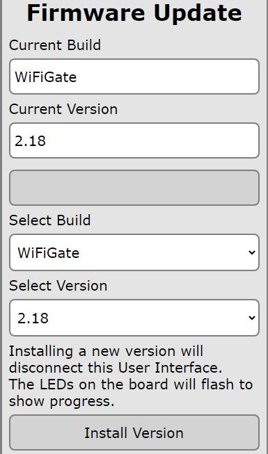
The Update system requires that the Wi-Fi Gateway is connected to the Internet.
When this page is opened the system will automatically check if a newer version is available. The “Select Version” box will be updated with the latest version that can be Installed by pressing the “Install Version” button.
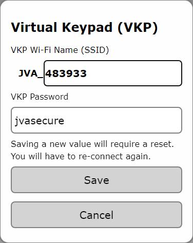
The VKP Wi-Fi Name (SSID) and VKP Password can be changed. This affects the Virtual Keypad when using the Wi-Fi Access Point. It is good practice to change the Password from the default value of “jvasecure” to stop unauthorised configuration of these devices. If either the Name or Password is changed, the QR code connection to the VKP will no longer work. Changing the SSID Name can be useful to “Name the Location” instead of relying on the default “JVA_[Serial Number]” SSID. Any change to these settings will trigger a reset of the device and as the AP details have changed, a new Wi-Fi connection will need to be established to access the Virtual Keypad again.
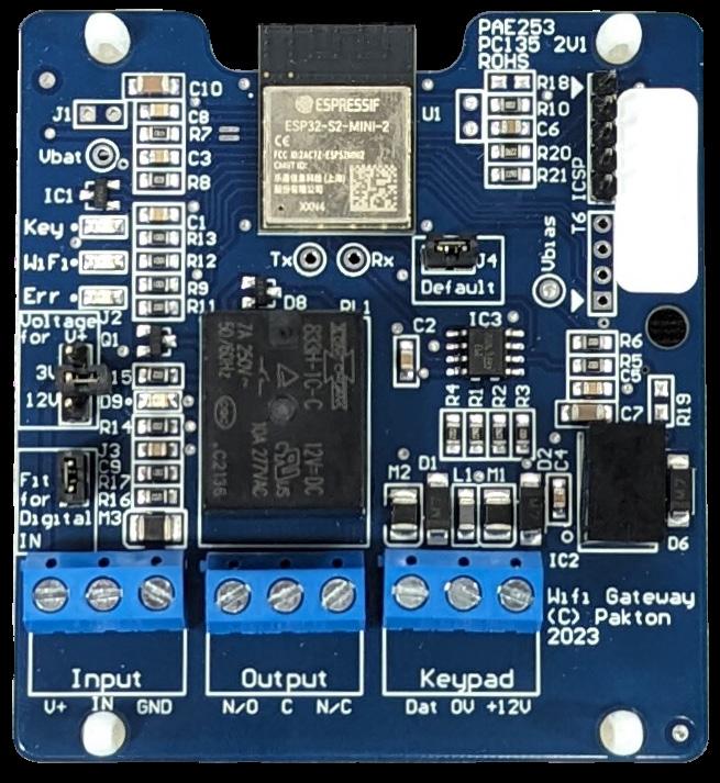
This black jumper/shunt is located in the middle of the board. To return the Wi-Fi Gateway to factory defaults, remove the shunt and power-cycle the board. This will reset all settings to default and all detected devices will be cleared .
Fit the J4 jumper/shunt back onto both pins after 5 seconds to ensure that new settings are remembered.
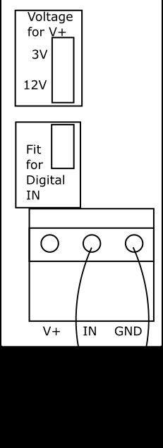
Dry Contacts Pull down to ground

0-10V analog signal
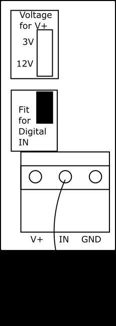
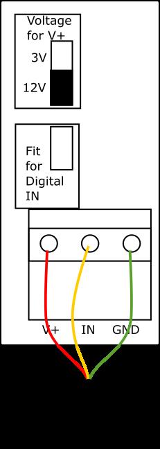
Water Sensor
The normal state of the output relay is de-energized. When the relay is energized, the LED to the left of the relay will turn on to indicate this state.
LED Information WiFi
1 Flash - Access Point is read for connection
2 Flash - Device connected to Access Point
3 Flash - Connected to LAN via Wi-Fi
Key Data is seen on the Keypad Bus
Err This is the Error LED
Manufactured for JVA by Pakton Group
The JVA logo is trademark of JVA Technologies Pty Ltd PTE0248 User Manual Version 23

www. jvA-fEncE.com