DENG
Selected
Portfolio
2017 - 2023

I am still asking myself what is architecture? And I should always think about the question. Architecture to me, has always been more than just designing a space or constructing a house. It is a subject that combining the knowledge of sociology, anthropology, psychology, environmental science, economic, ecology and even more subject fields. As an architect, what we can do is through out our research and limited study of those knowledge to create a spatial interaction, to endow the architectural meaning and response to that knowledge. Architecture has unlimited potential for me to dig, it contains millions of permutations and combination, and the difference between an architect and other people is that we can recognize these potentials with a unique spatial vision, then feedback to the sociality by using architectural language. My design projects have close connection with the sociality issue, and I also hope my design can show some sociological reflection in it, then after those thinking, the form of the space and architecture have naturally shaped.
CONTENTS 01 FROM URBAN, FEED URBAN | Renovation of 7 Penn Plaza INTER- | Community Centre THE NEUTRAL ZONE | UN Communication Building 04 03 02 NAKAGIN TOWER: RECONTEXTUALIZATION IN MEDIA ERA | Residence 05 LIFE OF ART | Art Centre 06 FROM PLASTIC | Thesis

01 FROM PLASTIC
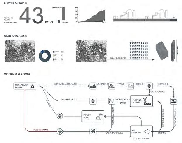
| Research Work | Co-work with Yixuan Li Thesis Research | Fall 2021 | Syracuse School of Architecture Instructor: Yutaka Sho, David Shanks, Nina SharifiThe thesis attempts to conceive a new ecology, where architecture helps waste plastics incorporate with emerging technology and building forms. The goal of our design is to imagine a relationship between human and plastics in the future, and further apply recycled plastics in architectural artifacts that form occupiable spaces.
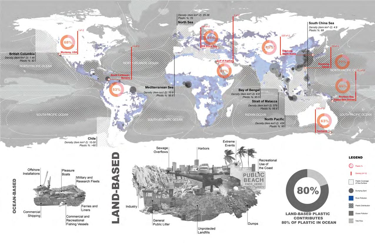
The rapid formation of a globalized market divides the world into roughly three parts: production, consumption, and waste accumulation Developed countries are transporting large amounts of waste to developing Asian countries because of technical cost of recycling plastics. In 2017 alone, the U.S. sent four hundred thousand metric tons of garbage to China. Due to the backwardness of the developing countries’ consciousness and technological shortcomings, almost 70% of the garbage eventually circulated through the surface to the ocean to form a garbage island. In order to seek the role of architects in the global dilemma, the research and availability of marine debris materials have become the key index of the problem. Among them, plastic is a material that accounts for up to 65% of marine garbage
Considering the high degree of recyclability of plastics, its ecological chain should be a high-circulation model. However, in the process of studying its ecological chain, almost every link of it has caused the production of various wastes, and it is closely related to the production of marine debris. A large amount of plastic is decomposed in the movement of the ocean and becomes microplastics, which enter the food chain and endanger all living things.
Among all the ways in which plastics are used, the existence period of plastics in construction is the longest, often reaching 30-60 years. How to lock plastics and use them in buildings may become a possible way to form a closed loop for the existing ecological chain of plastics.
Area of Garbage Patch in the Ocean (km^2)

Horn, TortoiseshellEarly Synthetics, Casein, Bakelite, UreasPlastics as an IndustryPlastics in War Textiles, Fashion, Toys, Domestic usesColour and DesignHigh Performance Plastics Nano Technology, Airbus A380, iPod Earliest1990-19291930s1940s1950s 1960s & 70s1980s & 90s 2000s & Future 0 50 100 150 200 250 300 350 400 Global Plastic Production (Mil/Mt) 1960 First Reports of marine plastic debris impacting on marine species were published MARINE PLASTICS GLOBAL POLICY TIMELINE *Global Programme of Action for the Protection of the Marine Environment form Land-based Activities 1972 London (Dumping) Convention 1973 MARPOL Convention 1975 London Convention comes into force 1978 MARPOL Protocol adopted 1979 CMS Convention 1983 MARPOL 73/78 Convention enter into force 1984 First Honolulu conference 1988 Annex of the Marpol Convention enters into force 1989 Second International Conference on Marine Debris (Honolulu) Basel Convention 1992 Basel Convention enter into force Concention on Biological Diversity 1993 Convention on Biological Diversity enters into force 1994 Third International Conference on Marine Debris (Miami) United Nations Convention on the Law of the Sea (UNCLOS) enters into force 1995 GPA* established 1996 London Portocol is adopted 2000 Fourth International Conference on Marine Debris (Honolulu) 2004 Stockholm Convention enters into force 2013 Revised MARPOL Annex V 2015 G7 Action Plan 2016 UNICPOLOS on “Marine Debris, Plastics and Microplastics” 2025 Commitment significant reduction in marine debris by 2025, as agreed under the Rio+20 Convention 2030 Achienement of the Sustainable Development Goals 2014 UNEA-1 resolution 2011 MARPOL Annex Fifth International Conference on Marine Debris (Honolulu) producting the Honolulu commitment/strategy 2012 Global Partnership on Marine Litter Manila declaration Rio+20 commitment to reduce marine debris 2005 UN General Assembly delivers resolution on marine plastic pollution 2001 Stockholm Convention 1974 UNEP Regional Seas Programme launched 0%2%9%16%19% 1284 First recorded mention of The Horners Company of London, with horn and tortoiseshell as the predominant early natural plastic. 1900 1930 1940 1950 1960 1970 1970s 1980s 1990s 2000s 2010s 1980 1990 2000 2010 2018 1941 Whinfield and Dickson, of the Calico Printer's Association of Manchester, patent "polyethylene terephthalate" (PET); followed by the creation of the first polyester fiber called Terylene. 1942 ‘Super Glue’ (methyl cyanoacrylate) first discovered by Dr Harry Coover, Eastman Kodak. 1943 First pilot plant for polytetrafluoroethylene (PTFE) to be marketed under trade mark ‘Teflon’ 1945 The production of LDPE the Sqezy bottle by Monsanto caused rapid expansion of the industry, with containers produced to replace glass bottles for shampoos and liquid soaps. 1947 Formica melamine faced decorative laminates introduced into the UK. 1948 Acrylonitrile-butadiene-styrene (ABS) produced. George deMestral invents Velcro, patented 1955. Introduction 12” long playing records made from polyvinyl chloride (pvc). 1949 First Airfix self-assembly model initially made of cellulose acetate and later polystyrene. High impact polystyrene introduced as commercial plastic. Launch in US of Tupperware made from low density polyethylene. ‘Lycra’ based on polyurethane, invented by DuPont. 1950 The polyethylene bag makes its first appearance. Introduction of acrylonitrile-butadiene-styrene (ABS) copolymers. ICI opens new factory at Redcar to produce Terylene. 1951 Festival of Britain. 1953 Commercialisation of polyester fibres introduces the concept of ‘drip dry’ and ‘non-iron’. 1954 Polystyrene foam (introduced by Dow Chemical Co.) 1955 First production of high density polyethylene. 1957 The hoop is reinvented as the Hula Hoop by Knerr Medlin, Wham-O Toy Company. First production of polypropylene by Montecatini using Ziegler-Natta catalysts. 1958 First production of polycarbonates (Bayer and General Electric). Lego patents its stud and block coupling system and produces toys of cellulose acetate, later Acrylonitrile- butadiene-styrene polymer. 1959 Barbie Doll unveiled by Mattel at American International Toy Fair. 1960 Introduction water based acrylic paints Ethylene-vinyl acetate co-polymers launched by DuPont. 1962 DuPont launches polyimide films and varnishes. Silicone gel breast implants pioneered successfully. 1965 Kevlar® is first developed by DuPont. 1966 Blow moulding of fuel tanks introduced. 1967 Polyvinyl chloride (PVC) ‘Blow’ chair designed by Scolari, De Pas and Lomazzifor manufactured by Znaotta. 1969 Neil Armstrong plants nylon flag on the moon. 1970 First Yellow HDPE pressure pipes for gas introduced into UK by Wavin/British Gas. 1980 First production of linear low density polyethylene. First Blue HDPE pressure pipes for potable water introduced into UK. 1982 First artificial heart made mainly polyurethane, introduced implanted in a human. 1983 The slim plastic Swatch watch made of 51 mainly plastic components. ICI and Bayer launch PEEK, PPS (polyphenyene sulphide), and PES (polyether sulphone). 1987 BASF Germany produces a polyacetylene that has twice the electrical conductivity copper. 1988 Introduction of triangular recycling symbols relating to plastics. 1989 First light-emitting polymers (poly-ethyne) discovered in Cambridge. The Gravimetric Batch Blender invented by Steve Maguire revolutionising the industry and bringing affordable gravimetric blending processors. Bullet Proof Polymer Scientists at Rice University, Texas have created new super polymer material that can stop 9mm bullet and seal the hole behind it. Plastics Blood Developed by the University of Sheffield to mimic haemoglobin, for use in trauma situations where blood is needed quickly. Plastic Solar Cells polymer solar cell that can produce electricity from sunlight by the photovoltaic effect provides a lightweight, disposable and inexpensive alternative to traditional solar panels. Implantable Polymers Medical grade and implantable biomaterials such as PEEK will be used in neurological applications to help control epilepsy, Parkinson’s disease and brain trauma. Commercial Space Flights Lightweight carbon composite materials will be crucial in the realisation of sub-orbital tourist spaceflights. 3D Printed Body Parts Using plastic materials such as PMMA car parts can be printed home and doctors can produce replica livers or kidneys for transplant patients. Flexible Plastic Screens Organic light-emitting diodes are placed on plastic foil to create electronic devices with flexible displays. Driverless Cars the future all driverless vehicles will be almost entirely constructed from plastic parts due to the light weighting properties they provide. 1990 ICI launches Biopol, the first commercially available biodegradable plastic. 1991 Dyson’s vacuum cleaner launched Japan. 1994 Smart car with lightweight flexible integrally coloured polycarbonate panels introduced. 1998 Free standing Zanussi Oz fridge, with insulation and outer skins made in one process from polyurethane foam introduced. 2000 Nano-Technology applied to polymer and composit applications. First commercial metallocene catalysed polyolefins introduced. 2001 iPod dreamed up by Tony Fadell, an independent inventor, developed by Apple Computers. 2005 NASA explores the advantages of polyethylene based material RFX1, as the material for the spaceship that will send man to Mars. Polycond project established to look at the potential of conductive polymers. 2008 Airbus 380, comprising 22% carbon-fibre reinforced plastics flies into Heathrow. 2009 Boeing 787 (nicknames 'Boeing's Plastic Dream') comes into service, its skin is made up of 100% Plastic composites with plastic making up 50% of all materials in the plane. 1973 Polyethylene terephthalate beverage bottles introduced. 1976 Plastics in its great variety of forms becomes the most used type of material the world. 1977 Polyaryletheretherketone (PEEK) was first prepared by ICI. 1979 Introduction of first commercial mobile/ portable ‘phones. First PVC-U double glazed windows installed. 1956 Reliant Regal 111, first commercially successful all glass-reinforced-plastic bodied car goes on sale. Eero Saarinen’s Tulip Chair launched, consisting seat made of glass-fibre-reinforced plastic. DuPont files patents for first acetals (POM). 1940 Use of polyethylene radar. First production PVC in UK. DuPont introduces polyacrylonitrile (PAN), an early engineering product. 1850 First submarine telegraph cable gutta percha laid between Dover and Calais. 1862 Display of Parkesine, predecessor of celluloid (cellulose nitrate), at the 1862 Great International Exhibition in London. 1872 Hyatt brothers patented first plastics injection moulding machine. 1880 Fashion for long hair leads to cellulose nitrate replacing horn as the preferred material for combs. 1885 George Eastman Kodak patents machine for producing continuous photographic film based on cellulose nitrate. 1890 Thermoforming introduced and used to make babies rattles from cellulose nitrate. 1892 Viscose silk (rayon) developed by Cross and Bevan (Chardonnet Silk). 1898 Beginning of mass production of rpm gramophone records from shellac. 1899 Krische and Spittler Germany awarded patent for Casein Plastic from milk. Artefacts introduced at the Plastics Universal Exhibition 1900. 1909 Casein plastics, derived from milk, developed by Erinoid. 1910 Stockings made of viscose (CA) begin be manufactured in Germany. 1915 Queen Mary sees casein products the British Industries Fair and orders several pieces of jewellery made from 1916 Rolls Royce begins to use phenol formaldehyde in its car interiors and boasts about 1919 Eichengrun produce first cellulose acetate moulding powder. 1921 Beginning of rapid growth phenolic mouldings especially for electrical insulation, with addition of phenolic laminates in 1930. 1922 Staudinger publishes his work that recognises that plastics are composed of long chain molecules leading to Nobel prize 1935. 1924 Rossiter British Cyanide develops urea thiourea formaldehyde resins, subsequently commercialised as the first water white transparent thermosetting moulding powder. 1926 Harrods hosts first display of new coloured thermosetting plastic tableware produced by Brookes and Adams, The Streetly Manufacturing Company and Thomas De La Rue and Co. Eckert and Ziegler patent first commercial modern plastics injection moulding machine. 1929 Bakelite Ltd receives its largest ever order for phenolic moulding powder for the casing of the Siemens telephone. 1930 ‘Scotch’ tape, the first transparent sticky tape invented in US by 3M Company. 1932 Screw per-plasticisation injection moulding patented. 1933 BPF founded. Fawcett and Gibson at ICI discover polyethylene. Crawford ICI develops first commercial synthesis poly(methyl methacrylate). 1935 Troester in Germany produce first extruder designed for thermoplastics. Carothers and DuPont patent nylon. 1936 First production of aircraft canopies made from ‘Perspex’. 1937 Columbo and Pasquetti in Italy produce first twin screw extruder machine. First commercial production of polystyrene by IG Farben, Germany 1938 Full scale production of nylon fibre begins United States. First toothbrush with nylons tufts manufactured. Plunkett (DuPont) discovers PTFE. 1939 First commercial production of polyethylene in UK by ICI. Outbreak of war strategic stockpiles, plastics war. Discarded Incinerated Recycled 1 7 9 8 3 5 10 14 15 6 13 2 4 11 12 North Pacific Garbage Patch West 20,495 20,198 15,649 14,529 10,525 9,911 9,049 8,557 7,954 5,902 4,870 4,245 3,961 1,994 1,683 North Pacific Garbage Patch East West Atlantic Garbage Patch East Philippine Sea Patch South Atlantic Gyre Patch Indian Ocean Gyre Patch North Pacific Garbage Patch South East Atlantic Garbage Patch East Caribbean Sea Patch South Atlantic Gyre Patch South Philippine Sea Patch South Indian Ocean Gyre Patch Australia Sea Patch Korea Sea Patch Russia Sea Patch Great Pacific Garbage Patch South Pacific Gyre South Atlantic Gyre North Atlantic Gyre Indian Ocean Gyre 1 7 7 9 8 3 5 10 14 14 6 13 15 2 4 11 12
The existing building ecology is terrible. Almost 70% of plastics end up in the environment and continue to harm nature. Recycling plastic is the most environmentally friendly way, and its utilization rate has been low due to cost and technical issues. Studies have shown that nearly 90% of plastics can be reused after recycling, but the number of times that they can be recycled is limited. The process of repeated processing and recycling also consumes a lot of resources. How to place recycled plastic in one place has become a problem. Looking at the life cycle of various uses of plastics, construction plastics are often the longest lasting. Considering the sustainability of plastics and the longevity of construction, trying to think about how recycled plastics exist as various elements in constructions may be the last step in the closed loop of plastics.
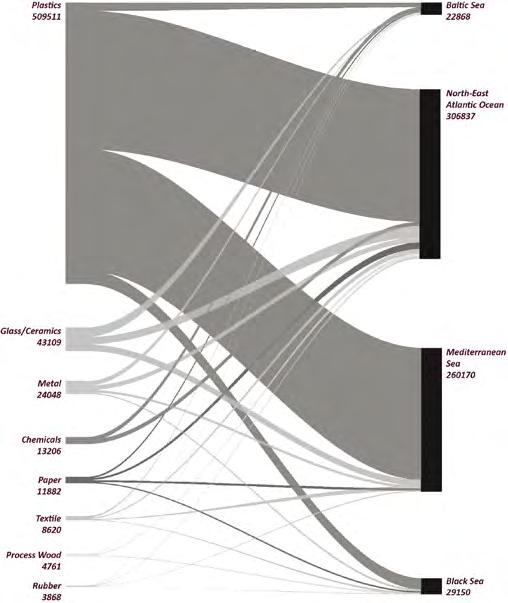
Plastic Flow
Potential of Plastic
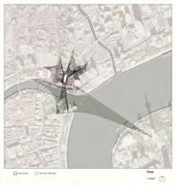
Potential Site
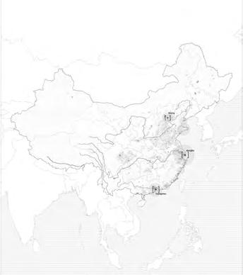
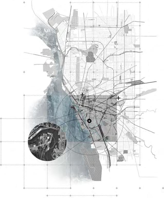
As the world's l argest producer of marine debris, we try to use China as a model to think about how to solve the problem of marine debris on land. From the perspective of population migration and density to analyze possible future major cities, the coast will be the main habitat in the future. We began to think about how to return the plastic waste they produced to them in a form that they can use in buildings.
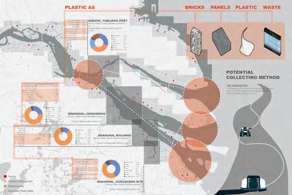
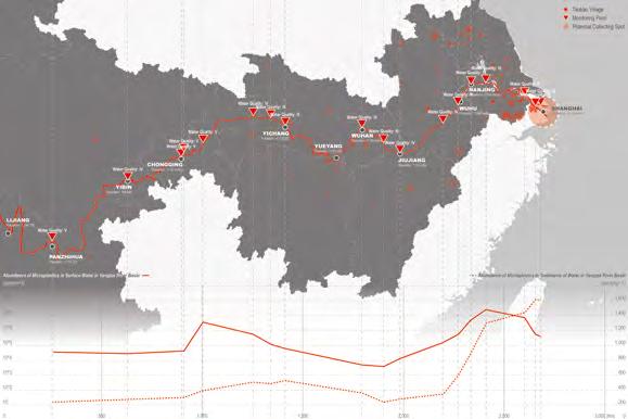
 Yangtze River Solid Waste
Shanghai Area Waste Condition
Yangtze River Microplastic Sediment
Future Population Migration
Yangtze River Solid Waste
Shanghai Area Waste Condition
Yangtze River Microplastic Sediment
Future Population Migration
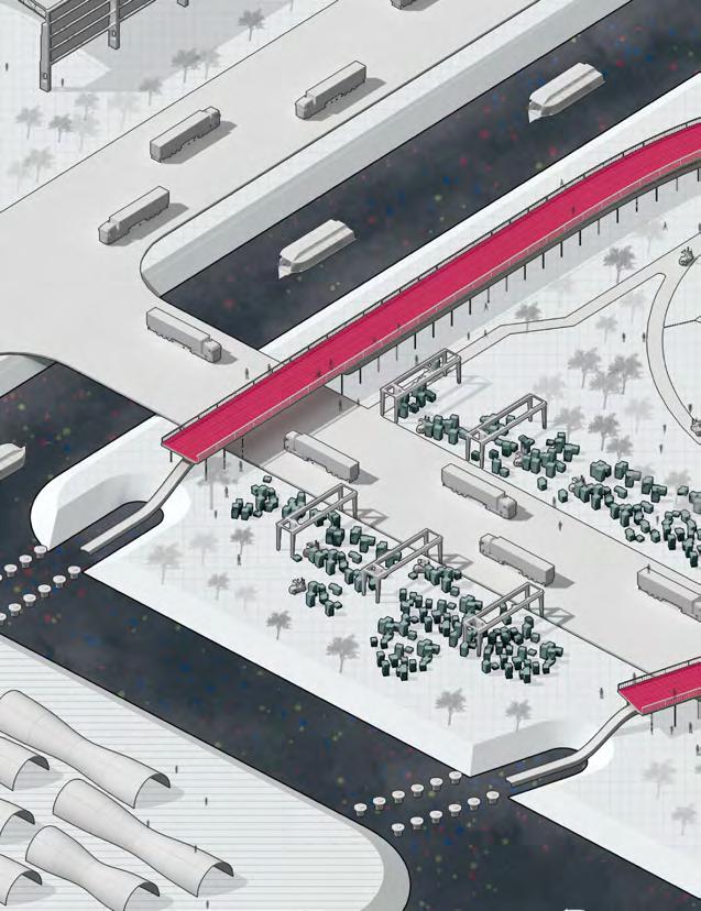
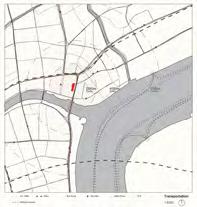
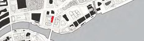
Site Selection - Malu
Site Analysis
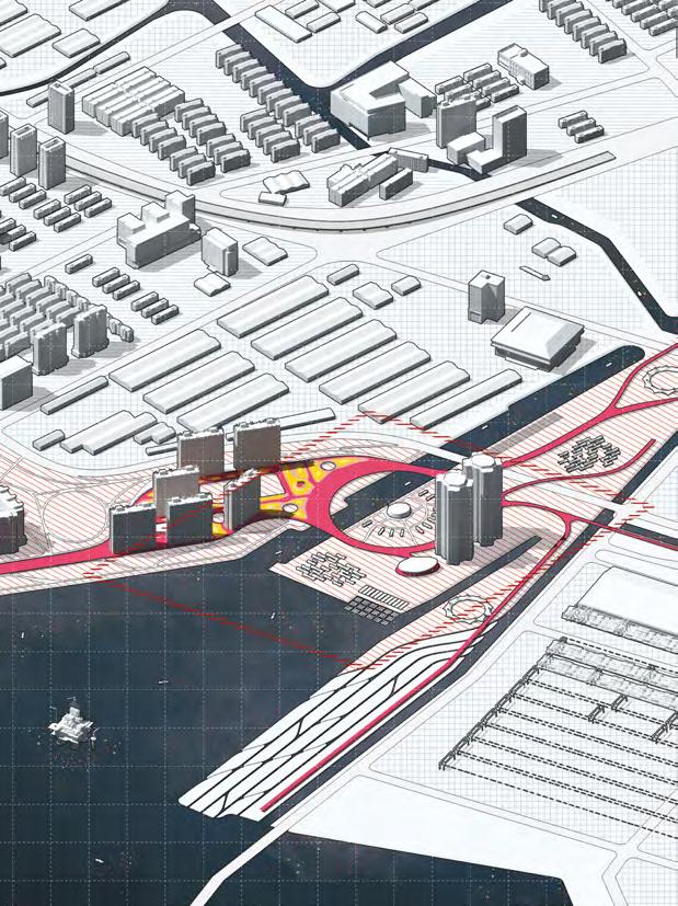
The design proposal not only played as an urban filter that aims to guard the final threshold and collect the possible flowing plastics in the river, but also attempts to utilize these materials to form a common media that incorporate within the existing urban context. As our diagrams of Shanghai urban planning analysis, the government is now attempting to transform this area into an urban public space with industrial heritage,
harbor cultural landscape, and leisure spaces. The river island, currently occupied by parking lots, is considered as an important urban block to exhibit the ambition of both public and government’s future plan to transform.
 Site Condition
Future Plan of Site
Purpose Plan System of Site
Site Condition
Future Plan of Site
Purpose Plan System of Site
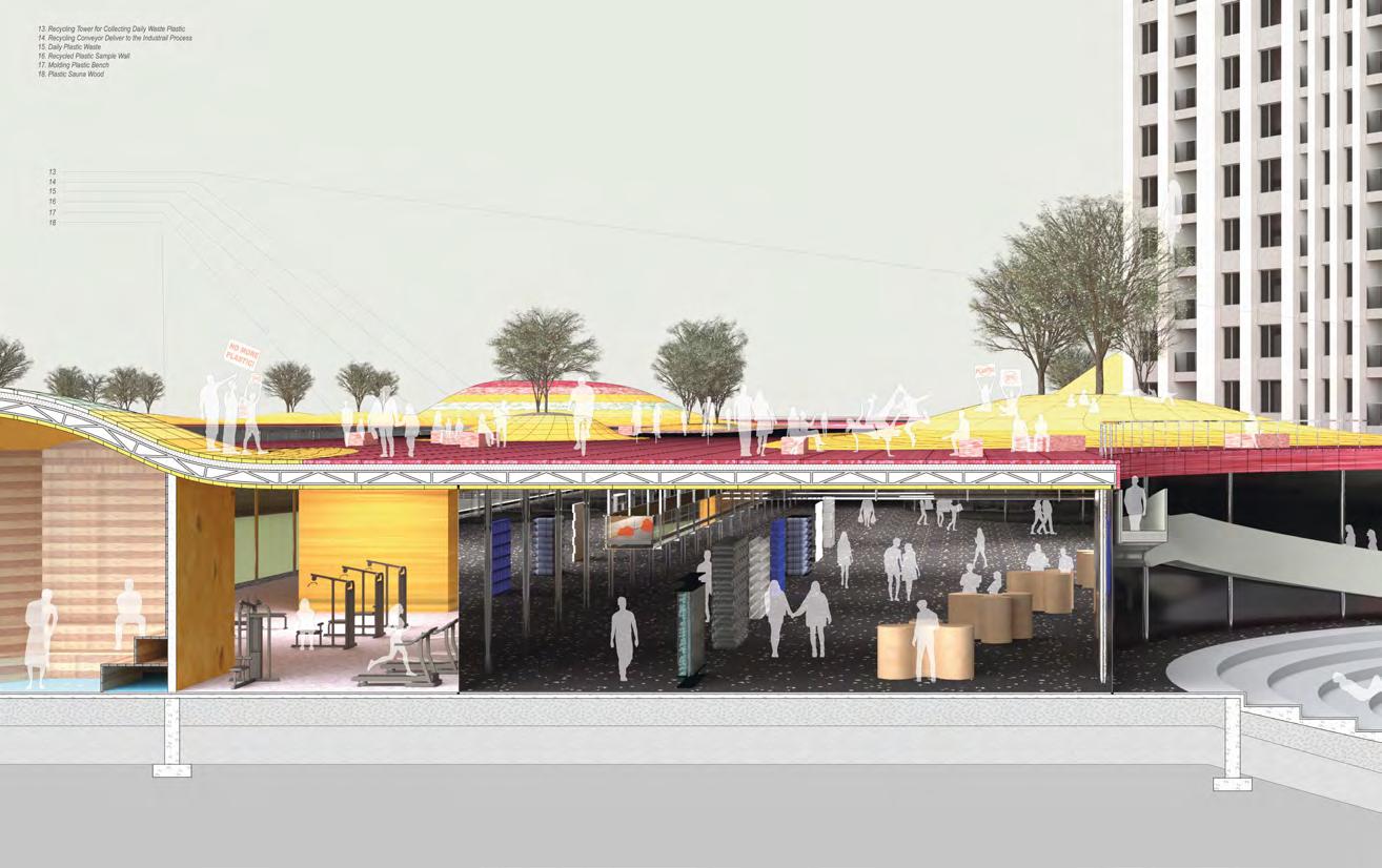
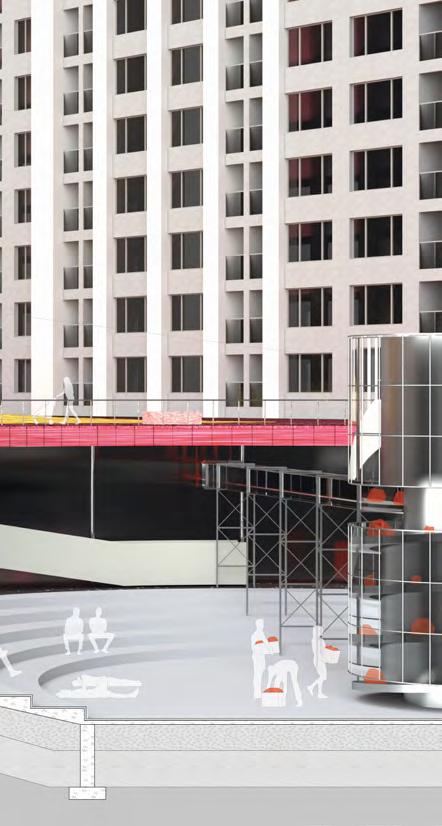
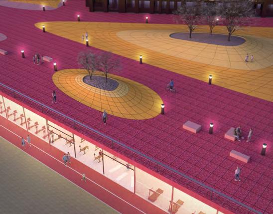
The designated complex would include recycling facilities, reactional space, public connections, and also the plastic museum. The plastic architecture of our design would be a product of accumulated plastics, working in the form of expanded surface, which aims to incorporate with existing site such as residential towers, industrial warehouse, and urban green ways, but also play as the medium to generate more public spaces such as playground, courtyard, and pedestrian walkway.
 Recycling System
System Overlook
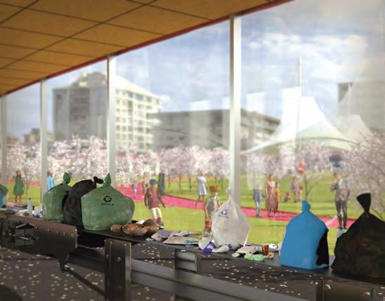
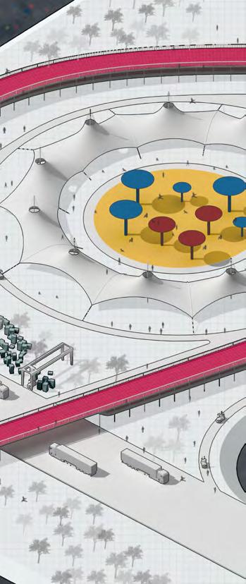
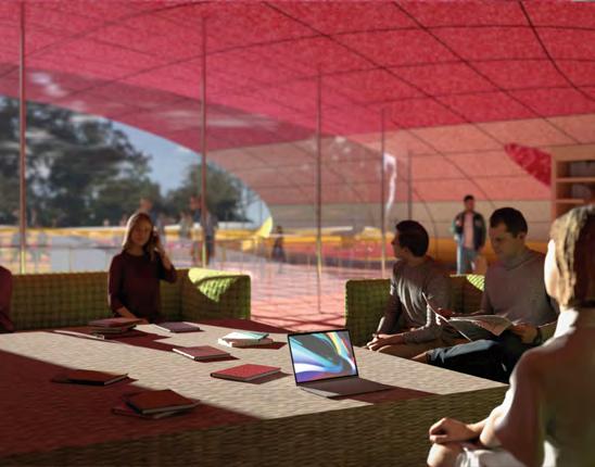
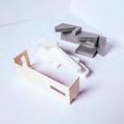
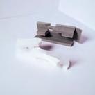
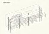
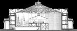
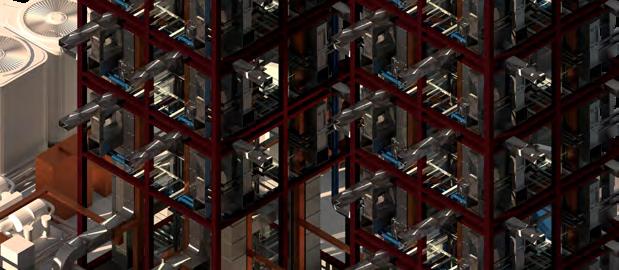
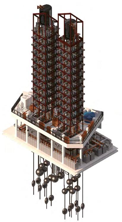
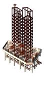
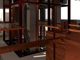
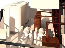
The attention for using plastic extends more than just on urban scale, but also the interior programs. This complex attempt to exhibit recycled plastics in a practical method, which enables people to watch the process of recycling waste materials and also use the product or furniture from them. Ideally, the whole project would be mostly made out of plastics except the required structure steels. As you can see in the detailed section, the main structure of this project is made out of steel, and the other things included such as ceiling panels, floor mat, and furniture are mainly made out of processed plastics. The different technologies such as compression, 3-D print, and injection molding enable plastics varies their forms to fit for various scales, programs, performances, and activities.
Collection System
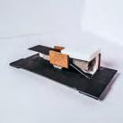
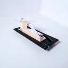
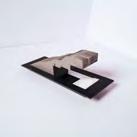
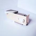
Recycleing Conveyor Render
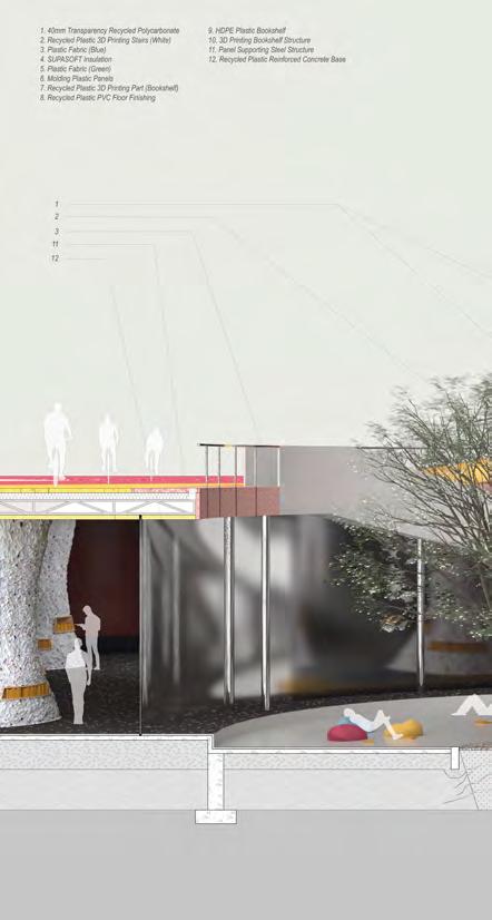
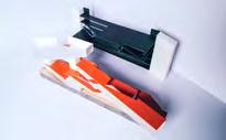
Detail Section aa’ Library Render Section aa’ a’ b’ Detail Section 1 Section aa’ a’ b’ Detail Section 1
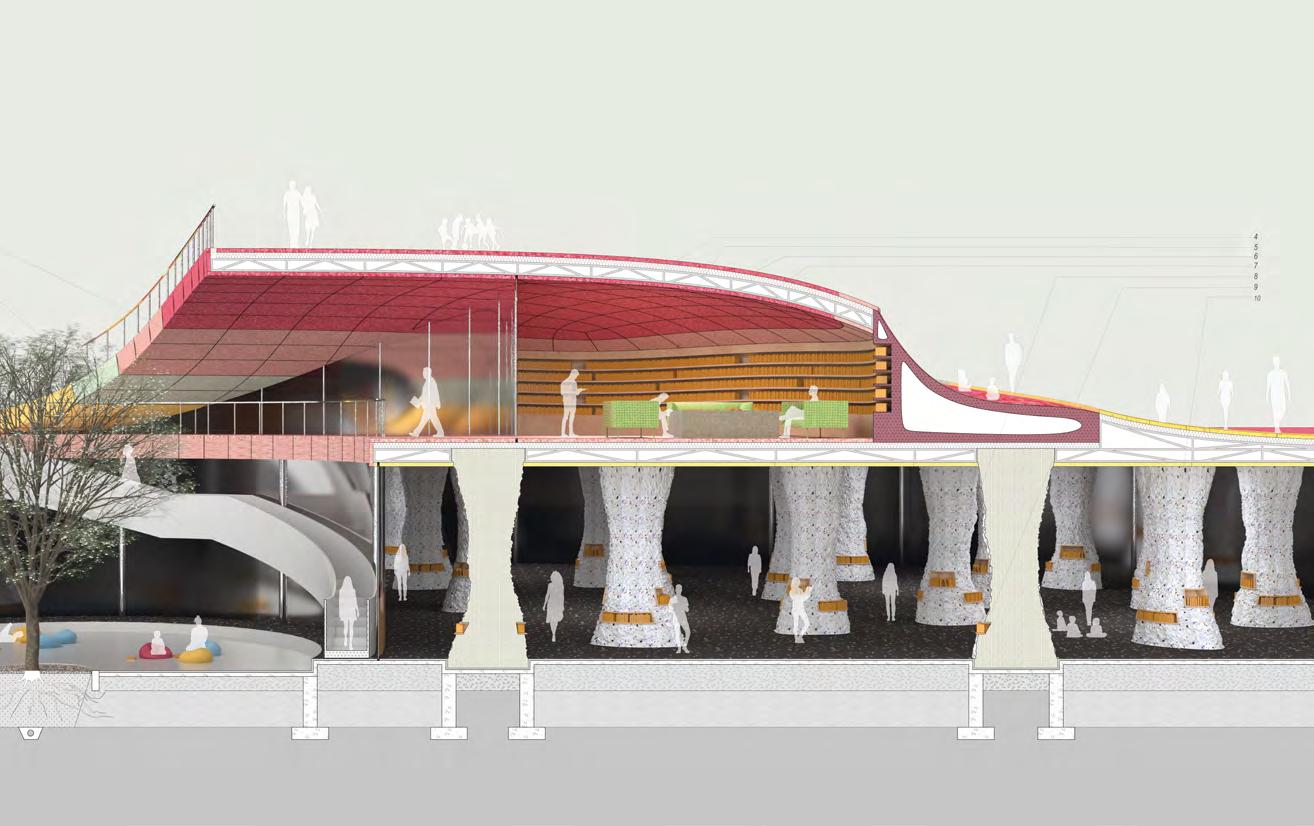
Detail Section bb’ Platform Night View Render Section bb’ 051020 40m Detail Section Section aa’ a a’ b’ Detail Section 1
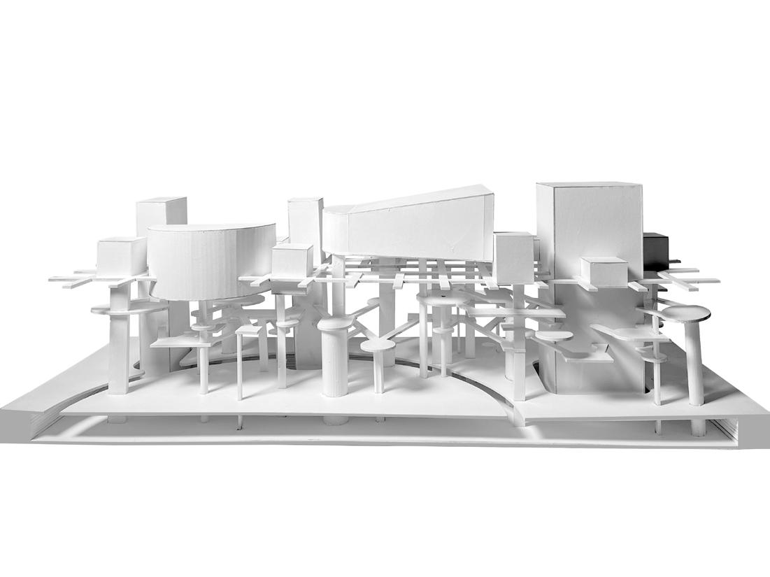
FROM URBAN FEED URBAN
| Design Work | Co-work with Xiangyi Deng Studio Work | Fall 2022 | Columbia University GSAPP Instructor: David Benjamin
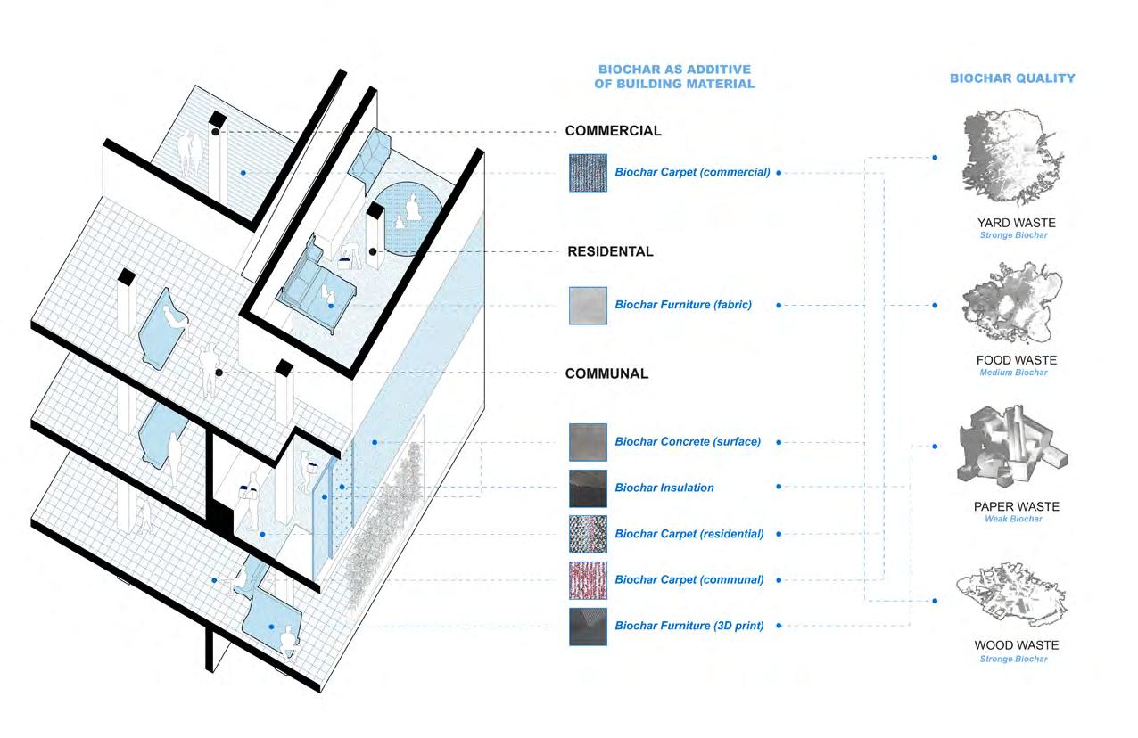
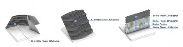
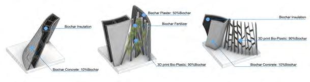
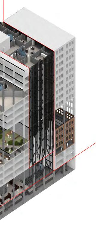
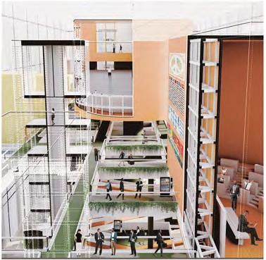
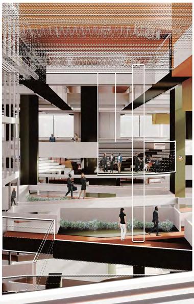
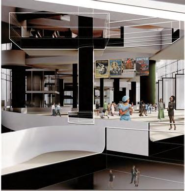
Municipal Solid Waste can be converted into biochar, the negative carbon additives, and its unique advantage include avoiding carbon emissions from waste transportation and burning while permanently storing carbon inside. Combining it with different building materials can lead to the possibility of a self-repairing building that redefines metabolism . The project will design a new trash chute system that collects and converts wastes during the operation of buildings into biochar-included materials as products, which forms a closed loop circulation economy around MSW that encourages a new lifestyle about trash sorted and shared living. MSW collected from surrounding buildings will be re-exported as biochar products to make a bigger influence. This infrastructural system works both at building-scale and urban-scale, connecting buildings, forming public skywalks, and leading to new types of aesthetic spatial qualities around the trash chute system
02
Urban MSW Pyrolysis Process & Carbon Cycle vs. Biochar Cycle
Potential of MSW
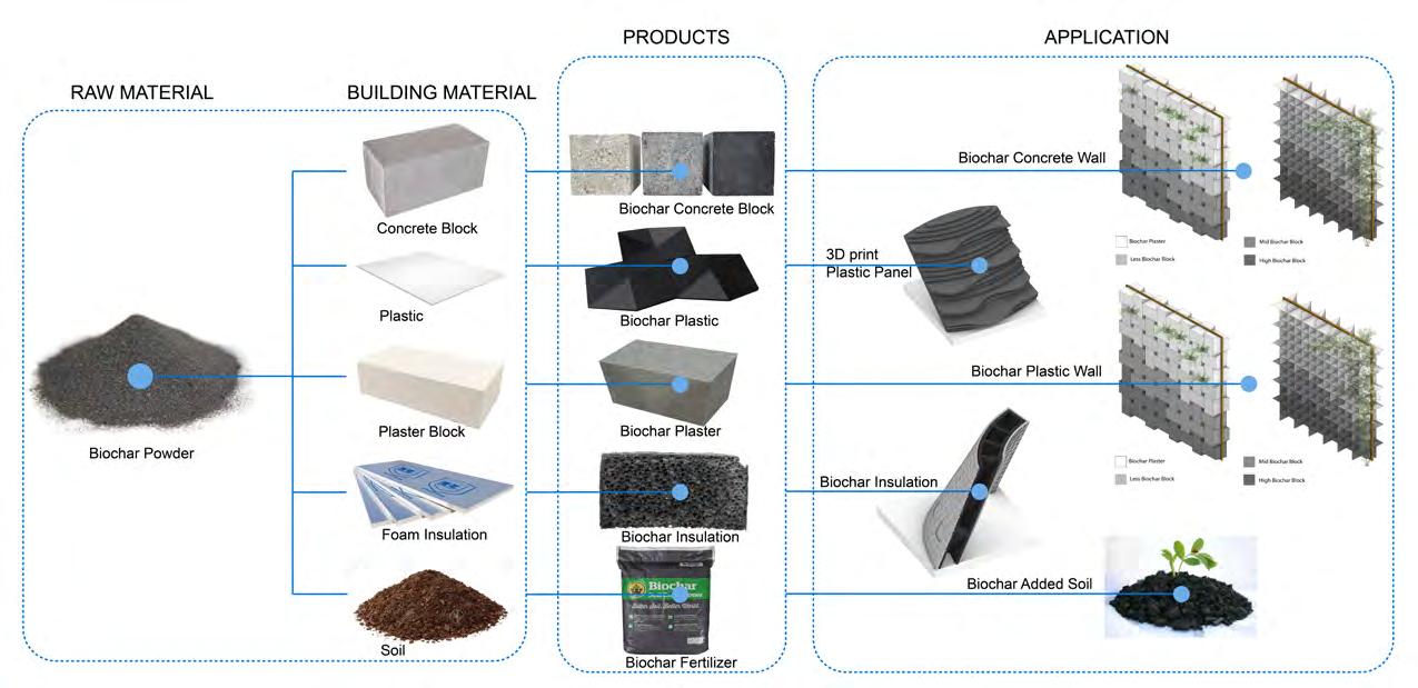
Biocahr Building Material & Application
More than 6 0 percent of MSW have the potential to be converted to biochar, and they usually become landfills and composters in the current system, emitting a lot of carbon.
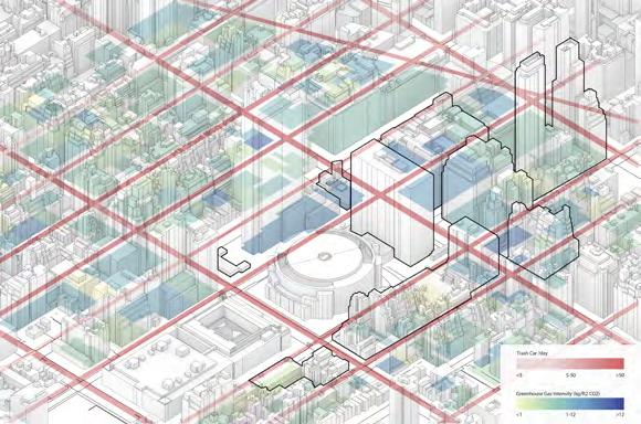
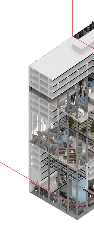
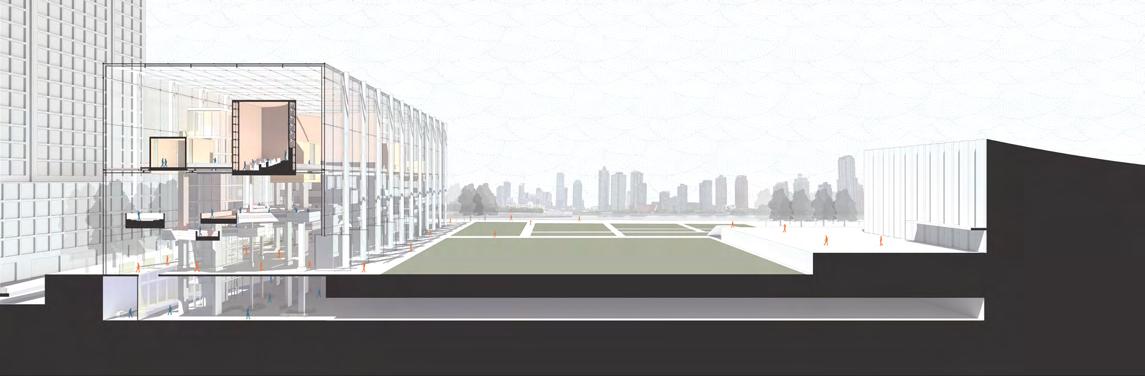
According to the construction plan, several buildings surrounding Penn Station will be demolished, 7 Penn Plaza is one of them. As one of the busiest places in NYC, we studied greenhouse gas emission of buildings on site and the trash truck density here. Both are very high, which means the attempt to reduce trash and emission in this area can be efficient.
7
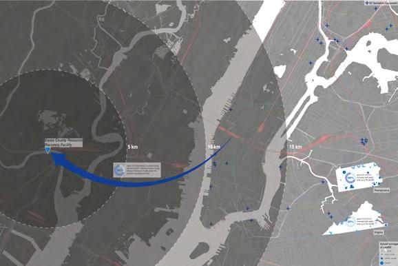
NYC MSW Transportation (World) NYC MSW Transportation (US)
Penn Plaza Study
System Purpose
Typology Study
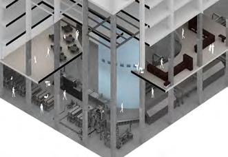
The system could work at a larger scale in the city as a new type of infrastructural system. Trash in surrounding buildings can be collected and transported through horizontal trash chutes to the central building and converted into biochar products. Those chutes are also designed to be skywalks that connect rooftop spaces in the community to create more public spaces in such a high-density area. In this way, the new Infrastructural System serves both functionally and aesthetically, and expands the concept of metabolism to a larger community scale.
System Purpose (Urban)
 View from Walkway
View from Roof Gardon
View from Walkway
View from Roof Gardon
 Public Gardon Gardon Level
Work
Office Common Space
Space
Building Phase
Office Level
Axon
Basement Work Space Basement Level Residential Level (Common Space) Residential Level (Room) Residential Trash Chute Residential Room
Ground Level Plan Basement Plan
Office Level Plan Residential Level Plan


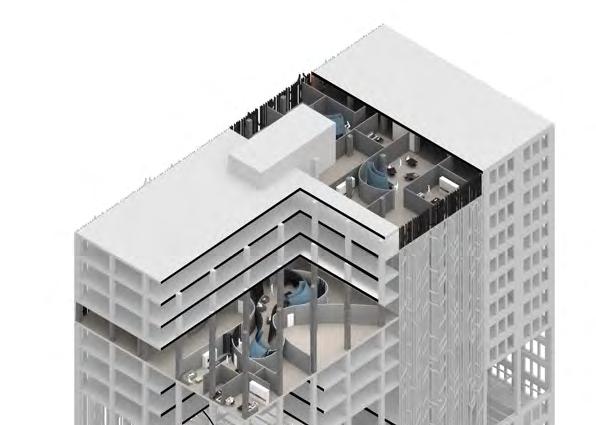
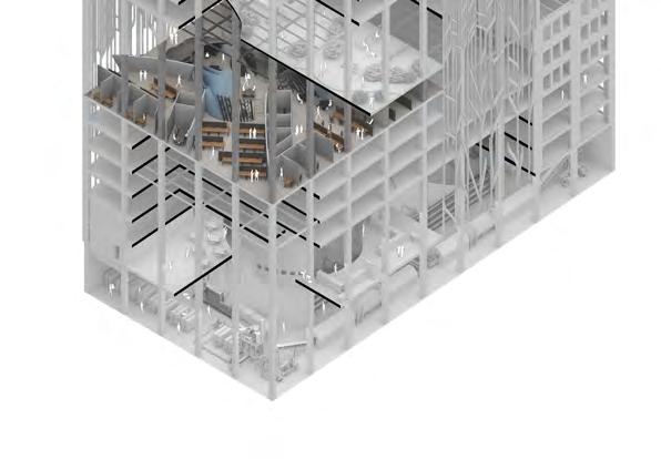
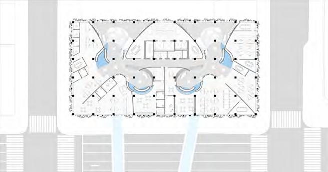
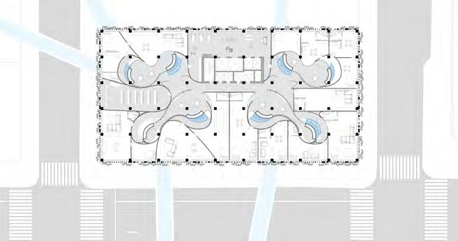
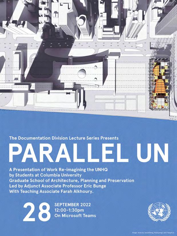
THE NEUTRAL ZONE
| Design Work | Co-work with Huanpeng Li, Yangxi Liu Studio Work | Summer 2022 | Columbia University GSAPP Instructor: Eric Bunge
“A world capital, or a temple of peace… It is too soon to use such fine phrases, non? The UN simply does not exist yet. The nations are not united. The UN is not proved. It is simply a poste de combat.”
 Le Corbusier, 1947
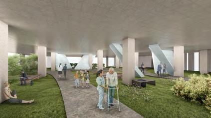
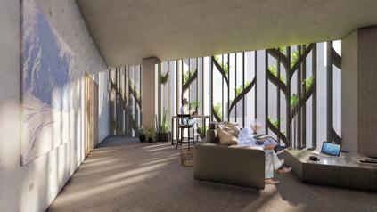
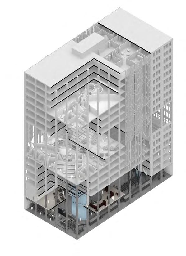
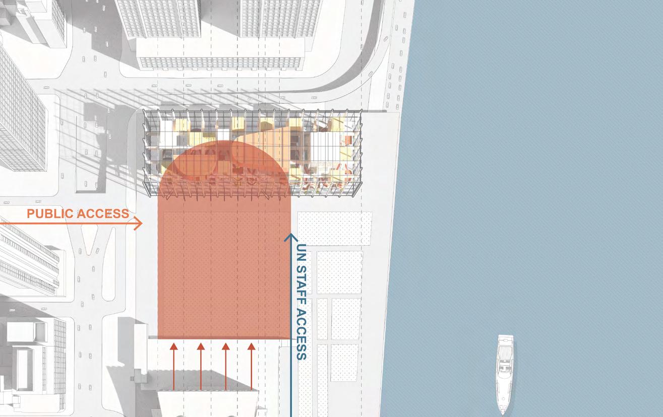
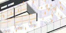
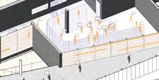
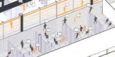
Seventy years later, the UNHQ exists; however, was the UNHQ ever completed? As with the environment or geopolitics, everything in the world is constantly changing, and so is the UN. As the UN’s mission and inner workings become more complex, we propose that it will require a compact and effective space that hosts conversations between different departments.
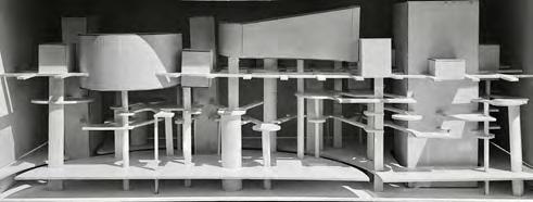
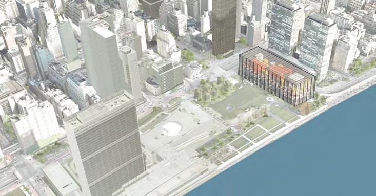
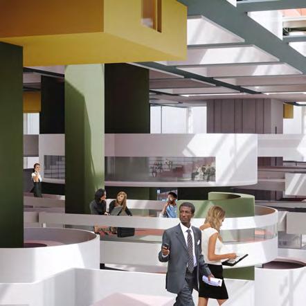
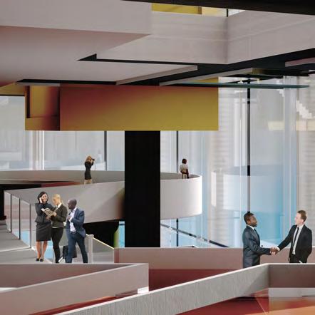
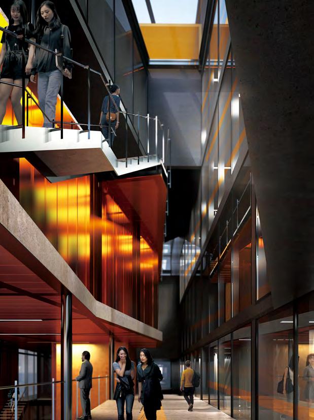
The project, The Neutral Zone, connects the original UNHQ to the northern part of the site to a new armature for inter-agency discussions and collaboration. The ground level is open to public visitors, per the original master plan. There is a visual connection between general visitors and UN staff as people look up to the zigzag grid of the second-level. The second level links multiple nodes of conversation platforms that facilitate cross-departmental conversations, also accommodating overseas UN agencies’ offices. The third and highest level is organized as a square grid of paths connecting various chambers and a common hall, hinted at when people look up from the ground level. The Neutral Zone aims to improve the foundation of the original UNHQ and encourage crossdepartmental dialogue. In this project, we accept the chaos of the world, and forge neutral relationships between different countries’ delegates, the UN, and the general public.
03
GRIDS
TOP TOP SECOND SECOND GROUND GROUND OVERLAY OVERLAY
VOLUMES
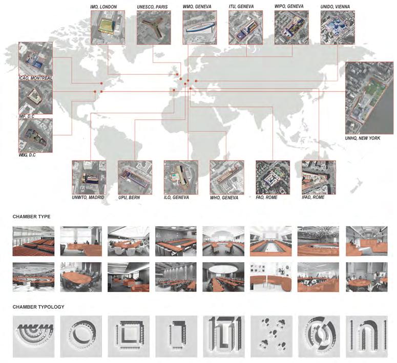
Map of UN Facilities & Chamber Typology Study
Design Strategy
Site Responce
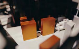
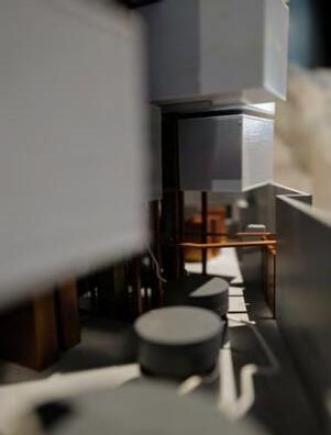
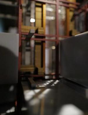
Bird’s-eye View
Conceptral Model
Ground Floor Plan Second Floor Plan 1 Second Floor Plan 2 Top Floor Plan
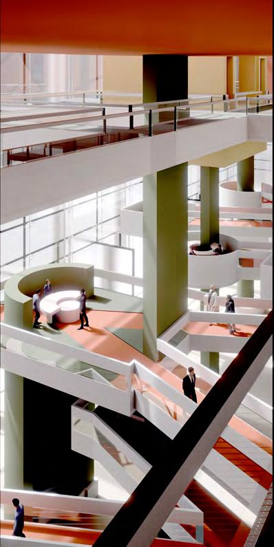
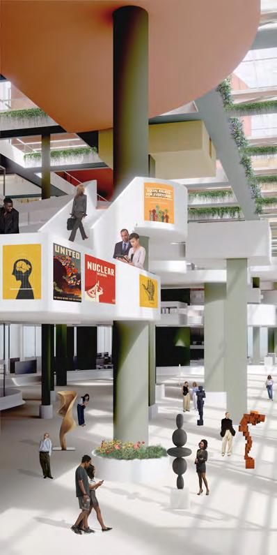
Overall Axon Interior View 1 Interior View 2
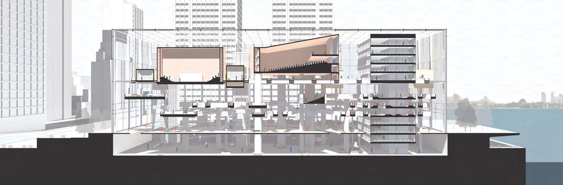
 West-East Section
South-North Section
West-East Section
South-North Section
 Ground Level Sectional Perspective
Second Level Sectional Perspective
Top Level Sectional Perspective
Ground Level Sectional Perspective
Second Level Sectional Perspective
Top Level Sectional Perspective
 Interior View 3
Interior View 4
Interior View 3
Interior View 4
| Design Work | Co-work with Zheng Fang
Studio Work | Spring 2021 | Syracuse School of Architecture Shanghai
Instructor: Fei Wang
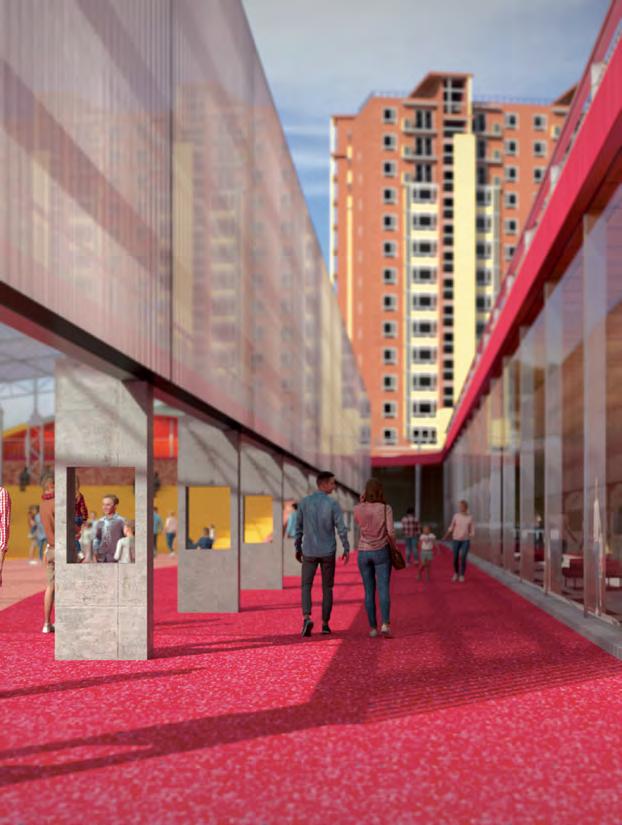
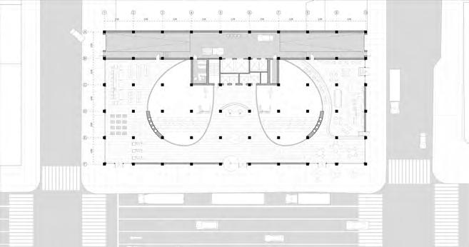
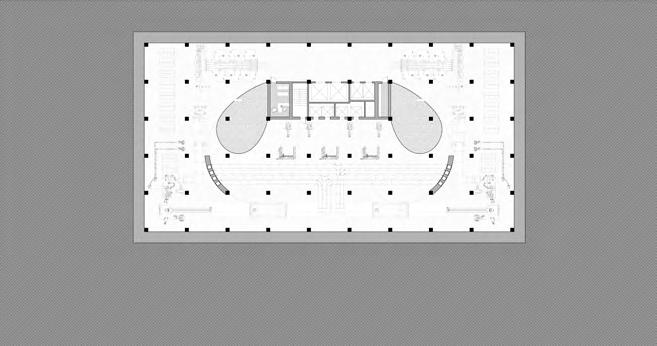
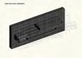
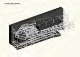
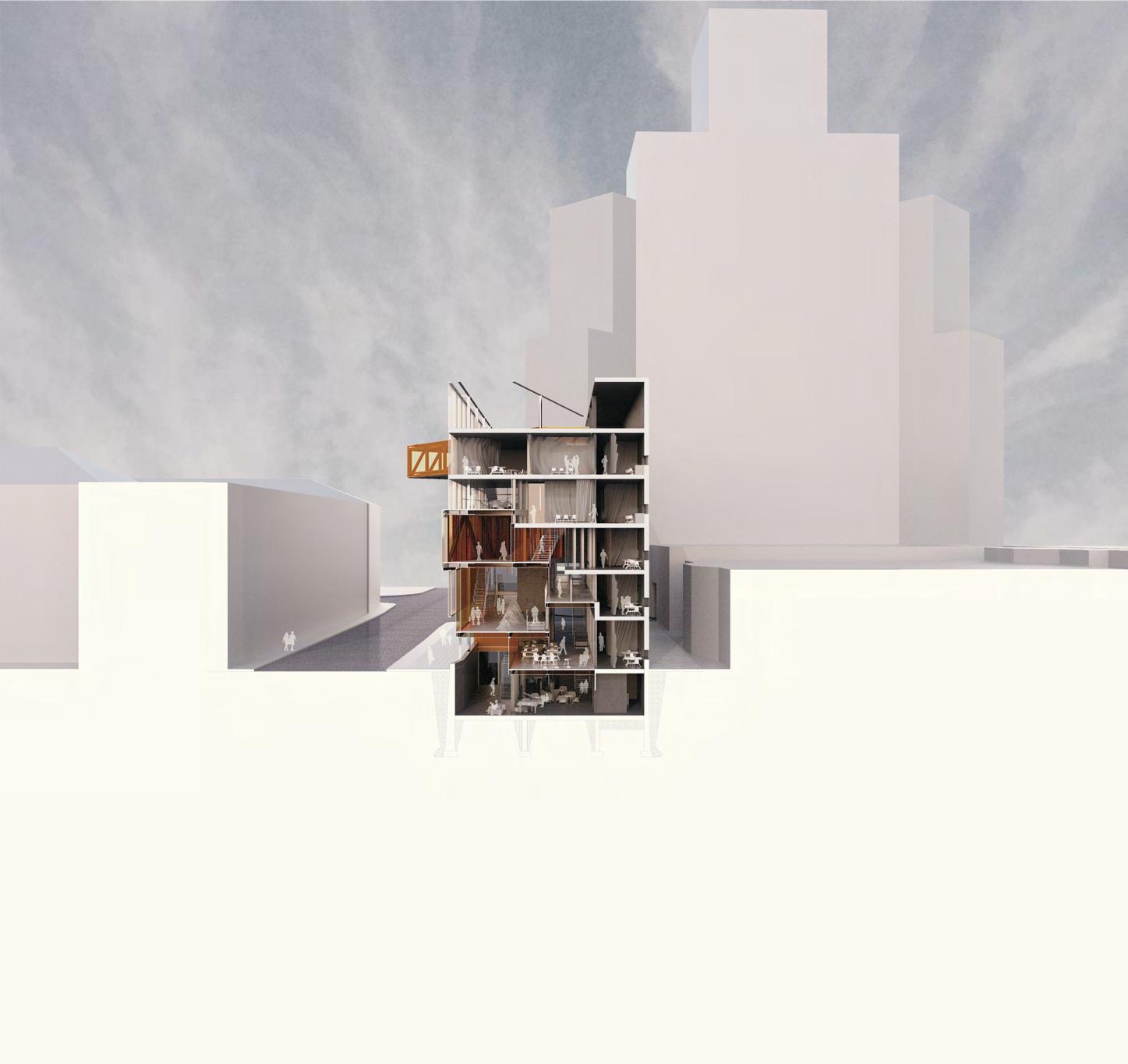
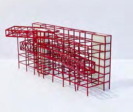
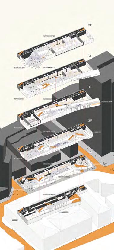
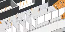
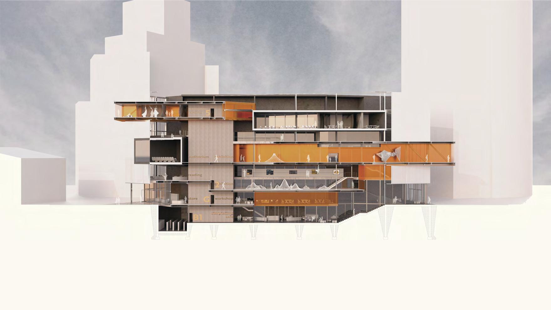
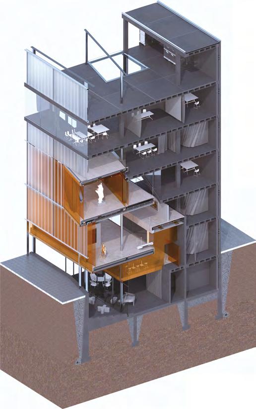
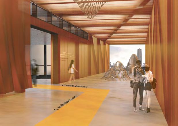
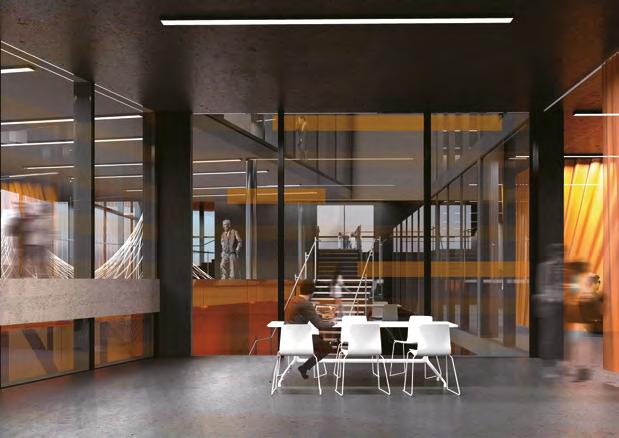
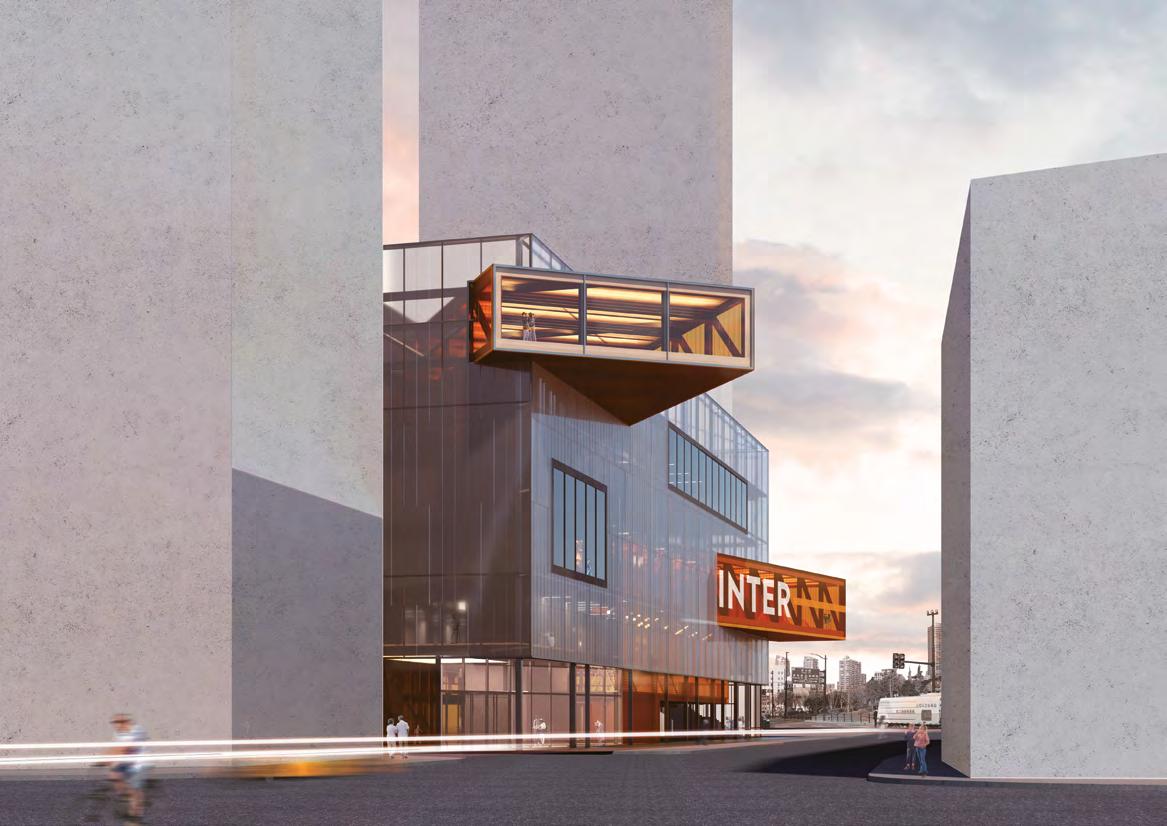
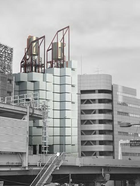
As Shanghai’s economic and cultural centre has shifted southward with the introduction of bills promoting the development of Pudong in the past two decades following the opening up policy in China, it became clear that Hongkou is an area waiting to be reactivated through public programs. INTER- will be a cultural institution devoted to hosting communal gathering, cultural research and cultural exhibition, responding to the key constituencies, the seniors, local residents, tourists, researchers, and young professionals. INTER-’s program envisions a dynamic mix of formal and informal programs. On one hand, the formal programs serves as the backbones, providing a platform for cultural preservation, and research, and collaborative working; on the other hand, the informal programs serve as a public interface where the public are encouraged to engage in improvised exhibitions, storytelling, and reading. The informal and formal are imagined as two pieces in friction with each another, misaligned, and spatially interlocked, allowing visual, auditory interchange and unexpected encounters between the different groups. Within the project, heavy cast-in-place concrete is used for the back, while light steel structure is pushed to the front. Nestled together, the two structural systems hint at duality of the solidity of the research spaces, and the impromptu, light-filled nature of the exhibition spaces.
04 INTER-
Site Analysis
The site of the project is in Hongkou District, Shanghai. Hongkou District used to be the most popular and active place in the city of Shanghai. However, as the economic centre shifted to the east of Shanghai, Hongkou lost in the developing process of Shanghai.
The population of Hongkou dropped dramatically in the last decade. Also, the aging of the population in Hongkou has become a significant problem. Unlike the old Hongkou, as an active and popular district, low-quality housing and small business offices take over the majority of land use in Hongkou.
2018 1990 2000 2010 147 M 48.7 B 241 B 545 B Shanghai GDP (in USD) Secondary Industry tertiary Industry Primary Industry 2004 2006 2008 2010 2012 2014 2016 2018 Pudong District Hongkou District 6483 8257 4795 12297 4181 14956 7173 1487 1912 4046 739 2297 6206 547 4280 32 Housing Expropriation (# of Households) Age Break down 0-1718-3434-59>60 2004 2006 2008 2010 2012 2014 2016 2018 2004 2006 2008 2010 2012 2014 2016 2018 Hongkou Pudong Pudong District 2018 2016 2014 2012 2010 2008 2006 23.48 23.48 23.48 23.48 23.48 23.48 2004 23.48 522.75 Size of District (Sqkm) Hongkou District 532.75 532.75 1210.41 1210.41 1210.41 1210.41 1210.41 36299 4585 33944 4545 34314 4504 35698 4275 36269 5738 4170 3521 33267 33518 3461 33599 Population Density (person/sqkm) 2004 2006 2008 2010 2012 2014 2016 2018 Pudong District Hongkou District 23.48 HONGKOU VS. PUDONG 2018 1990 2000 2010 147 M 48.7 B 241 B 545 B Shanghai GDP (in USD) Secondary Industry tertiary Industry Primary Industry Pudong District 2018 2016 2014 2012 2010 2008 2006 23.48 23.48 23.48 23.48 23.48 23.48 2004 23.48 522.75 Size of District (Sqkm) Hongkou District 532.75 532.75 1210.41 1210.41 1210.41 1210.41 1210.41 23.48 2018 1990 2000 2010 147 M 48.7 B 241 B 545 B Shanghai GDP (in USD) Secondary Industry tertiary Industry Primary Industry Pudong District 2018 2016 2014 2012 2010 2008 2006 23.48 23.48 23.48 23.48 23.48 23.48 2004 23.48 522.75 Size of District (Sqkm) Hongkou District 532.75 532.75 1210.41 1210.41 1210.41 1210.41 1210.41 23.48
according exhibiconnecpublic to research-
Design Process
The project site has a strong north-south directivity, which we want to take advantage of this directivity. This directivity provides an interesting physical connection between Hongkou and the Bund, one of the most active and fancy places in Shanghai, and a visual connection with the most iconic landmark in Shanghai, Oriental Pearl Tower.
The concep t of this project is as a connecting node and interlock not only the people of
and modern Shanghai but also the culture together as a starting point of reactivating the Hongkou District. Therefore, in stage 4, we were testing out the possibility of circulation in the front space. Our intention of designing circulation was making the circulation wraps around the program, and to create an interior interlock between different programs.
Site Formal VS. Informal Misalignment Programmtic Interlock Sunken Entry
The building is situated in an urban context, and a convergence point between the suzhou and huangpu river. Therefore, the site presents a unique opportunity to deal with traffic on 2 fronts, one facing the riverfront, and the other open to a public plaza.
In terms of massing strategy, the proposal imagines two program groups: formal programs which include cultural research and archives; and informal programs which include flexible exhibition and public gathering spaces. The formal programs and back of house are pushed to the back, while the informal programs displays the vibrant activities to the urban front.
The two programs are intentionally misaligned according to the different dimensional requirements for the exhibition spaces. This generates visual, auditory and connections between the front and the back, allowing public to come into unexpectedly visual contact with the researching and archiving spaces.
The massing is maniputed so that the formal spaces interlock with the informal spaces, generating further friction between the two distinct programme groups. The informal exhibition spaces are extruded, and rotated to frame views of both the riverfront and urban plaza.
The ground is caved, creating a public void that attracts passersby with the internal public programs. It also serves as a way to introduce the public down into the
The building is enclosed with translucent materials, creating a sense of furtive transparency. That people have a hazy understanding of the internal complexity of the building. But once they enter, the building opens up to show its intricacies through the interlocking system between the two types of programmes.
Programmtic Interlock Sunken Entry Enclosure
The massing is maniputed so that the formal spaces interlock with the informal spaces, generating further friction between the two distinct programme groups. The informal exhibition spaces are extruded, and rotated to frame views of both the riverfront and urban plaza.
The ground is caved, creating a public void that attracts passersby with the internal public programs. It also serves as a way to introduce
PROCESS DIAGRAM
the public down into the building.
The building is enclosed with translucent materials, creating a sense of furtive transparency. That people have a hazy understanding of the internal complexity of the building. But once they enter, the building opens up to show its intricacies through the interlocking system between the two types of programmes.
1 4 2 3
Hongkou
Programs
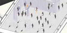
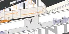
The project has an interlock of two major programs: Formal and Informal spaces. The formal space contains WeWork sharing office room, archive, and the lab of the historical study of Hongkou. The informal area tends to be the most active space in this building. It contains exhibiting space, cafe, and storytelling space for seniors living in Hongkou district sharing their adventure with young people.
To visually emphasize the concept of formal and informal, the material and structure used in those spaces are different. Formal space uses a solid concrete structure and interlock with informal’s light metal structure to illustrate the difference between programs and the activeness.
FORMAL Lecturing Archive Gallery A Large Installations INFORMAL Gallery B Medium Scale Sculptures & Digital Media DIMENSIONAL TAXONOMY Visual Acess Public Circulation Natural Light Acess Auditory Acess 12500mm 4000 mm 1400 mm 1350 mm 4300 mm 1600 mm 8400 mm 2400 mm 3600 mm 25000 mm 1300 mm 2000 mm 25000 mm 2900 mm 7800 mm 2200 mm 6200 mm 6500 mm 5200 mm 10750mm 4300 mm 2600 mm 650 mm 750 mm GALLERY GALLERY GALLERY Arrival ARCHIVE Story Telling WEWORK STUDIO AUDITORIUM FUNCTIONAL SECTION DIAGRAM Shop + Cafe READING READING LECTURE READING READING WEWORK STUDIO WEWORK + STUDIO WEWORK + STUDIO ResearchResearch INFORMAL VS. FORMAL PROGRAMME PUBLIC ENTRY RESEARCH VS. EXHIBIT PUBLIC PUBLIC PUBLIC PUBLIC -5500 Archive -3950 Basement Level/ Cafe 3300 2nd Level/ Exhibition 5400 3rd Level/ Reading 9600 4th Level/ Auditorium/ Exhibition 14500 5th Level/ Exhibition 15250 5th Level/ Story-Telling 17400 6th Level/ Wework Space 21600 Roof Level 23700 Roof Level 0 Ground Level 0 a a’ 5 10 20m Section aa’ 1:50 D C B A 4500 4500 8000
REST AREA EXHIBITIONEXHIBITION EXHIBITION WORKSHOP STORY-TELLING/CAFE WEWORK WEWORK OFFICE OFFICE OFFICE MACHANICAL
A” 2” 3” 4” 5” 6” C” 6735 6735 4700 4500 4700 3720 1400 12165 21.6 A’ 3’ 4’ 10’ 11’ 12’ 5200 5200 5200 5200 5200 5200 5000 5000 860 5000 4 B A b’ b Exhibition Wework Space Meeting Room Electrical Control Room Restroom 5th Floor Plan 1:150 9.6 3’ 4’ 10’ 11’ 5200 5200 5200 5200 5200 5200 720 5000 5000 860 5000 Reading Room Exhibition Gallery Electrical Control Room Restroom Research Office D C B b’ b 4th Floor Plan 1:150 B’ A’ 3’ 4’ 7’ 10’ 8’ 12’ 5200 5200 5200 5200 5200 5200 5000 5000 860 5000 1. Reading Room 2. Exhibition 3. Gallery 4. Electrical Control Room 5. Restroom 6. Research Office 7. Meeting Room 3rd Floor Plan 1:150 b’ b a’ Ground Floor Plan 1:150 0 5 10 20m 1. Lobby 2. Shop 3. Electrical Control Room 4. Workshop 5. Research Office 6. Restroom 7. Meeting Room 0 0 0 2 3 4 5 6 8 10000 10000 10000 10000 10000 10000 10000 D C B A 4500 4500 8000 a b’ b a’ 1. 2. 3. 4. 5. 6. 7. 1. Archive 2. Story-Telling Space 3. Electrical Control Room 4. Mechanical Room 5. Men’s Restroom 6. Women’s Restroom 7. Lobby 8. Bleachers 9. Cafe b’ b a’ Basement Floor Plan 1:150
WEWORK STORY-TELLINGCORE & READING REST AREA EXHIBITION EXHIBITION WORKSHOP STORY-TELLING/CAFE ARCHIVE
REST AREA READING LOBBY/STORE ENTRANCE AUDITORIUM
-5500 Archive -3950 Basement Level/ Cafe 3300 2nd Level/ Exhibition 5400 3rd Level/ Reading 9600 4th Level/ Auditorium/ Exhibition 14500 5th Level/ Exhibition 15250 5th Level/ Story-Telling 17400 6th Level/ WeWork Space 20400 6th Level/ Exhibition 21600 Roof Level 23700 Roof Level 0 Ground Level b b’ 0 5 10 20m Section bb’ 1:50 5200 5200 1‘ 2’ 3‘ 4500 4700 2” 1“ 3 10000 10000 10000 10000 10000 10000 10000 5200 5200 5200 5200 5000 5000 5000 12165 1400 3720 4700 8 7 6 5 4 4’ 5‘ 7’ 10’ 11‘ 12’ 8‘ 3“4” 5“6” 7” 2 1
D-01 D-01 D-02 D-03 D-02 D-03 40mm white polycarbonate Sloped metal support for water drip Aluminum strip to cap frame Rectangle stainless steel manhole cover Waterproofing layer Roof concrete finish Rigid insulation 50mm thickness hollow frame Neil structure to conncet frame and concrete slab Window frame for two layers of double glazing glass Concrete panel ceiling 18mm orange polycarbonate 150mm purlins polycarbonate support Concrete pavers with 1% slope Insulated protection borad (metal type) Concrete floor finish Rubber strip Rubber flashing waterproofing Drilled neil for polycarbonate frame Interior polycarbonate support Fire-proofed layer 30mm thickness hollow polycarbonate frame Frame for two double glazing glass Double glazing glass 20mm concreete panel finish HVAC duct Interior polycarbonate support 18mm orange polycarbonate Drilling metal joist “C” shape beam Concrete floor finish Prefabricated waffel concrete floor Thermal insulation Wooden bed for supporting neil structure 10 14 16 18 19 20 22 23 24 25 26 27 29 30 32 34 35 36 37 38 37 39 40 42 43 44 46 47 48 49 52 53 54 56 55 1. Aluminum strip to cap parapet 2. Aluminum water drip 3. Aluminum hook 4. Wooden block 5. Parapet finish 6. Concrete parapet 7. Waterproofing 8. Insulation 9. Porous concrete leveler 10. Aluminum roof underlayer 11. Rigid insulation 12. Porous concrete finish 13. Waterproofing layer under roof finish 14. Prefabricated waffel concrete floor 15. Concrete panel dropped ceiling 16. Fire water tank 17. Concrete pavers roof finish with 1% slope 18. Waterproofed seal 19. Municipal water pipe 20. Fire main 21. Sewage pipe 22. HAY office table collection 23. HAY office chair collection 24. Silk curtain 25. Curtain screen 26. Sprinkler pipe (connect to fire main and water tank) 27. Electric wire pipe 28. HVAC Wind duct (return) 29. Air cavity to minimize leaking 30. Thermal insulation 31. Wall waterproof layer 32. Concrete durable wall covering 33. HVAC Wind duct (support) 34. Reinforced concrete column 35. Aluminum window frame 36. Aluminum window mullion 37. Double glazed window for formal program 38. Customized steel handrail 39. Temperate display wall 40. Wooden frame art work 41. “C” shape beam nail connects to prefabricated concrete structure 42. 400mm “C” shape beam 43. Hanging parts of visible frame keel 44. Electric pipe for informal program 45. Sprinkler pipe for informal program 46. 38 main keel 47. Hanging pole 48. Hanging parts of 38 main keel 49. Supporting structure for keel 51. 300mm x 300mm window frame 52. Exterior ground concrete finish 53. Gravel layer 54. Gravel bed 55. Rigid insulation for base 56. Soil 57. Thermal insulation and separating layer 58. Concrete curtain wall basement 59. Drainage pipe 60.Φ250mm Polished rectangle steel column 61. Waterproofed aluminum roof glass frame 62. Triple glazed roof glass 63. 300mm x 300mm Polished rectangle steel column 64. Roof frame for polycarbonate 65. 150mm purlins polycarbonate support 66. Aluminum strip to cap polycarbonate frame 67. Rectangle stainless steel manhole cover 68. 50mm thickness hollow embedded Insulated polycarbonate frame 69. Aluminum frame for two layers of double-glazed glass 70. Two layers of double-glazed glass 71. Aluminum mullion for two layers of double-glazed glass 72. 30mm thickness hollow embedded Insulated polycarbonate frame 73. Concrete floor finish 74. Pre-casted concrete on metal deck 75. Roof concrete pavers with 1% slope 76. Metal hook for supporting polycarbonate panel 77. Roof frame for colored polycarbonate 78. Concrete finish wrap 79. 400mm “I” shape beam 80. 100mm x 100mm interior polycarbonate frame 81. Protection board 82. 400mm “I” shape truss 83. Metal deck 84. Drilled neil for polycarbonate frame 85. Metal hook to support ceiling polycarbonate 86. Metal hook to support exterior polycarbonate 87. 40mm white polycarbonate 88. 18mm orange polycarbonate 89. 40mm orange polycarbonate 90. Steel staircase 91. HAY café table collection 92. HAY comfort chair collection 93. YAMAHA piano design edition 94. Embedded exterior window frame 95. Waterproofed finish layer 96. Front curtain wall as street front bench 97. Concrete panel for street side walk 60 61 62 63 64 65 66 67 10 10 12 11 67 68 69 70 71 73 74 75 76 30 78 79 80 28 27 26 81 82 33 83 79 84 4 85 86 87 88 89 91 92 93 94 96 58 59 D-01 D-01 D-02 D-03 D-02 D-03 40mm white polycarbonate Sloped metal support for water drip Aluminum strip cap frame Rectangle stainless steel manhole cover Roof concrete finish Waterproofing layer Roof concrete finish Rigid insulation 50mm thickness hollow frame Neil structure to conncet frame and Window frame for two layers of double glazing glass Concrete panel ceiling 18mm orange polycarbonate 150mm purlins polycarbonate support Concrete pavers with 1% slope Insulated protection borad (metal type) Concrete floor finish Rubber strip Rubber flashing waterproofing Drilled neil for polycarbonate frame Interior polycarbonate support Fire-proofed layer 30mm thickness hollow polycarbonate frame Frame for two double glazing glass Double glazing glass 20mm concreete panel finish Interior polycarbonate support 18mm orange polycarbonate Drilling metal joist “C” shape beam Concrete floor finish Thermal insulation Wooden bed for supporting neil structure 10 22 23 24 25 28 29 30 34 35 36 37 38 39 40 35 44 45 46 47 50 52 53 1. Aluminum strip to cap parapet 2. Aluminum water drip 3. Aluminum hook 4. Wooden block 5. Parapet finish 6. Concrete parapet 7. Waterproofing 8. Insulation 9. Porous concrete leveler 10. Aluminum roof underlayer 11. Rigid insulation 12. Porous concrete finish 13. Waterproofing layer under roof finish 14. Prefabricated waffel concrete floor 15. Concrete panel dropped ceiling 16. Fire water tank 17. Concrete pavers roof finish with 1% slope 18. Waterproofed seal 19. Municipal water pipe 20. Fire main 21. Sewage pipe 22. HAY office table collection 23. HAY office chair collection 24. Silk curtain 25. Curtain screen 26. Sprinkler pipe (connect to fire main and water tank) 27. Electric wire pipe 28. HVAC Wind duct (return) 29. Air cavity to minimize leaking 30. Thermal insulation 31. Wall waterproof layer 32. Concrete durable wall covering 33. HVAC Wind duct (support) 34. Reinforced concrete column 35. Aluminum window frame 36. Aluminum window mullion 37. Double glazed window for formal program 38. Customized steel handrail 39. Temperate display wall 40. Wooden frame art work 41. “C” shape beam nail connects to prefabricated concrete structure 42. 400mm “C” shape beam 43. Hanging parts of visible frame keel 44. Electric pipe for informal program 45. Sprinkler pipe for informal program 46. 38 main keel 47. Hanging pole 48. Hanging parts of 38 main keel 49. Supporting structure for keel 50. 18mm Colored polycarbonate dropped ceiling 51. 300mm x 300mm window frame 52. Exterior ground concrete finish 53. Gravel layer 54. Gravel bed 55. Rigid insulation for base 56. Soil 57. Thermal insulation and separating layer 58. Concrete curtain wall basement 59. Drainage pipe 60.Φ250mm Polished rectangle steel column 61. Waterproofed aluminum roof glass frame 62. Triple glazed roof glass 63. 300mm x 300mm Polished rectangle steel column 64. Roof frame for polycarbonate 65. 150mm purlins polycarbonate support 66. Aluminum strip to cap polycarbonate frame 67. Rectangle stainless steel manhole cover 68. 50mm thickness hollow embedded Insulated polycarbonate frame 69. Aluminum frame for two layers of double-glazed glass 70. Two layers of double-glazed glass 71. Aluminum mullion for two layers of double-glazed glass 72. 30mm thickness hollow embedded Insulated polycarbonate frame 73. Concrete floor finish 74. Pre-casted concrete on metal deck 75. Roof concrete pavers with 1% slope 76. Metal hook for supporting polycarbonate panel 77. Roof frame for colored polycarbonate 78. Concrete finish wrap 79. 400mm “I” shape beam 80. 100mm 100mm interior polycarbonate frame 81. Protection board 82. 400mm “I” shape truss 83. Metal deck 84. Drilled neil for polycarbonate frame 85. Metal hook to support ceiling polycarbonate 86. Metal hook to support exterior polycarbonate 87. 40mm white polycarbonate 88. 18mm orange polycarbonate 89. 40mm orange polycarbonate 90.Steel staircase 91. HAY café table collection 92. HAY comfort chair collection 93. YAMAHA piano design edition 94. Embedded exterior window frame 95. Waterproofed finish layer 96. Front curtain wall as street front bench 97. Concrete panel for street side walk 60 61 64 65 66 10 69 70 71 73 74 75 76 78 79 80 28 81 82 33 83 85 77 86 89 90 91 92 95 96 58 57 SUMMER 12:00 SPRING 12:00 FALL 12:00 WINTER 12:00 Passive Ventailation Natrul Air Through Operable Window WINTER 12:00 as example Deffusing Light through Polycarbonate
Lower Extrusion Render WeWork Space Render
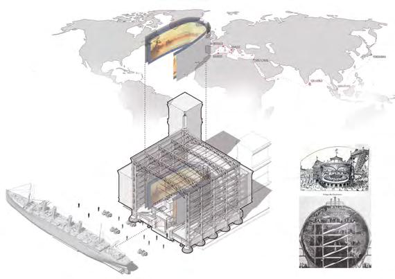
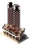
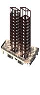
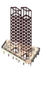
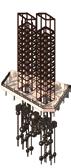
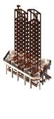
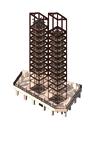
05 NAKAGIN TOWER: RECONTEXTUALIZATION IN MEDIA ERA
| Design & Research Work | Co-work with Yixuan Li
Studio Work | Fall 2020 | Syracuse School of Architecture Beijing

Instructor: Zigeng Wang
"The printed book will destroy the building"
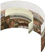
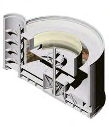
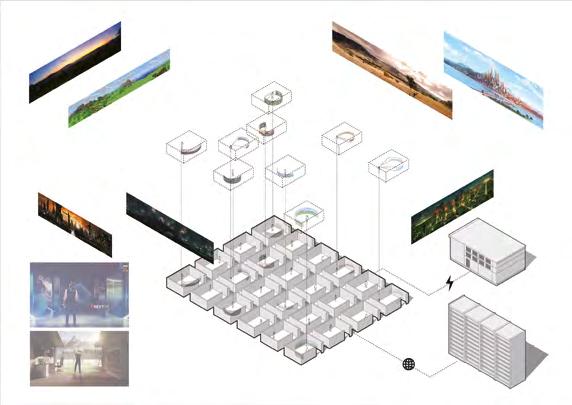
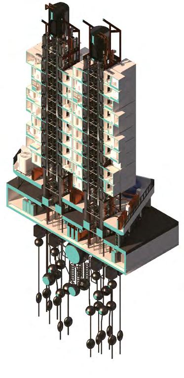
Tracing back in 1900s, when media firstly in the forms of machines like TVs, radios, and movies, Nakagin Capsule Tower was an avant-garde design to claim a possible future. Individualization of society, intrusion of media, and conversation within machines are the hints that KUROKAWA unintentionally claimed. Destroying it is the death of an old manifesto, probably the most insulting way. What is the domestic space today? We seek for a recontextualization, a remanifesto for media era, aiming to refill Nakagin tower within a new essence: A core with insane infrastructure, a podium with numerous machines, and a basement with data servers. The metabolism that we define for nowadays is to feed human with fragile fantasy and growing infrastructure. The media era that we claim is an individualized bubble dream under the swarm of machines.
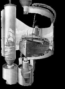
"ceci tuera cela" Victor Hugo,Notre Dame De Paris,Yates, 124.The Research of Panorama
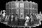
Throughout the research of the media of panorama, we found out the form of this media has a very close relationship with spaces and social structure. From the very beginning of private long-drawing exhibited in the Capitoline Museum, which only exhibited for upper-class people; to Robert Barker created the term “panorama“ and his rotunda, to blur the idea of class in the building, and to praise the panorama drawing; and Hugo’s ship to simulate the reality from the
1900
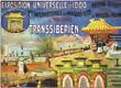
Trans-Siberian Railway Panorama, Pavel Yakovlevich Pyasetsky
1787
The word “panorama” – from the Greek pan (all) and horama (view) – was first used by Robert Barker, an Irish-born painter living in Edinburgh.
1647
Long View of London from Bankside, a panorama of London by Wenceslaus Hollar, 1647, notable for being rendered all from one viewpoint.
The Railway Panorama was commissioned by Compagnie International des Wagons Lits, and shown in the Siberian section of the Exposition’s Russian pavilion. It recreated the most interesting stages of a journey from Moscow to Beijing on the Trans-Siberian Railway.
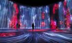
panorama. We assumed that the form of panorama nowadays or in the future is Virtual Reality. With the development of technology, a more realistic virtual world will be present on our sight, and how will people experience this new imaginary world? What is the new architectural form of this kind of panorama?


1900
The Mareorama, Hugo d’Alesi
To project the illusion of being on a ship deck cruising to Mediterranean, the Riviera, Venice, Naples etc. Which had multiple inputs (audio, visual, sound, smell, sensation: breeze) to create a multisensorial experience.

Peasants’ War Panorama

It is a monumental painting by the East German painter Werner Tübke, executed from 1976 to 1987. It depicts a circular panorama of the Battle of Frankenhausen, fought on 15 May 1525 during the German Peasants’ War. The painting has more than 3000 characters.
2001 - present
Virtual Reality (VR)
is a simulated experience that can be similar to or completely different from the real world. Applications of virtual reality can include entertainment (i.e. video games) and educational purposes (i.e. medical or military training).


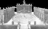
The Capitoline Museums began in 1471 with a donation of classical sculpture to the city of Rome by the Papacy. The first official gallery for nobles to see artwork collections.
1793

Barker moved his panoramas to the first purpose-built panorama building in the world, in Leicester Square, and made a fortune.
16 Leicester Square 1789
1900
The Kaiserpanorama Show a series stereoscopic slides of exotic places. A showing lasted around half an

A painter of advertising posters, and was a combination of moving panoramic paintings and a large motion platform. It is regarded as one of the last major developments in the technology of panoramas, shortly before the medium became obsolete.
1976
Early Bourgeois Revolution in Germany
This location was chosen for the construction of the Panorama Museum because of the historic event of the last decisive battle in the Peasants’ War in 1525 which was fought on Battle Hill.
2001
teamLab
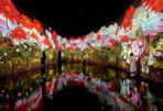
Is an international art collective, an interdisciplinary group of various specialists such as artists, programmers, engineers, CG animators, mathematicians and architects whose collaborative practice seeks to navigate the confluence of art, science, technology, and the natural world.
 Frédéric Hugo d’Alesi (1849-1906)
hour.
Disegno di Jakob Ignaz Hittorff per il Panorama Rotunda a Parigi 1838
Robert Barker (1739 – 8 April 1806)
Frédéric Hugo d’Alesi (1849-1906)
hour.
Disegno di Jakob Ignaz Hittorff per il Panorama Rotunda a Parigi 1838
Robert Barker (1739 – 8 April 1806)
1471
The Form of Panorama Space

“Landscape” Control
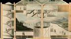
An exquisite design of the interior landscape of this Rotunda made the control of human gesture and light possible. The early typology of making illusions are achieved through this built environment including skylight and height difference.
Worldwide Conquer
Panorama was initially created for exhibiting some scenes of wars to celebrate the greatness of their outward expansion. A panorama was also employed as a media to expanding human’s horizon by regenerating the scenes of various events.
Five Senses of Human
Vision
Auditory Sense
Smell Gustation Tectil Sense
Industrial Revolution
Technological Support:
The 2nd Industrial Revolution application of mechanical system. In the worldwide area, as result, traveling based on machines has been prevailing.
“CLOU” Fever
The so-called clou fever encourages more and more chase comprehensive illusion including “five feelings”., which sets a background for the advent of “Mareorama”.
Five Senses of Human
The
Other Media Shock Swayed by other types of media, such as films and televisions, panorama becomes more like a piece of artwork to memorize historical events. And the space of it, becomes public space for exhibition. Lugou Bridge Incident Capture Jin Zhou Electrical Light
continuous advancement of electricity after WWII brings panorama a new typology: artificial light, which therefore simplifies indoor space to a great extent. Virtual Reality
The
revolutionary
immersive
visitors,
size
panorama
space. The spread of electricity and Internet make all the resources that depicts scenes possible around the world. People can even travel the world without going to specific space. Vision Smell Gustation Tectil Sense Auditory Sense
opportunity that finally brings panorama a new face was the advent of VR, which greatly enhance the
experience of
also shrinking the
of a
room
2015
Modern Exhibition
With the advancement of other
media such as movies, and TV, panorama gradually become common places for individuals to
commemorate historical events.
The requirement of space, due to
the advent of modern electrical system, is humble.
1950
VR VR makes the “panorama” evolving again,
which boosts virtual experience to an un-
precedented level. Also, this portable equip-
ment enables panorama to be an individual
technology in each and every housing units.
Leicester Rotunda
Designed by Robert Baker, this Rotun-
da-like structure was specifically built to
exhibit the panorama drawing. For better
1900
1785
Mareorama A masterpiece combining mechanical sys-
tem to realize immersible environment for
panorama. It is not designed only to opti-
mize visual experience, but also to improve
“feelings” from hearing, eating, smelling
and touching.
controlling the light, this rotunda has a clear
decision between “dark” and “bright” to
create contrast for visitors.
Art Gallery Early architecture for exhibiting paintings. An art gallery usually
does not possess a strict control
for light and circulation, and it
specifically serves for a certain group of people
1500
Nakagin Capsule Tower illustrated a new lifestyle with a combination of media, Architecture, and isolation. As we re-manifesto for our future of media era, we claim a new lifestyle and domestic space for humans, specifically for those called “Shachiku, “ meaning that an employee who is entirely subservient to their company, never complaining about overwork or any other issues. After all of the social activities during the daytime, they were so exhausted from contact with people. They want to be “self-closing “ and diving into the world of media, to be another version of themselves.
DAILY TIMELINE OF “SHACHIKU“
“SELF-CLOSING”
REBORN NAKAGIN TOWER ROOF TOP FOR MACHINE STEEL FRAME AND SYSTEMS GEOTHERMAL AND DATA VERTICAL CIRCULATION PODIUM FOR MACHINES CELLS ROOF TOP FOR PUBLIC AREA CONCRETE CORE SPIRAL STAIR-CIRCULATION CELLS Geothermal Core Geothermal Supply Infrastructure Core Data Center Electricity Water Parcel Sta�on Podium (Machine Ocuppied) Air Condi�on Terminal End 9 2322212019 24 18 876 1011 123456 121314151617 SOCIALIZATION WORK WORK RECREATION
SLEEPING EXERCISE EXERCISE EXERCISE EATING EATING EATING
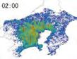
• People flow reconstruction in a 3D time series


Working Status of Tokyo Employees
• Progressively rationalized working hours
Overtime work
An employee who is completely subservient to their company, never complaining about overwork or any other issues; a wage slave
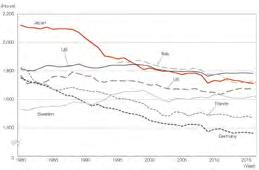
There is a trend towards shorter working hours, but working hours are still relatively long compared to other developed economies
• Extremely long working hours
• Reason for overtime work
Heavy workload
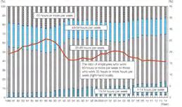
Sudden and unexpected tasks
Since 1 987, Japanese Labor Standards has set the legal working hours at 40 hours per week, but as of 2014, a large percentage of employees still work more than 40 hours per week, and a large percentage even work 60 or more hours.
• Work Types and Work Hours
Looking at the breakdown by industry, the industry with the highest percentage of employees working 60 hours or more per week was transport and postal services (17.7%), followed by education (12.6%), and construction (10.7%) in 2017.

The number of people in each 1-km2 mesh

Non-scheduled workinag hours
Shortage of personnel Tight deadline

Properly complete work
Workload fluctuates sharply
Co-workers working overtime
Ineffective guidance from supervisors
Inadequate skills
Managing subordinates
Earn overtime pay
Work content changes frequently
Other
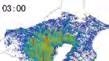
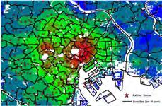
The image illustrates a 3D time-series representation with a height axis that indicated the number of people aggregated according to a 1-km2 mesh. This shows a drastic change between daytime and night time (for example, between 8:00 to 9:00, 18:00 to 20:00), especially in central Tokyo (such as the Ginza area).


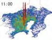
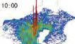
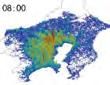
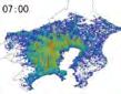


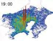
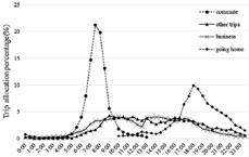
• Trip flow visualization
Trips visualized in a time series representation. Each line represents a trip, and each color represents a movement status (green: train, orange: vehicle).Brightness shows the congestion degree.
Stations in the downtown area (e.g. Ginza area) are popular for commuters. For commuters with different travel purposes, the time of departure and the morning and evening rush hours are displayed in the chart on the left
Source: Kashiyama, T., Pang, Y., & Sekimoto, Y. (2017). Open PFLOW: Creation and evaluation of an open dataset for typical people mass movement in urban areas. Transportation research part C: emerging technologies, 85, 249-267.
Source : OECD Data, “Hours worked,” https://data.oecd.org/ emp/hours-worked.htm. Quoted in Japan Institute for Labour Policy and Trainin (JILPT), Databook of International Labour Statistics 2018 (Tokyo: JILPT, 2018), figure 6-1, 203. Source: Prepared by Office of Counsellor for Labour Policy Planning of MHLW, based on the MIC’s Labour Force Survey (Basic Tabulation). Source: Ministry of Internal Affairs and Communications Labour Force Survey. Quoted in the 2018 White Paper on Measures to Prevent of Karōshi (Death Caused by Overwork), etc.
63.9% 31.2% 30.2% 25.5% 25.1% 24.1% 17.3% 9.8% 8.5% 8.4% 7.0% 3.9% 2.9% 3.2%
00:00 05:00 10:00 15:00 20:00 01:00 06:00 11:00 16:00 21:00 00:00 07:00 12:00 17:00 22:00 02:00 08:00 13:00 18:00 23:00 03:00 09:00 14:00 19:00
1-25 401-500 351-400 301-350 3001251-300 2001-3000 201-250 1501-2000 150-200 1001-1500 101-150 801-1000 76-100 701-800 51-75 601-700 26-50 501-600 06:00 15:00 09:00 18:00 12:00 22:00 Trip allocation percentage (%) Commute Other
Business Go home Shachiku
trips
Redesign the Core
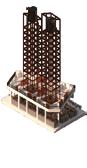
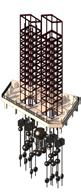
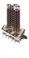

The old core of the tower is for circulation; however, we want the new core contains all the infrastructure that supplies a person’s daily needs without going out of the capsule. The new core remains the same structure as the old core, but no surface on the structure. People can see different pipes and ducts in the core that supply each capsule. which have water pipes, air ducts, electricity cables, items, food delivery ducts, geothermal pipes, and a basement with data servers to supply the media in capsules. In this fantasy, the new lifestyle of humans is under the swarm of infrastructure.

STRUCTURE CIRCULATION WATER AIR-CONDITION ELECTRICITY ITEMS&FOOD GEOTHERMAL DATA CENTER
Geothermal Core Geothermal Supply
Infrastructure Core
Data Center
Electricity
Water Parcel Sta�on
Podium (Machine Ocuppied)
Terminal End
Air Condi�on
Redesign the Capsules
We break the old capsule into different typologies: bathroom, closet, kitchen, seat, bed, table (with TV and radio in it), bedside table, and window. By keeping the original shape and size of the capsules, we get rid of the seat, window, and bedside table and add an express box to connect the supply ducts, a refrigerator and microwave, and a panorama screen for VR and media world experience. For different combination studies, we also suggest that maybe there are only cables for media and pipes for human needs in one capsule, which people can immerse in the world of imagination.

OLD CAPSULE NEW CAPSULE BATHROOM BATHROOM CLOSET CLOSET KITCHEN BEDSIDE TABLE TABLE
MICROWAVE EXPRESS BOX TABLE BED BED WINDOW
FRIDGE&
SEAT
PANORAMA SCREEN
 EXPRESS SERVICE
ELECTRICITY SERVICE
AIR CONDITIONER
WATER TANK
EXPRESS SERVICE
ELECTRICITY SERVICE
AIR CONDITIONER
WATER TANK

Terminal
Industrialized Podium
Parcel Sta�on Pla�orm
Data Center Basement
06 LIFE OF ART

| Design Work | Individual Work Studio Work | Fall 2018 | Syracuse School of Architecture
Instructor: Valeria Rachel Herrera
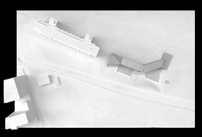
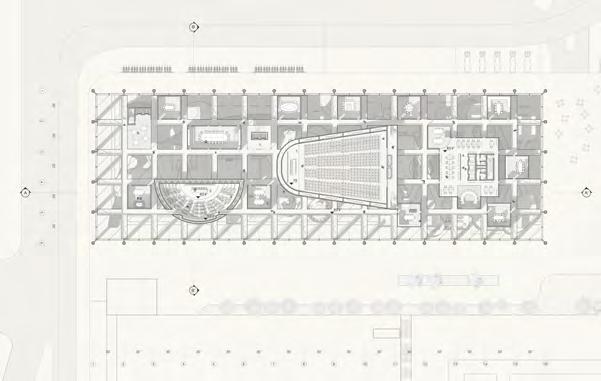
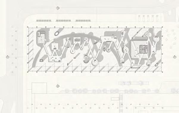
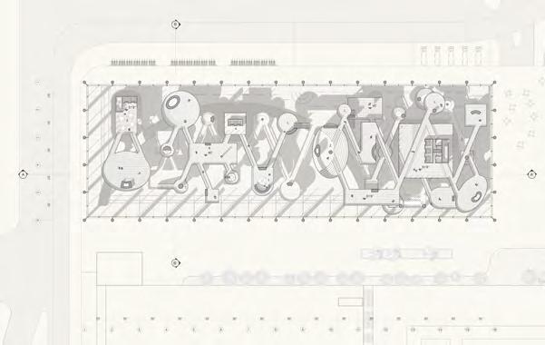
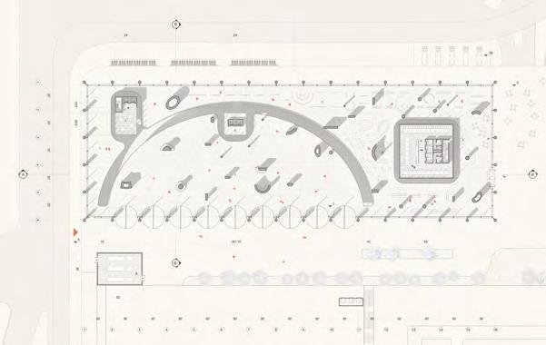
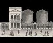
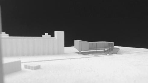
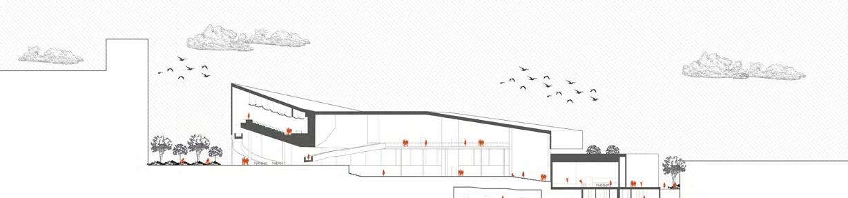
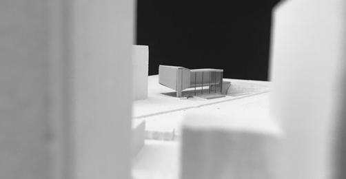
The project is to design an art centre for artists to produce and to exhibit their works. The site is located at the Silo City in Buffalo, which is an abundant factory plaza and now use for some concert events. The concept of this project is “life of art,” which from the basement artist’ s studio to the ground floor exhibition space, then to the upper floor performing space. Also the hight of roof of the project is sloping down from the existing silo building to the underground studios. As Silo City was the most active place in Buffalo back to early half of 1800s, another purpose of this building is reactive to the site and to create a common plaza for the artist, visitors, and local people. Also the from of sloping roof and general elevated programs are tending to praise the work of artists.
0 km 3 km 6 km Silo City Downtown Lake Erie Artist’ s Studio Exhibition Space Performing Space Art Plaza Buffalo River Urban Sub-Center 42.862557, -78.862716 American warehouse Perot Malthouse Lake and Rail Marine ‘A’ Perot Elevator American Elevator 9 km
The site is located at the Silo City in Buffalo, which is an abundant factory plaza and now use for some concert events. The concept of this project is “life of art,” which from the basement artist’ s studio to the ground floor exhibition space, then to the upper floor performing space.
0 1020 40 ft Profomance Exhibition Production Exhibition Garden Outside Working Space Road Bank Road Bank Geometry Concept
Line from Context
Datum
STAIRSAUDITORIUMLIBRARYRECEPTIONEXHIBITION GALLARY ARCHIVE&STORAG WORKSHOP PRIVATE STUDIOS CAFE VERY PUBLIC PUBLIC PUBLICPRIVATE PRIVATE EXHIBITION AUDITORIUM PUBLIC STUDIO PRIVATE STUDIO OPEN SPACE EXHIBITION PROFORMANCE PRODUCTION EXHIBITION EXHIBITION PROFORMANCE PROFORMANCE PRODUCTION PRODUCTION BATHROOM BATHROOM CONTROL ROOM STORAGE BATHROOM BATHROOM STORAGE STORAGE 3,000sf 4,000sf 1,000sf 500sf 2,000sf 5,000sf 5,300sf 30,000sf 14,300sf 3,500sf Total Floor Area Additonal Area Service Area Total Area = 47,800sf Proformance Backstage Bathroom Storage Library Archive Workshop Exhibition Production 9,000sf 15,000sf STAIRSAUDITORIUMLIBRARYRECEPTIONEXHIBITION GALLARY ARCHIVE&STORAG WORKSHOP PRIVATE STUDIOS CAFE VERY PUBLIC PUBLIC PUBLICPRIVATE PRIVATE EXHIBITION AUDITORIUM PUBLIC STUDIO PRIVATE STUDIO OPEN SPACE EXHIBITION PROFORMANCE PRODUCTION EXHIBITION EXHIBITION PROFORMANCE PROFORMANCE PRODUCTION PRODUCTION BATHROOM BATHROOM CONTROL ROOM STORAGE BATHROOM BATHROOM STORAGE STORAGE Proformance Exhibition Production AUDITORIUM STAIRS L I B R A R Y RECEPTION EXHIBITION GALLA RY ARCHI V E& S T O R A G E WORKSHOP PRIVATE STUDIOS CAFE PRIVATE EXHIBITION EXHIBITION PROFORMANCE PROFORMANCE PRODUCTION PRODUCTION 2,000sf 5,300sf 3,500sf Service Area Total Area = 47,800sf Storage Workshop Production 15,000sf STAIRSAUDITORIUMLIBRARYRECEPTIONEXHIBITION GALLARY ARCHIVE&STORAGE WORKSHOP PRIVATE STUDIOS CAFE
PUBLIC PUBLIC PUBLICPRIVATE PRIVATE PRIVATE EXHIBITION BATHROOM STAIRSAUDITORIUMLIBRARYRECEPTIONEXHIBITION GALLARY ARCHIVE&STORAGE WORKSHOP PRIVATE STUDIOS CAFE
PUBLIC PUBLIC PUBLICPRIVATE PRIVATE PRIVATE EXHIBITION BATHROOM Short Section Long Section
VERY
VERY
010 20 40 ft Ground Floor & Top Floor (Auditorium) 010 20 40 ft Basement (Studios)
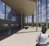
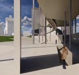
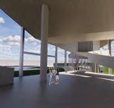
 Entrance Under AuditorimGallery
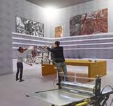
Gallery Looking at EntrancePrinting Studio
Entrance Under AuditorimGallery
Gallery Looking at EntrancePrinting Studio