
Alive
fabrication
Junyu Yang MArch Bio-integrated Design | UCL BArch Architecture | Tsinghua
Digital
of photosynthetic products
Junyu Yang
(+86) 188-1102-9079 | junyu.yang.21@ucl.ac.uk | jy-yang16@mails.tsinghua.edu.cn
EDUCATION
Fabrication, Bio-integrated Design | University College London Sep. 2021-Jul. 2023

Architectural Design | Tsinghua University Sep. 2016-Jul. 2021
AWARDS AND SCHOLARSHIPS
Tsinghua
Abstract
PUBLICATIONS
A Ferris Wheel Community Designed for Autistic Children [J]. Urban Design, 2020 (02): 100-105.
*First Author, Leader of the design team
WORKING EXPERIENCE
B.L.U.E. Architectural Studio. | Intern | Beijing July. 2021- Sep. 2021
People’s Architecture Office. | Intern | Beijing Feb. 2021- May. 2021
Tsinghua University Architectural Design Institute | Intern | Beijing May. 2020- Jul. 2020
This portfolio explored the application of digital fabrication in creating photosynthetic living products. Microalgae was applied to materials for its photosynthetic behavior helps absorb carbon dioxide and release oxygen in environment, which is beneficial considering climate change and global warming as background. The research started at microalgae species Chlamydomonas reinhardtii, then hydrogel materials were studied to embed microalgae into 3D printed objects. A canopy design made of hydrogel and algae was the first project. Afterwards, ceramic was added as scaffold material for its strength that suitable for construction, and hygroscopic property that provides moisture to the embedded microalgae. Therefore, a type of algae tiles was designed to promote growth of algae and plants on facade and roof of an architecture, which is the final project of this almanac.
2
Urban
Studies | Osaka University Sep. 2018-Feb. 2019
2020 China Scholarship Council Scholarship 2018 Tsinghua University Academic Excellence Award 2017
Alumni-Ni Tianzeng Education Scholarship
Project 1: Algae Canopy
1.1.1 Algae Chlamydomonas. reinhardtii and 3D bio-printing 5
1.1.2 Arduino controlled syringe pump for algae injection 6
1.1.3 Hydrogel channel created by partial cross-linking 7
1.2 Hydrogel geometry printed by WASP 3D printer 8
1.2.1 WASP 3D printed hydrogel grids 8
1.2.2 WASP 3D printed multilayered hydrogel grids 9
1.2.3 WASP 3D printed complex hydrogel geometry 10
1.3 Final design and fabrication model 12
1.3.1 Fibrous hydrogel model 12
1.3.2 Houdini vex coding for hydrogel fabrication 13
1.3.3 Fianl model on UCL Bartlett Bpro show 2022 15
2.1 Tool design and manufacture 17
2.2 Hydrogel lattice design prototype 18
2.3 Dual extruder design and manufacture 20
2.4 Robotic fabrication of hydrogel lattice prototype 1 22
2.5 Robotic fabrication of hydrogel lattice prototype 2 26

3.1Fabrication experiments 31
3.1.1 Robotic printing on scanned object test 31
3.1.2 3D printing of textured ceramic test 32
3.1.3 3D printing of twisted vase ceramic test 33
3.2.1 Textured clay panel design prototype 1 34
3.2.2 Textured clay panel design prototype 2 35
3.2.3 Long textured ceramic panel design 36
3.3 Environmental analysis of printed panels 40
3.3.1 Solar and curvature analysis of panel scan 40
3.3.2 Water flow simulation of panel scan 41
3.4 Bio-printing algae hydrogel on printed panles 42


3.4.1 Robotic fabrication set up 42
3.4.2 Bio printing of algae-hydrogel test 43
3.4.3 Bio-printing of ceramic panel 1 44
3.4.4 Bio-printing of ceramic panel 2 45
3.4.5 Bio-printing of long ceramic panel 3 parts 46
3.4.6 Algae tiles prototypes photography 48
3
Project 3: 3D printed Algae Tiles
Project 2: Robotic fabrication of hydrogel lattice
Table of Contents

2022- Sep. 2022
Project 1: Algae Canopy Feb.
1.1 Microalgae and material research


1.1.1 Algae Chlamydomonas. reinhardtii and 3D bio-printing


Chlamydomonas reinhardtii is a single-cell green alga, with two anterior flagella of equal length and eyespot to sense light. This species widely distributes on soil surface and fresh water worldwide, it is a model organism for numerous biological processes that well studied by many researchers. The two flagella enable Chlamydomonas to have many special behaviors, such as interaction with surface of habitat and phototaxis to light. The flagella of Chlamydomonas provides a light-switchable adhesiveness to the surface it grows, which help this species to adapt to light change in the environment and achieve high efficiency of photosynthesis(Kreis et al., 2017). This characteristic of adhesion can be very useful in algae-integrated design, as most algae is easy to peel off or be washed off from designed objects due to drought or rainfall. What’s more, as a model organism, there are many existed scientific research about Chlamydomonas and can be resourceful to combine these knowledges into design. Therefore, Chlamydomonas reinhardtii was chosen as the microalgae species for this project.

5 22/04/07 22/04/07 Day 3 22/04/09 22/04/09 Day 5 22/04/11 22/04/11 Day 9
Figure 1: Cultivation of algae Chlamydomonas reinhardtii
Figure 2: Movement of Chlamydomonas in hydrogel
Arduino Script:
#include <Stepper.h>
//Define number of steps per revolution const int stepsPerRevolution = 200;
//the number of steps in one revolution of your motor. If your motor gives the number of degrees per step, divide that number into 360 to get the number of steps (e.g. 360 / 3.6 gives 100 steps).
//int stepSpeed = 60;
String str = “”;
//Give the motor control pins names, all Digital pins:
#define pwmA 3
#define pwmB 11
#define brakeA 9
#define brakeB 8
#define dirA 12
#define dirB 13
//Initialize the steper library on the motor shield: Stepper myStepper = Stepper(stepsPerRevolution, dirA, dirB);
//Stepper(steps, pin1, pin2)
int counter = 0;
void setup() {
//Set the PWM and brake pins so that the direction pins can be used to control the motor:

pinMode(pwmA, OUTPUT);
pinMode(pwmB, OUTPUT);
pinMode(brakeA, OUTPUT);
pinMode(brakeB, OUTPUT); digitalWrite(pwmA, HIGH); digitalWrite(pwmB, HIGH);
digitalWrite(brakeA, LOW); digitalWrite(brakeB, LOW);
//Set the motor speed (RPMs): myStepper.setSpeed(10); //rotations per minute Serial.begin(9600);//a baud rate. }
void loop() {
//Step one revolution in one direction: // 200= 1 rotation
str = Serial.readString(); Serial.println(str); if(str.indexOf(“push”)>-1){
int split = str.indexOf(“ “); String substr = str.substring(split); 200*substr.toInt();
myStepper.step(200*substr.toInt()); } else if(str.indexOf(“pull”)>-1){
int split = str.indexOf(“ “); String substr = str.substring(split); 200*substr.toInt();
myStepper.step(-200*substr.toInt());
6
} }
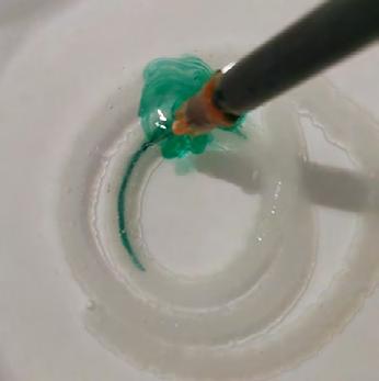
1.1.2 Arduino controlled syringe pump for algae injection
Figure 3: 3D printed syringe pump to extrude algae concentrate
Figure 4: Hydrogel strand injected with living algae concentrate
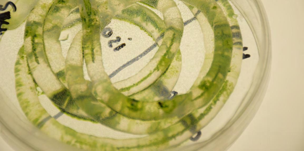
1.1.3 Hydrogel channel created by partial cross-linking


In general, algae immobilization means mixing algae slurry and hydrogel material together. Another way of immobilizing algae into hydrogel was explored here, by injecting algae slurry into partial crosslinked hydrogel strand. And internal channel was found in some material compositions after certain time of crosslinking. These channels may be formed by incomplete cross-linking of the strand, whose outside surface is cross-linked and become hard, while the inside remains viscous and soft, therefore liquid can dissipate inside.


Among all material samples tested, only hydrogel samples composed of sodium alginate and methylcellulose have internal channels after partial crosslinking. The experiments were conducted in the following steps. First extruding samples into 0.1M/L CaCl2 solution using 4mm nozzle syringe, and keep for 30 minutes; Then, put the crosslinked samples into distilled water for 2 hours to absorb water; In the end, using a 0.5mm needle to inject food color into the strands, and observe the liquid flow inside. For material samples proved to have internal channels, living algae slurry was injected inside with the same previous steps, to record the algae growth. The green channel formed by algae inside became obviously greener after 4 weeks. (Junyu thesis, 2022)

7
Water Sodium alginate Methylcellulose 50ml 1.5g 4.5g
Figure 5: Hydrogel channel formation process
1.2 Hydrogel geometry printed by WASP 3D printer

1.2.1 WASP 3D printed hydrogel grids


In previous research of bio-printing living algae, algae concentrates were mixed with hydrogel and printed together in 3D geometries. Considering the formation of internal channel in hydrogel after partial crosslinking, further experiments were conducted to test if the internal channel can remain in 3D printed geometries, which have irregular shapes of section compared with round section of strands. Based on previous experiments of material compositions, N1 composition was proved to have the optimal internal channel after certain crosslinking process, therefore composition N1 was selected for the following experiments.
The first experiment aimed to test the internal channels formation in printed 2D patterns with intersection points. First, using composition N1 as printing material, and print single layered 2D patterns by WASP using 4mm nozzle. Second, spray 0.1M/L CaCl2 solution to maintain the shape immediately after printing. Then, immerse patterns into 0.1M/L CaCl2 solution for 30 minutes, and then immerse into distilled water for 2 hours. In the end, for each pattern, inject 1ml of algae concentrate at one side of pattern, cover the injection part with foil, put into growth chamber and record images. (Junyu

8
Grid- 4 branches Hexagon- 3 branches Triangle- 6 branches
Figure 6: Wasp printing process. Image from Junyu. 2022
thesis, 2022)
Figure 7: Printed samples after crosslinking. Image from Junyu. 2022
1.2.2 WASP 3D printed multilayered hydrogel grids


After the experiments with single-layer hydrogel geometry, multiple layer geometries were tested as well. With similar protocol, first use N1 composition as printed material, print 8 layered grid geometry by WASP using 4mm nozzle, and spray 0.1M/L CaCL2 immediately after printing to maintain the shape. Then immerse 3 printed objects into 0.1M/L CaCL2 solution for 30 minutes, 60 minutes, 90 minutes individually. (Junyu thesis, 2022)
30min crosslinked- water absorbtion overnight
60min crosslinked- water absorbtion overnight
90min crosslinked- water absorbtion overnight
9
Toolpath- 8 layered grid
Figure 8: Multilayered hydrogel grids. Image from Junyu. 2022
Figure 9: Multilayered hydrogel grids after crosslinking. Image from Junyu. 2022
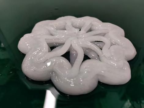
WASP 3D printed complex hydrogel geometry


10
1.2.3
Figure 10: Wasp printing process. Image from Junyu. 2022
Figure 11: Wasp printing process. Image from Junyu. 2022
Toolpath- complex hydrogel geometry


11
Figure 12: Printed hydrogel geometries with injected algae
Figure 13: Grasshopper scripts of printed complex geometry
1.3 Final design and fabrication model
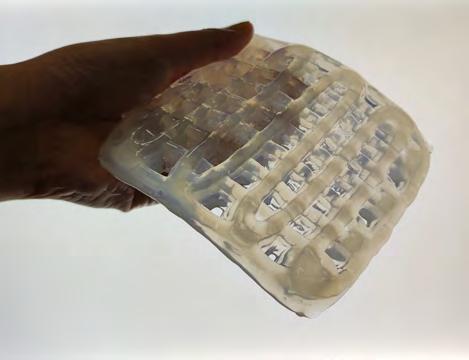
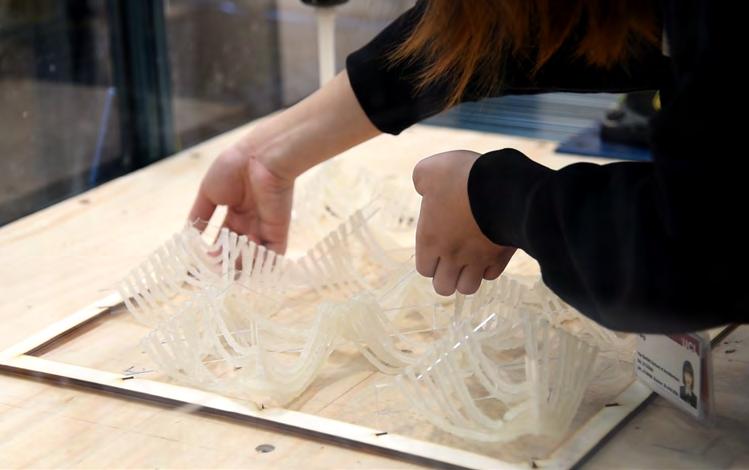
1.3.1 Fibrous hydrogel model

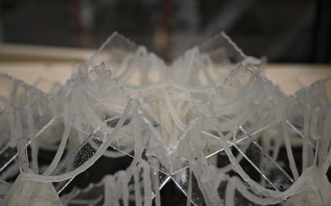
For the real hanging model of hydrogel, an acrylic scaffold and continuous hanging toolpath was designed, and the model was fabricated with Delta WASP 3D printer. To successfully print the desired hanging geometry, a dense hydrogel material was used to have better tensile strength, and the acrylic scaffold was calibrated accurately on the base of WASP printer to avoid any collision between nozzle and scaffold. During printing, the extrusion factor and flow rate were adjusted to get a good quality printing. Immediately after printing, calcium chloride solution was sprayed on the hydrogel strands to crosslink and solidify. After the hydrogel dried up, the model was removed from the scaffold and stuck together, as a final fabrication model for designed geometries, and was exhibited in the P-pro show.


12
Figure 14: Fabrication process with WASP printer and scaffold
Figure 15: Dried hydrogel fibrous model under sunshine


13
1.3.2
Houdini vex coding for hydrogel fabrication
13
Figure 16: Vex coding scripts

14
Figure 17: Model for exhibition on Bpro show 2022
1.3.3 Fianl model on UCL Bartlett Bpro show 2022


15
Project 2: Robotic fabrication of hydrogel lattice
Oct. 2022 - Dec. 2022

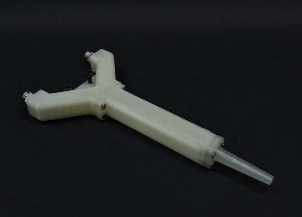
2.1 Tool design and manufacture

To print algae-laden hydrogel on objects with complex surface geometry and height change, a specific long nozzle needs to be made for robotic arm. The nozzle consists of three parts, a metal tube, a union with both sides outside thread, and a male stud coupling. All components were bought from schwer fitting with the help of Arthur Prior. There are 3 diameters of steel tubes for extrusion: 4mm, 6mm and 8mm. And the tubes can be cut by the bandsaw for the required length, for initial experiments, 15cm length tubes of each diameter were cut for the nozzles. For each size of tube, a compatible union and coupling were fitted on end of tube, and it can be mounted on the extruder of robotic arm.


To make the long nozzle, first, cut the metal tube to the desired diameter by using bandsaw in B-made, to get tube with certain length; second, sand the tube with sanding machine to have a smooth edge at the end of tube; Then, fix the matching coupling on the table, take out the rubber inside the coupling and put the tube through it. After putting the tube inside the coupling, turn the nut by using a span until is securely fastened, then loose the nut to see if the rubber has tightened together, if not, repeat the turning process until they stick to each other firmly. This is the whole process of making the long nozzle. I made 3 nozzles with 15cm length, and with 4mm, 6mm and 8mm inner diameter. They can all be installed to the robotic extruder well.


17
Figure 18: Calibrate long nozzle on robot
Figure 19: Long nozzles with 4mm, 6mm, 8mm diameters
Figure 20: Making process of long nozzles


18
3
Toolpath
Toolpath 2
Toolpath 1
2.2 Hydrogel lattice design prototype
Figure 21: Set up scaffold on WASP printer


19
Toolpath 1- Wet
Toolpath 1 - Dried
Toolpath 1 - Dried
Toolpath 2- Wet
Toolpath 2 - Dried
Toolpath 2 - Dried
Toolpath 3- Wet
Toolpath 3 - Dried
Toolpath 3 - Dried
2.3 Dual extruder design and manufacture
As for the possible multi-material printing, a dual extruder nozzle was also designed and assembled. The principle of dual extruder is using two cartridges filled with different materials, then mixing the two materials into a single nozzle when extruded by air pressure or motor. Therefore, the nozzle needs to have 3 parts, a joint tube to combine two strands of material into a single strand, a mixing tube with static mixer inside for two materials to mix homogeneously, and a nozzle with desired length and diameter for extrusion.


The dual extruder nozzle design is based on Guillem’s previous work. For the nozzle to be accurately assembled to the dual extruder, the distance between 2 openings of joint tube needs to be equal to the distance between two cartridges. And the thread size of joint tube openings needs to match the thread size of the cartridge output, so they can be fitted tightly to avoid material leaking. Also, it will be better if the 3 parts of nozzle can be assembled and disassembled, so it can be changed conveniently if different size of parts is needed. These are principles that I considered for designing the digital model of nozzle in Fusion 360.

The designed dual nozzle follows the above principles and has 3 parts separately. For joining the 3 parts together, inside threads were designed in each part for putting screws inside later. The joint tube has 8mm tube from the opening, then join into a single tube with 16mm diameter; The mixer tube has a typical static mixer inside; The nozzle has a diameter of 4mm at the end. After designing the digital model, the 3 parts were printed by utimaker 3D printer with transparent PLA material, with 100 per cent infill and without generating support. Then, screws were fitted into the thread holes of these parts to assemble them together.

20
Figure 22: Dual extruder design model
Figure 23: Dual extruder model with threads


21
Figure 24: Dual material 3D printed hydrogel lattice
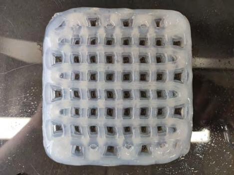
2.4 Robotic fabrication of hydrogel lattice prototype 1

Extrusion set up for KR6


A bigger scale scaffold was made as 40cm square size. The toolpaths designed also became more complex with more grids on the scaffold. This time, KUKA 6 industrial robotic arm was used for extruding hydrogel. Considering the height of scaffold, long nozzles with 18cm length were designed and printed as preparation. Due to thick nozzle edge and rough printing texture of nozzles made by me, a special long nozzle with 13.5cm length was bought online and used for the set up. The hydrogel material was filled in a cartridge, whose air pressure was controlled by a pneumatic solenoid valve as digital output. (Junyu. 2023)

22 135MM
Figure 25: Pneumatic Solenoid Valve
Figure 26: Extrusion set up
6MM 18MM 18MM 10MM 10MM 4MM
Figure 27: Long nozzle design
6MM 4MM
Scaffold design and toolpath exploration


23
Figure 28: Scaffold design
Figure 29: Robotic extrusion process simulation
Toolpath1
Toolpath2
Toolpath3
Toolpath1
Toolpath2
Toolpath3


24
Figure 30: Robotic printing process


25
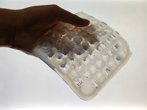
Figure 31: Hydrogel lattice prototype 1
An evolved version of scaffold was designed with bigger height change up to 13.5cm, which is an abstract representative of a more complex base geometry with greater height change on surface. Learn from previous experience of printing, the new scaffold has shorter distance between edges, and a more evenly distributed toolpath was designed to avoid breaking of hydrogel. Using the same set up, and same method of calibration, another hydrogel lattice was printed and recorded.


26
Figure 32: Robotic printing process simulation
Figure 34: Toolpath of prototype 2
2.5 Robotic fabrication of hydrogel lattice prototype 2
Figure 33: Extrusion set up


27
Figure 35: Robotic printing process


28
Figure 36: Hydrogel lattice prototype 2


29
Figure 37: Hydrogel lattice visualisation
Credit to Sameera Bommisetty
Project 3: Algae tiles
Feb. 2023 - Jul. 2023
Project 3: Algae Tiles

3.1Fabrication experiments

3.1.1 Robotic printing on scanned object test


To figure out the feasibility of printing on complex surface based on scanned digital model, a test was carried out with one carved foam board. After scanning the foam board, a simple curve toolpath was drawn on surface of the geometry and was converted to toolpath for robotic fabrication. It’s proved that the accuracy of scanned model is enough to print without collision on the real physical model.

31
Figure 38: Scanned model and toolpath Figure 39: Real model after printing
Figure 40: Operation process
Figure 41: Printing process
(Foam board credit to Dana Molzhigit)
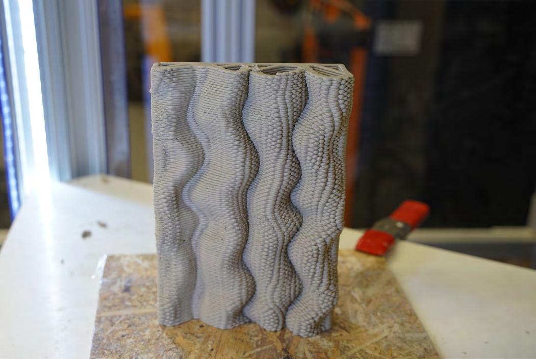
3.1.2 3D printing of textured ceramic test


32 32 32 Object diameter Object diameter Object diameter Pump number Pump number Pump number Object height Object height Object height 7cm 7cm 7cm NDP0800-03 NDP0800-03 NDP0800-03 10cm 10cm 10cm 1.5 1.5 1.5 Extrusion factor Extrusion factor Extrusion factor Nozzle diameter Nozzle diameter Nozzle diameter 4mm 4mm 4mm 1.2 1.2 1.2 Stepover factor Stepover factor Stepover factor Layer height Layer height Layer height 2mm 2mm 2mm 9190.79mm/min 9190.79mm/min 9190.79mm/min Extrusion speed Extrusion speed Extrusion speed Extrusion width Extrusion width Extrusion width 6mm 6mm 6mm 27.16s^ -1 27.16s^ -1 27.16s^ -1 Wall shear rate Wall shear rate Wall shear rate
Figure 45: Texture 1 - Smooth surface
Figure 46: Texture 2
Object diameter Object diameter Object diameter Pump number Pump number Pump number Object height Object height Object height 7cm 7cm 7cm NDP0800-03 NDP0800-03 NDP0800-03 10cm 10cm 10cm 1.5 1.5 1.5 Extrusion factor Extrusion factor Extrusion factor Nozzle diameter Nozzle diameter Nozzle diameter 4mm 4mm 4mm 1.2 1.2 1.2 Stepover factor Stepover factor Stepover factor Layer height Layer height Layer height 2mm 2mm 2mm 9190.79mm/min 9190.79mm/min 9190.79mm/min Extrusion speed Extrusion speed Extrusion speed Extrusion width Extrusion width Extrusion width 6mm 6mm 6mm 27.16s^ -1 27.16s^ -1 27.16s^ -1 Wall shear rate Wall shear rate Wall shear rate
- Uniform waves
Figure 42: Texture 4
- Vector attracted waves
Figure 43: Texture 5
- Points attracted waves
Figure 44: Texture 6
- Curve attracted waves
Figure 47: Texture 3
- Linear segments
3.1.3 3D printing of twisted vase ceramic test


33 33 33
Figure 48: Parametric vase grasshopper script
Object diameter Object diameter Pump number Pump number Object height Object height 7cm 7cm NDP0800-03 NDP0800-03 12cm 12cm 1.5 1.5 Extrusion factor Extrusion factor Nozzle diameter Nozzle diameter 4mm 4mm 1.2 1.2 Stepover factor Stepover factor Layer height Layer height 2mm 2mm 9190.79mm/min 9190.79mm/min Extrusion speed Extrusion speed Extrusion width Extrusion width 6mm 6mm 27.16s^ -1 27.16s^ -1 Wall shear rate Wall shear rate
Figure 49: Textured vase 1 to channel water flow
Figure 50: Textured vase 2 to channel water flow
3.2.1 Textured clay panel design prototype 1
After importing surface geometry into grasshopper, the waving toolpath was generated by using attractive lines - that drawn from red area of solar analysis result. Therefore, the roughness of the surface varies with sunlight distribution.


Surface 1
Digital surface Waving toolpath


34
June
June
June 12pm June 13pm June 14pm June 15pm June 16pm
Solar analysis June 9am
10am
11am
Figure 51: Panel 1 printing process
Figure 52: Printed panel 1


35
Solar analysis Digital surface Waving toolpath Surface 2 June 9am June 10am June 11am June 12pm June 13pm June 14pm June 15pm June 16pm
3.2.2 Textured clay panel design prototype 2
Figure 53: Panel 2 printing process
Printed panel
Figure 54:
2


36
Digital surface Waving toolpath part 1 part 2 part 3 June 9am June 10am June 11am June 12pm June 13pm June 14pm June 15pm June 16pm
toolpaths
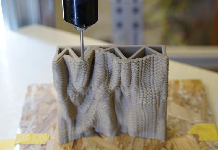
3.2.3
Long textured ceramic panel design
Figure 55: Printing
Figure 56: Grasshopper scripts of printing toolpath


37
Figure 57: Long panel 3 parts printing process
Long panel part 1
Long panel part 2
Long panel part 3


38
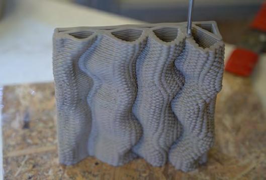
Figure 58: 3D printed ceramic panels

39
Figure 59: Fine texture of 3D printed ceramic panels
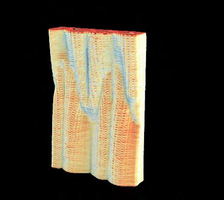
3.3 Environmental analysis of printed panels


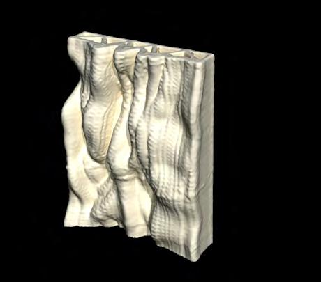


3.3.1


Solar and curvature analysis of panel scan


40


41
3.3.2
Water flow simulation of panel scan
3.4 Bio-printing algae hydrogel on printed panles


3.4.1 Robotic fabrication set up


42
Figure 60: Cartridge system for robotic extrusion
Figure 61: Cartridge filled with algae hydrogel Figure 62: Soft nozzle for printing
3.4.2 Bio printing of algae-hydrogel test

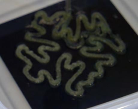


Before printing algae hydrogel on the ceramic, it’s important to know the printing performance of this material. Therefore, using a recipe tested in previous chapter (3g sodium alginate + 9g methylcellulose/ per 100ml water), liquid algae cultivation was added and mixed with hydrogel. Then the material was fed into cartridge of WASP printer and was printed into geometry as below. The shape of material maintains well below 4 layers, but when more layers were extruded the geometry started to collapse. Therefore, in further printing, the number of layers should be minimized. The immediate crosslinking process help the geometry to keep the original shape better, but still deformed as the hydrogel spread. The green colour of driedup hydrogel remained for over 1 month.


43
Figure 63: Bio printing process - details
Figure 64: Crosslinking process
Figure 65: Bio printing process
Figure 66: Dried-up algae hydrogel


44
3.4.3 Bio-printing of ceramic panel 1
Perspective view
Printing toolpath
Figure 67: Printing details
Figure 68: Printing process


45
3.4.4 Bio-printing of ceramic panel 2
Perspective view
Printing toolpath
Figure 70: Printing process
Figure 69: Printing details


46
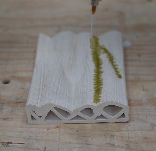
3.4.5 Bio-printing of long ceramic panel 3 parts
Part 1
Toolpath 1
Toolpath 2
Toolpath 3
Part 2
Part 3


47
Part 1 Part 1 Part 1
Figure 71: Robotic non-panar printing process


48
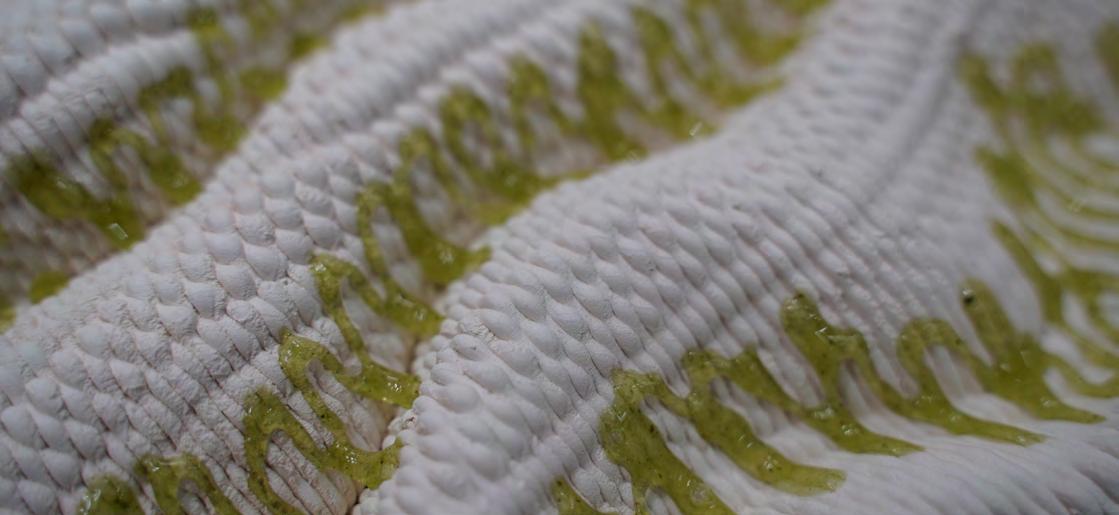
3.4.6 Algae tiles prototypes photography


49

